Domel AZ 150 User manual

AZ MOTOR
INSTRUCTIONS FOR BEARINGS REPLACEMENT
Edition 4 (June 2014)

AZ motor Edition 4
Instructions for bearings replacement 2
1. ABOUT INSTRUCTIONS FOR BEARINGS REPLACEMENT
In this document there are presented steps for safe bearings replacement in AZ motors. Every
step is described with text and pictures so that any kind of misunderstanding is minimized to a
low level.
Before any kind of motor disassembly you should read the instructions for bearings
replacement first.
During the bearings replacement you will need some standard and specially adjusted tools.
The list of tools is described in chapter 1.2.
Some parts of the motor must not be used again. The list of new motor parts is described in
chapter 1.3.
All pictures in this document are symbolic.
Domel d.o.o is not responsible for any kind of equipment damage, motor or EC controller
failure or any kind of personal injuries or material damage that were caused because of not
following the instructions for bearings replacement.
1.1 Explanation of safety signs and safety messages
Bellow there is presented the explanation of safety signs which are used in these instructions.
For your safety and safety of your equipment you should always follow safety signs.
DANGER indicates a hazardous situation with a high level of
risk.
WARNING indicates a hazardous situation with a medium
level of risk.
CAUTION indicates a hazardous situation with a low level of
risk.
NOTE.
Notes, additional information and instruction tips.

AZ motor Edition 4
Instructions for bearings replacement 3
1.2. List of tools and accessories for bearings replacement
In table 1 there are presented tools that you should use for safe bearings replacement.
Table 1. List of tools for bearings replacement
Tool
marking
Name of tool Picture of tool
(a) TORX T20 screwdriver
or tool
(b) TORX T30 screwdriver
or tool
(c) retaining ring pliers
(d) Heavy duty pliers
(e) INBUS (hexagonal)
tool 5 mm for M6
screw
(f) three M6 eye bolts (AZ
84) OR two M8 eye
bolts (AZ 108 and AZ
150) OR
two eye bolts with
thread M14x1,5 (AZ
220)
or or
(g) small flat screwdriver

AZ motor Edition 4
Instructions for bearings replacement 4
(h) pliers
(i) 2 or 3 handed puller
We recommend to use
the puller from
KUKKO manufacturer
(www.kukko.com) with
small pulling arms.
(j) inductive heater
(k) special tools for front
bearing installation
We recommend using
bearing fitting tool kit
TMFT 36 from SKF
manufacturer
(www.skf.com).
(l) centring tube
(picture 1)
(m) torque wrench

AZ motor Edition 4
Instructions for bearings replacement 5
(n) assembly grease
(o) adjusted press ring
(picture 2)
(p) sharp knife
(r) rubber hammer
(s) tool for fan wheel
installation
(t) Wrench 19 mm
Dimensions for centring tube are described on picture 1 and in table 2. Dimensions for
adjusted press ring are described on picture 2 and table 3.

AZ motor Edition 4
Instructions for bearings replacement 6
Picture 1. Tube (tube provide concentric between rotor (shaft) and the stator support)
Table 2. Centring tube dimensions
No.
Motor type A[mm] B[mm] C[mm] x/y [mm/ ˚] y [˚]
1 AZ 108 26,65 24,65 100 0.25 45
2 AZ 150 34,75 29,75 150 1 60
3 AZ 220 54,7 34,7 150 4 60
Dimension C can be longer if needed.

AZ motor Edition 4
Instructions for bearings replacement 7
Picture 2. Adjusted press ring dimensions
Table 3. Adjusted press ring dimensions
No.
Motor type d[mm] D[mm] E[mm]
1 AZ 84 6,5 16 34,5
2 AZ 108 4,5 18 39.5
3 AZ 150 6,5 25.5 51.5
4 AZ 220 6,5 30.5 61.5

AZ motor Edition 4
Instructions for bearings replacement 8
1.3. List of new motor parts
In table 4 there is presented list of new motor parts. Which bearing type must be used
according to motor size is described in table 5.
Table 4. List of new motor parts
2 pieces of new bearing according
to table 5.
1 piece of new wave spring washer
according to table 5
Grounding brush support with
brushes
Dimensions:
54x15x11,3 for 748.3.xxx motors
(motor size AZ 150)
64x15x11,6 for 749.3.xxx motors
(motor size AZ 220)
New larger press ring
For 748.3.xxx motors (motor size
AZ 150)
For 749.3.xxx motors (motor size
AZ 220)
Table 5: Bearing types and wave spring washer according to motor sizes
Motor
Code
Motor size
Bearings type Size of wave spring
washer
(d1 x d2 x s x h)
Shaft end Not shaft
end
C3E D EA3S
NSK
C3E D EA3S
NSK
746.3.392 AZ 84-50 6202 ZZ 6202 ZZ 28x34,5x0,6x3
747.3.192 AZ 108-30 6204 DDU 6203 DDU 33x39,1x0,5x2,9
747.3.194 AZ 108-30 6204 DDU 6203 DDU 33x39,1x0,5x2,9

AZ motor Edition 4
Instructions for bearings replacement 9
747.3.392 AZ 108-55 6204 DDU 6203 DDU 33x39,1x0,5x2,9
747.3.397 AZ 108-55 6204 DDU 6203 DDU 33x39,1x0,5x2,9
748.3.292 AZ 150-45 6205 ZZ 6205 ZZ 42x51x0,5x3,4
748.3.492 AZ 150-70 6205 ZZ 6205 ZZ 42x51x0,5x3,4
748.3.496 AZ 150-70 6205 ZZ 6205 ZZ 42x51x0,5x3,4
749.3.392 AZ 220-55 6206 ZZ 6206 ZZ 51x61x0,5x3,7
749.3.393 AZ 220-55 6206 ZZ 6206 ZZ 51x61x0,5x3,7
749.3.692 AZ 220-100 6206 ZZ 6206 ZZ 51x61x0,5x3,7
749.3.694 AZ 220-100 6206 ZZ 6206 ZZ 51x61x0,5x3,7
749.3.695 AZ 220-100 6206 ZZ 6206 ZZ 51x61x0,5x3,7
749.3.901 AZ 220-55-
100 6206 ZZ 6206 ZZ 51x61x0,5x3,7
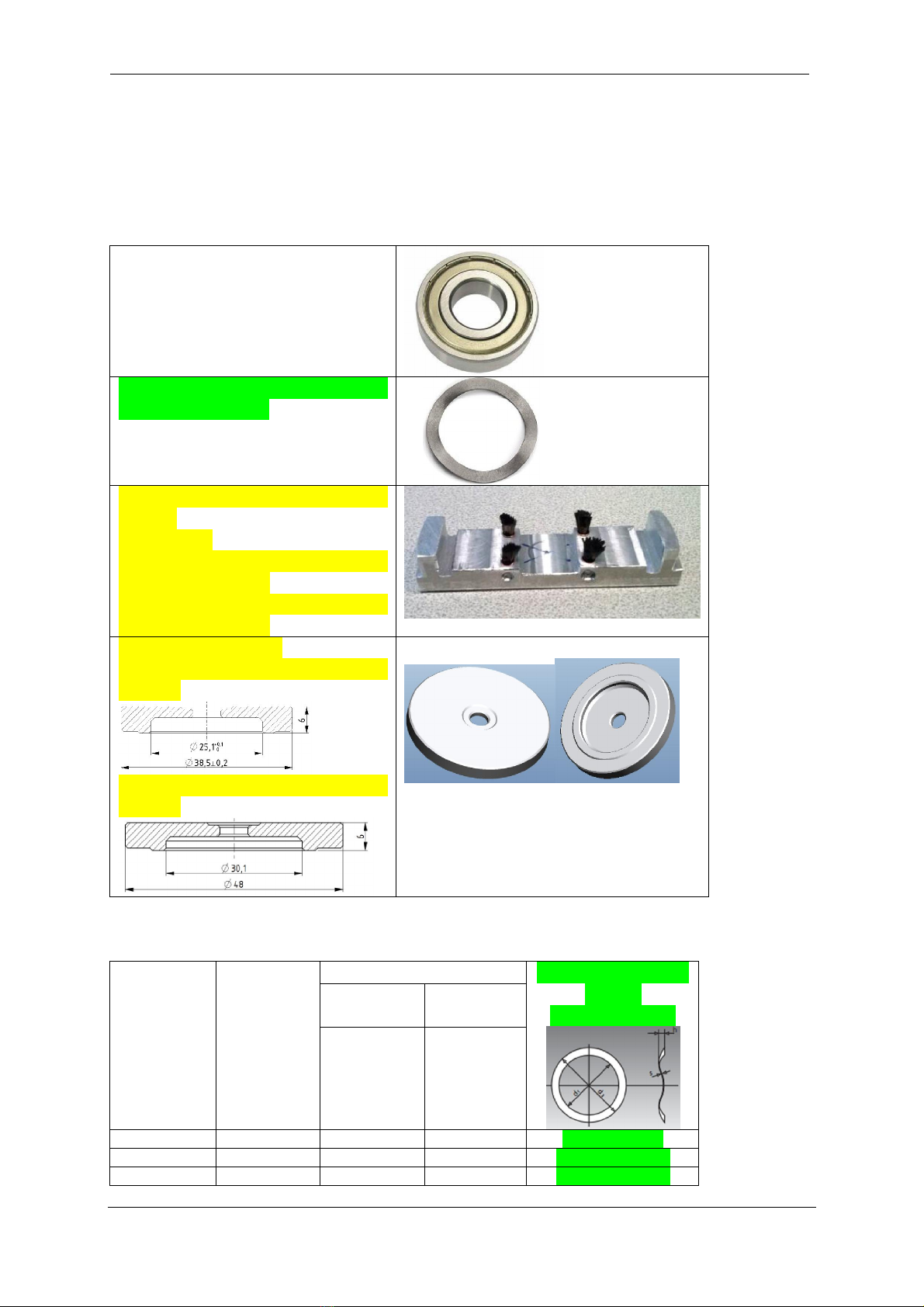
Sufficient bearings life time is guaranteed
just with bearings specified in table 5.
These bearings are filled with special
grease that ensures appropriate life time.
Using other bearing types can lead to
shorter motor life time and Domel cannot
guarantee for these bearings.
Explanation of bearing designation:
6205
ZZ
C3
E
D
EA3
S
NSK
Bearing producer
Grease quantity
S - standard (35% of free bearing space)
Type of special grease
Production location
Noise level mark
E – quiet bearing
Radial internal clearance
C3 - 6202, 6203 (11-25 m)
6204, 6205, 6206 (13-28 m)
Bearing sealing
ZZ – shields on both sides
DDU – contact rubber seals on both sides
Bearing geometry number
Other data important for new bearing selection:
Consider ambient temperatures expected for motor operation (Motors are designed for
long term operation at temperatures from -40°C to +52°C).
Max. long term bearing operating temperature can reach 80°C
Grease viscosity must prevent grease leakage from bearing

AZ motor Edition 4
Instructions for bearings replacement 10
2. ABOUT AZ MOTORS
2.1. Motor introduction
External rotor motor types AZ are electronically commutated motors with high efficiency at
all operating area and low level of noise. The high efficiency is reflected in low motor
heating. The motors can operate between -40 and +52°C ambient temperature.
AZ motors are designed in four lamination diameters of stator: 84 mm (AZ 84), 108 mm (AZ
108), 150 mm (AZ 150) and 220 mm (AZ 220). They are made in degree of protection IP54
(closed housing). The motors are equipped with connecting cables and can be easily
connected with motor controllers.
Electronically commutated motor must be always used together with a motor controller.
Motor cannot operate without controller. Motor must not be connected directly to
voltage supply.
2.2. Purpose of usage
AZ motors are designed as standard industrial motors. On the motor shaft it is possible to
mount different types of fans used for all kind of purposes. Beside fans drive they can be used
for drive of water pumps, air compressors and all kind of industrial machines, where precise
speed regulation is needed.

AZ motor Edition 4
Instructions for bearings replacement 11
2.3. Main motor parts:
2.3.1. Parts of motor AZ 84
Picture 3. Main motor parts – AZ 84

AZ motor Edition 4
Instructions for bearings replacement 12
Table 6. Main motor parts – motor AZ 84
Number
Component part
1
Stator support
2
Stator
3
Housing
4
O
–
ring (i
n the bearing seat of the Housin
g
–
pos. 3
)
5
Rotor (with magnets)
6
Shaft
7
Bearing, front
8
Bearing, rear
9
Wave spring washer
10
Distance ring
11
Bearing fixation washer
12
Screw
M6
13
Parallel Key
14
Stator support c
over
15
Screw
M6
16
Bonding screw
M6
17
S
crew
M4
18
Con
necting cable
19
Connector for motor connection
2
0
Connector insulation
2
1
Terminal box
2
2
Terminal box seal

AZ motor Edition 4
Instructions for bearings replacement 13
2.3.2. Parts of motors AZ 108, AZ 150, AZ 220

AZ motor Edition 4
Instructions for bearings replacement 14
Picture 4: Main motor parts – AZ 108, AZ 150, AZ 220

AZ motor Edition 4
Instructions for bearings replacement 15
Table 7. Main motor parts – AZ 108, AZ 150, AZ 220
Number
Component part
1
Stator support
2
Stator
3
Housing
4
Flange
5
Rotor (with magnets)
6
Shaft
7
Bearing, front
8
Bearing, rear
9
Wav
e spring washer
10
S
him washer
11
Retaining ring
12
Press ring
13
Screw
14
O
–
ring (on the Stator support
–
pos. 1 and on the Flange
–
pos. 4)
15
O
–
ring (in the bearing seat of the Flange
–
pos. 4)
16
Parallel Key
17
Cover
18
Screw
19
Bonding
screw
20
Washer
21
Ground screw
22
Connecting cable
23
Identification label
24
Eye Nut

AZ motor Edition 4
Instructions for bearings replacement 16
3. SAFETY INSTRUCTIONS AND WARNINGS
THE OPERATING AND INSTALLATION INSTRUCTIONS
MUST BE READ BEFORE THE INSTALLATION OF THE
MOTOR, IT'S USAGE AND IT'S MAINTENANCE!
INSTRUCTIONS FOR BEARINGS REPLACEMNET MUST BE
READ BEFORE ANY KIND OF MOTOR MAINTENANCE!
RISK OF ELECTRIC SHOCK.
ELECTRICAL CONNECTION HAS TO BE PERFORMED
ONLY BY QUALIFIED PERSON!
RISK OF ELECTRIC SHOCK.
ELECTRICAL CONNECTION IS ALLOWED TO BE
PERFORMED ONLY IF THE VOLTAGE SUPPLY IS
DISCONNECTED.
RISK OF ELECTRIC SHOCK.
MOTOR MUST NOT BE CONNECTED IF ELECTRICAL
CABLE IS DAMAGED!
RISK OF ELECTRIC SHOCK.
ANY KIND OF MAINTENANCE OF THE MOTOR IS
ALLOWED ONLY IF VOLTAGE SUPPLY IS DISCONNECTED
AND THE MOTOR SHAFT NOT ROTATED!
RISK OF INJURY.
BEFORE STARTING THE MOTOR FASTENING OF THE
MOTOR HAS TO BE CHECKED.
POTENTIAL FALL OF THE MOTOR.
MOTOR SHAFT MUST NOT BE USED FOR THE TRANSPORT
OF THE MOTOR.
POTENTIAL FALL OF THE MOTOR.
ELECTRICAL CABLE MUST NOT BE USED FOR
TRANSPORT OF THE MOTOR!
MOTOR CABLE DAMAGE IS POSSIBLE.

AZ motor Edition 4
Instructions for bearings replacement 17
4. SERVICING OF THE MOTOR FOR BEARINGS
REPLACEMENT
Replacement of the motor bearings is an example of service
intervention.
Any service intervention should be performed by a qualified
person.
Disturbing noise from fan motor!
Check by spinning the wheel by hand and listen for noise from the bearings.
Establish the replacement of bearings if noise from bearings is detected.
RISK OF ELECTRIC SHOCK.
Before service intervention, ensure that motor controller is
disconnected by the mains voltage and that motor does not rotate.
The fan, mounted on the motor shaft, could rotate due to influence
of the overpressure in the air channel or wind. The rotation of the
fan causes the rotation of the motor. In such case the motor
generates electrical voltage. And a touch of the non-insulated wires
of the connection cable can lead to serious injuries.
RISK OF INJURY BECAUSE OF FLYING OBJECTS.
During the service intervention protecting glasses and protective
gloves should be used.

AZ motor Edition 4
Instructions for bearings replacement 18
Step 1: Removing the fan frame with motor
Remove the fan frame with motor from AHU. Motor controller must be disconnected from
mains.
Step 2: Removing the wheel
Remove the inlets, fan wheel screw and wheel from motor shaft (Inter dismantle front
profile).

AZ motor Edition 4
Instructions for bearings replacement 19
Step 3: Disconnecting motor cable from motor controller
You will need a TORX T20 screwdriver (a) and a small flat screwdriver (g) for this step
Open the cover of motor controller and disconnect the motor cable from motor controller.
Step 4: Positioning the motor in vertical direction
RISK OF INJURY.
For larger motor sizes use lift and be careful not to injury yourself.
Be careful not to damage fan housing, motor or motor cables.
Place the fan housing with motor in vertical direction as shown on picture bellow.

AZ motor Edition 4
Instructions for bearings replacement 20
Step 5: Fixing the motor shaft
In this step you must fix motor shaft so that it cannot move axially.
Avoid forces in axial or radial direction that are pulling the shaft
out or pressing the shaft in. You can damage wave spring washer.
For fixing the shaft you can use e.g. a plastic tie as shown on
picture bellow.
Be careful not to damage the shaft.
Fix the motor shaft.
Step 6: Removing terminal box and disconnection of cable
You will need a TORX T20 screwdriver (a) and a small flat screwdriver (g) for this step.
Be careful not to damage motor wires, connector and connecting
cable.
Be careful not to damage terminal box seal.
MOTOR AZ 84
Unscrew four motor fixation bolts and remove motor from frame – PICTURE A.
Untighten cable gland nut and release the connecting cable (pos. 18).
Unscrew four M4 screws (pos. 17) and gently pull out the terminal box (pos. 21) with seal
(pos. 22). Use TORX T20 screwdriver (a). You will have to push the connecting cable into
cable gland to slide inside. When you get enough place to disconnect the cable, stop to pull.
Disconnect the connecting cable (pos. 18) from connector (pos. 19). Use a small flat
screwdriver (g) with pressing the pins of connector – PICTURE B.
Unscrew ground screw and screw for cable screen connection and remove connection cable
together with terminal box
This manual suits for next models
4
Table of contents