Dominator Select DSO-1 User manual

These instructions are intended for professional garage door
installers.All references are taken from inside looking out.
Select
Doc # 160407_00
Part # 87186
Released 12/11/19
Sectional Door Opener
Select
DSO-1

Dominator Select Instruction Manual2
Contents
1. Installation Safety Warnings! 3
2. Before you Begin 4
3. Tools Required 4
4. Kit Contents 5
5. Position 5
6. Fit the Opener 6
7. Bracket Position 6
7.1Wall Bracket Position: 6
7.2 Mounting the Wall Bracket: 6
7.3 Attach the Track to the Wall Bracket 6
8. Perforated Angle 7
9. Mounting Brackets and Arms 7
9.1 Mounting the Door Bracket: 7
9.2 Attaching the Arms 7
10. Optional Safety Beam Kit 8
11. Specifications 8
12. Setting Limits 9
12.1 Set the Limit Positions, adjust drive speed: 9
12.2 Clearing the Door Limit Positions 9
12.3 Re-proling the Door 9
13. Safety Testing 10
13.1 Test the Close Cycle 10
13.2 Testing the Open Cycle 10
13.3 Test the Manual Door Operation 10
14. Auto-Close 11
Installation Instructions
15. Coding a Transmitter 12
15.1 Storing the Transmitter Code 12
15.2 Installation of the Wall Mounted Transmitter 12
15.5 Remotely Coding Transmitters 12
15.3 Erasing All Transmitter Codes 12
15.4 Vacation Mode 12
16. Home Owner Safety Warnings! 13
17. Opener Safety & Security 14
17.1 Your Door CAN NOT be used when: 14
17.2 Your Door CAN be used when: 14
17.3 To Disengage the Opener: 14
17.4 To Re-Engage the Opener: 14
18. Operating your Opener 14
19. User Operating Controls 15
20. Troubleshooting 16
21. Maintenance 18
21.1 Door Maintenance 18
21.2 Battery Replacement 18
21.3 Battery Disposal 18
22. Appendix 19
A - Status Indication during Operating Mode. 19
B - Adjustment Mode Instructions 20
C - Adjusting Force Margins 20
D - Setting Limits via Transmitter 21
E - Setting the PET mode position 21
F - Setting up Tilt Door 22
23. Warranty 23
Home Owner Instructions
WARNING! IMPORTANT SAFETY INSTRUCTIONS
FOLLOW ALL INSTRUCTIONS SINCE INCORRECT INSTALLATION CAN LEAD TO SEVERE INJURY.
•before installing the drive, remove all unnecessary ropes or chains and disable any equipment, such as locks, not needed for
powered operation;
•before installing the drive, check that the door is in good mechanical condition, correctly balanced and opens and closes
properly;
•install the actuating member for the manual release at a height less than 1,8 m;
•install any xed control at a height of at least 1,5 m and within sight of the door but away from moving parts;
•permanently x the labels warning against entrapment in a prominent place or near any xed controls;
•permanently x the label concerning the manual release adjacent to its actuating member;
•after installation, ensure that the mechanism is properly adjusted and that the drive reverses when the door contacts a 40 mm
high object placed on the oor.
•necessary information for the safe handling of a drive weighing more than 20 kg.This information shall describe how to use the
handling means, such as hooks and ropes;
•the drive must not be used with a door incorporating a wicket door (unless the drive cannot be operated with the wicket door
open);
•after installation, ensure that parts of the door do not extend over public footpaths or roads.
•vertical doors and gates need an anti-drop feature or device;
•information if a hazardous part of the drive is intended to be installed at a height of at least 2.5 m above oor level or other
access level;
•except for horizontally moving pedestrian doors, ensure that entrapment due to the opening movement of the driven part is
avoided

3Dominator Select Instruction Manual
1. Installation Safety Warnings!
WARNING! • The door may operate unexpectedly, therefore do not allow anything to stay in the path
of the door.
• When operating the manual release while the door is open, the door may fall rapidly
due to weak or broken springs, or due to being improperly balanced.
• The drive must not be used with a door incorporating a wicket door, unless the drive
cannot be operated with the wicket door open.
• The drive is intended to be installed at least 2.5m above the oor.
• Do not disengage the opener to manual operation with children/persons or any objects
including motor vehicles within the doorway.
• If the door is closing and is unable to re-open when obstructed, discontinue use. Do not
use a door with faulty obstruction sensing
• When using auto close mode, a Photo Electric beam must be tted correctly and tested
for operation at regular intervals. Extreme caution is recommended when using auto
close mode. All safety rules must be followed.
ELECTROCUTION! • Place opener in protected area so that it does not get wet.
• Do not spray with water .
• Disconnect the power cord from mains power before making any repairs or removing
covers. Only experienced service personnel should remove covers from the opener.
• If the power supply cord is damaged, it must be replaced by an Automatic Technology
service agent or suitably qualied person.
• Connect the opener to a properly earthed general purpose 240V mains power outlet
installed by a qualied electrical contractor.
CAUTION:
Emergency Access • If garage has no pedestrian entrance door, an emergency access device should be
installed.This accessory allows manual operation of the garage door from outside in
case of power failure.
Muscular strain • Practice correct lifting techniques (carton weighs approx 5.7kgs)
• Practice correct liting techniques when required to lift the door as per installation instructions.
Fall from ladder • Ensure ladder is the correct type for job.
• Ensure ladder is on at rm ground that will take the weight without the legs sinking.
• Ensure user has 3 points of contact while on ladder.
Crush injury from
unsecured door
• Place a 2 metre exclusion zone around area under the door while it is unsecured.
• Follow the installation instructions
Garage Door • Examine the door installation, in particular, springs and mountings for signs of wear,damage
and imbalance.
• The garage door must be well balanced. Sticking or binding doors must be repaired by a
qualied garage door installer prior to installation of the opener.
• Remove or disengage all garage door locks and mechanisms prior to installation of the
opener.
Entanglement • Never plug in and operate opener prior to installation.
• Keep hands and loose clothing clear of door and guides at all times.
Entrapment under
operating door
• DO NOT operate the opener unless the garage door is in full view and free from objects
such as cars and children/people. Make sure that the door has nished moving before
entering or leaving the garage
• In order for the opener to sense an object obstructing the door way, some force must
be exerted on the object. As a result the object, door and/or person may suffer minor
damage or injury.
• Ensure the garage door is in good working order by undertaking regular servicing.
• Install the optional wall transmitter in a location where the garage door is visible, but out
of the reach of children at a height of at least 1.5m.
• Photo Electric beams must be installed if the closing force at the bottom edge of the door
exceeds 400N (40kg)
This automatic garage door opener is designed and tested to offer safe service provided it is installed and
operated in strict accordance with the following safety warnings.Failure to comply with the following instructions
may result in death, serious personal injury or property damage.

Dominator Select Instruction Manual4
3.Tools Required
2. Before you Begin
DIY
DO NOT DO IT YOURSELF:
If any of the above door requirements are not met,
DO NOT attempt to x yourself. Please contact a
garage door professional. (P) 0800 366 462
Screwdrivers
Adjustable End Wrench
Sockets and Wrench
Pencil
Drill
2 x Screws
(M6 x 20mm)
Stepladder
Perforated Angle
Metal pieces
(32 x 32 x 1.5mm) x 1200mm length
4 x Screws
(M8 x 20mm)
4 x Bolts and Nuts
(M8)
Drill Bits
Pliers
Hack saw
Tape Measure
Level
2.2 Test the following before commencing installation:
a. The door MUST BE in good operating condition.
b. Manually move the door up and down, the door should move freely
without binding or sticking. When the door is fully closed it should raise
itself by 10cm off the oor. Retension door if necessary.
c. The maximum force required to move the door should not exceed 20kg.
d. Lift the door to about halfway. When released, the door should stay in
place.
2.1 Examine the conditions in the garage:
a. Look at the ceiling:
i. Is it plastered? The opener is mounted to a perforated angle which MUST be securely fastened to a structural
support.You will need to locate the structural beams in the ceiling which are generally 400mm apart.
ii. does it have exposed beams? The opener is mounted to a perforated angle which must be securely fastened
to a structural support like the exposed beams. You may need to install a 40mm thick board (not supplied)
between structural supports.
b. Look at the wall above the garage door.
i. Is it brick? The wall bracket MUST be securely fastened to the wall with suitable screws and ensure it does not
move.
ii. Is it timber? The wall bracket MUST be securely fastened to a structural
support.You may need to install a 40mm thick board (not supplied)
between structural supports to fasten the wall bracket to.

5Dominator Select Instruction Manual
4. Kit Contents
4
5
6
7
8
9
10
11
12
13
14
16
15
2
3
1
1. 1 x SDO drive unit
2. 1 x Wall mount transmitter
3. 2 x Transmitters
4. 1 x Bent arm door attachment
5. 1 x Straight arm door attachment
6. 1 x Wall bracket TS01
7. 1 x Door bracket Locator
8. 1 x Door bracket
9. 3 x Pin Snap SSP 8 ZNU 31080
10. 2 x Hex Head screw M8x25
11. 1 x Pin 0890
12. 2 x Clevis Pin 0829
13. 2 x Hex Serration ange nut M8
14. 4 x Hex ange screw ‘S’ M4 x 10
PLUS
15. 2 x Track Bracket
16. 1 x Pre-Assembled
track
5. Position
The Opener:
a. MUST BE installed in a dry position, protected from weather.
b. REQUIRES properly earthed 3 pin single phase power on the ceiling within an arms length of the opener.
c. Requires a MINIMUM HEADROOM of 57mm between the highest point of the door’s travel and the ceiling.
d. Use the diagram below as a reference when completing the installation.
10.00°
min
MINIMUM HEAD
ROOM FOR STEEL
RAIL 57mm
DOORS HIGHEST
POINT
210mm
3198mm*
3330mm
157mm
295mm
Rail no Extension Kit 3198mm
Rail + 1 Extension Kit 3988mm
Rail + 2 Extension Kits 4778mm
* Rail refers to 3160 rail
15
1
16
5
4
6
7
12
8
14
11 9
13
10
Perforated
Angle
129
9

Dominator Select Instruction Manual6
6. Fit the Opener
6.1Secure C-Rail to Opener:
a. Remove the Opener from the box, taking care of antenna (if tted).
b. Locate and insert the shaft of drive unit 1into the C-Rail’s sprocket.
c. Fix the two track brackets 15 with four (4) M4 x 8 screws 14 supplied in accessory pack.
d. Place drive unit back in packing box for protection.
Locate shaft into
the sprocket
16
1
14 WARNING!
DO NOT use tek screws
to afx rail. Only use
the screws provided,
and x these into the
threaded holes in the
chassis.
7. Bracket Position
7.1Wall Bracket Position:
a. Determine the centre of the door and mark this point with a line on the
wall above.
b. Raise the door and nd the highest point of travel of the rst (top) door
panel.
60mm
Level
WARNING! The Opener must be securely fastened to structural
supports, otherwise opener failure may ensue causing serious
personal injury and / or property damage.
DO NOT DO IT YOURSELF: If sufcient structural support can
not be found, contact a door profressional for installation.
DIY
c. Using step ladder and a level, transfer this height to the wall above the
door and mark a line 60mm above it, across the centre line.
7.2 Mounting the Wall Bracket:
a. Draw two lines extending 21.5mm from each side of the centre point.
b. Centre the wall bracket 6over the intersection of these two lines.
Mark centres for at least two holes and ensure it is into a solid mounting
point.
c. Drill holes in the wall with an appropriate bit.
d. Secure to the wall using:
i. IF CONCRETE OR BRICK:
8mm (5/6”) loxins/dynabolts.
ii. IF TIMBER:
wood screw #20 or similar (min. 50mm).
7.3 Attach the Track to the Wall Bracket
a. Leave the drive unit in its packing box on the oor for protection and
lift the other end of the C-Rail.
b. Attach the pre-assembled track 16 to the wall bracket 6with the
90mm long pin 11 and secure with the supplied pin snap 9.
16
11
9
6
6
15
Keep the Tracklock manual on hand as after setting limits in
Section 12, refer to the tracklock manual to tension the track
and set the tracklock.
tip

7Dominator Select Instruction Manual
8. Perforated Angle
8.1 Attach Perforated Angle or equivalent
a. Measure across the ceiling from the centre point 3177mm (+/- 150mm) to nd a supporting beam.
b. Create a perforated angle which best suits your site. Use a hack saw to cut the L shape metal strips. Secure the
perforated angle to a supporting beam using diagrams shown below.
c. Raise the drive unit to the ceiling mounted perforated angle and secure with M8x20mm screws and nuts
(not supplied). Strips should not extend more than 18mm below centre of drive unit mounting holes.
d. To prevent moisture on the C-rail running into the powerhead it is recommended a strip of silicon sealant is placed
across the top of the C-rail just before the opener.
Ceiling Beams that run towards the door requires:
1 x perforated L shape metal strip and
2 x shorter perforate L shape metal drop down strips..
Ceiling Beams that run parallel to the door requires:
2 x perforated L shape metal strips and
2 x shorter perforate L shape metal drop down strips..
(Not supplied)
9. Mounting Brackets and Arms
9.1 Mounting the Door Bracket:
a. The door bracket locator 7is placed over the door
bracket 8, on the door’s centre line one-third down the
top panel and mounted using M6 or equivalent screws
(not supplied),
b. STEEL DOORS ONLY: Bracket can be welded in place.
NOTE: If in doubt about the door’s strength, reinforcement
may be added to the door’s frame where necessary. Door
damage may occur if the bracket is installed on a panel
with insufcient strength. The opener’s warranty does not
cover damage caused to the door and/or door panels.
9.2 Attaching the Arms
a. Assemble the bent arm 4(connecting to the door) to the
right side of the straight arm 5with bolts 10 and nuts 13
supplied in the accessory pack. Connect the straight arm
8
7
7
12
9
4
13
6
10
9
12
8
5
5to the shuttle with a clevis pin 12 and a pin snap 9.Always use both bent and straight arms.
b. Connect the assembled arm to the bracket with clevis pin 12 and pin snap 9.
The angle “A” must be more than 10°.
A

Dominator Select Instruction Manual8
10. Optional Safety Beam Kit
10.1 Safety Beams
The Safety Beam Kit provides additional safety by preventing the door closing
when the beam is blocked by a car, child etc. When the Safety Beam Kit is
installed the Auto-close feature can be enabled if required.
a. To install the Safety Beam Kit, refer to the Safety Beam instruction supplied
with the kit.
b. After the beams are installed the beam alignment feature of the opener
can be used.
c. Turn power on to the opener.
d. Align the safety beams using the main light as a guide:
i. bright = aligned
ii. dull = not aligned or blocked
When the beam is aligned or if no beam is tted,continue with Setting Limits.
11. Specications
Technical Specications Select
DSO-1
Rated voltage range: 230V - 240Va.c.
Rated frequency: 50Hz / 60Hz
Rated power input: 165W
Door opening:
Maximum Door Area:
Maximum Door Weight:
Door must be well balanced and able to be operated by
hand, as per warranty conditions and AS/NZS 4505:2012
15m2
140kg*
Minimum headroom 57mm
Rated Operating Time 4 mins
Rated Temp +5oC to +40oC
Short Term Peak force: 700N
Door travel speed (mm/sec) 140mm
Rated load 400N
Nominal force 200N (20kg)
Receiver type Multi-frequency UHF FM
Receiver code storage capacity 64 X 4-button Transmitters
Transmitter battery CR2032 (3 Volts)
Courtesy light LED (Light Emitting Diodes)
Network connectivity Network ready
(requires optional smart phone control kit)
* Gross door weight, including all ttings
Note: During the open and close cycles, intermittent operations may occur in areas which experience very strong
winds.The strong wind puts extra pressure on the door and tracks which may in turn intermittently trigger the safety
obstruction detection system.

9Dominator Select Instruction Manual
12. Setting Limits
12.1 Set the Limit Positions and adjust drive speed:
When setting the Close limit, ensure the position is when the door
makes rst contact with the ground. Alternatively for the Open limit
the position should be at the height of the garage opening.
NOTE: The drive speed is set to the fastest setting by default. This
may not be suitable for larger doors or for single piece doors. For tilt
doors (J-Type only), please refer to Appendix F for initial setup.
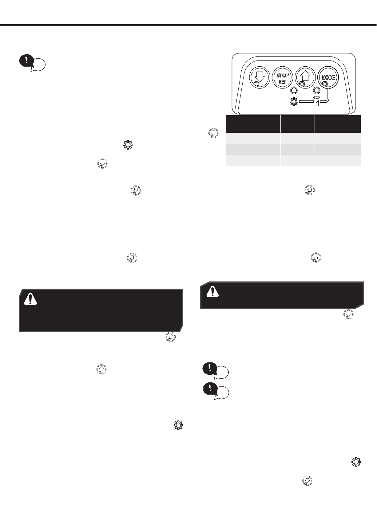
a. Switch power on and the BLUE LED on the CLOSE button
will start to ash and the GEAR LED is lit to indicate that the
opener is ready to set the Close travel limit.
b. Press either the CLOSE or OPEN button to move the door to
the halfway point.
WARNING! In setting the close limit position,
do not force the door into the oor with
excessive force, as this can interfere with
the ease of operation of the manual release
mechanism.
Door Opener
Speed Mode
STATUS MAIN LIGHT
Fast (Default) On 3 Flash
Medium On 2 Flashes
Slow On 1 Flashes
WARNING! The door will automatically close,
open and close again after the next step.
Ensure that nothing is in the door’s path.
NOTE: If unhappy with the speed or travel limit setting,
restart this procedure by resetting the door limit positions
as per below rst.
12.2 Clearing the Door Limit Positions
Limit positions can be deleted by:
a. Press the MODE button repetitively until the GEAR
LED is lit.
b. Press and hold the MODE button for 10 secs, let the
MODE button go when the main light stops ashing.
c. The close LED will ash continuously to indicate limits
have been cleared.
NOTE: If no action is taken within 30 seconds,the opener
will return to normal operating mode and restore the
original settings.
d. Follow from CLOSE limit: above to set new limit
positions, remembering to reset the tracklock.
CLOSE limit:
i. Press and hold the CLOSE button to start closing
the door, taking note of the speed the door moves.
ii. If the close speed is not suitable, to make a change,
press and hold the CLOSE button and by pressing
the STOP / SET button on the opener it will cycle
through all three speed modes as shown in table.
iii. Once at the desired speed, release the CLOSE
button.
iv. To set the close limit, inch the door by making single
presses of the CLOSE button to the desired
position. We recommend the CLOSE limit position
being the rst point of contact of the rubber strip
(at the bottom of the door) with the ground.
v. If the door overshoots, press the OPEN button to
move the door in the OPEN direction.
vi. When the door is at the desired CLOSE position,press
the STOP / SET button on the opener, the GREEN LED
on the OPEN button will now ash.
OPEN limit:
i. Press and hold the OPEN button to start opening
the door, taking note of the speed the door moves.
ii. If the open speed is not suitable, to make a change,
press and hold the OPEN button and by pressing
the STOP / SET button on the opener it will cycle
through all three speed modes as shown in table.
iii. Once at the desired speed, release the OPEN button.
iv. Continue inching the door to the desired position.
v. To set the open limit, inch the door by making
single presses of the OPEN button to the desired
position. We recommend the OPEN limit position
being the height of the garage opening.
vi. If the door overshoots,press the CLOSE button to
move the door in the CLOSE direction.
vii.When the door is at the desired OPEN position,press
the STOP / SET buttonThe door will now automatically
close and open to calculate the safety obstruction
settings.
12.3 Re-proling the Door
Re-proling is a simplied way of re-learning the travel
characteristic of a previously setup Limit Switch travel
installation. Re-proling can be used when the travel
characteristics of the door change due to mechanical
adjustments etc.To initiate a re-prole:
a. Limits must be set.
b. Press the MODE button repetitively until the GEAR
LED is lit.
c. Press and hold the CLOSE button for two seconds,
the door will open and close by itself to record prole.
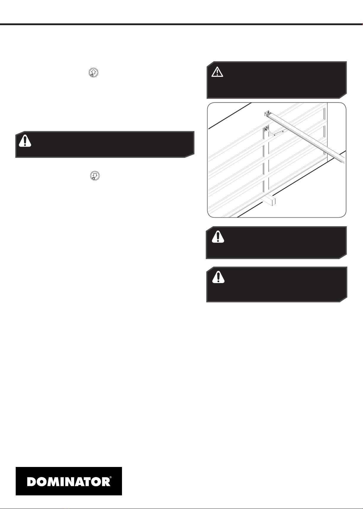
Once limits are set, refer to the tracklock
manual to set the tracklock and check
the tension of the track.
tip
If a tracklock is being installed with the opener, make
sure the tracklock plate is not secured in position until
limits are set. Refer to tracklock manual.
tip
Refer to Appendix B & C for adjustments
to margins.
tip

Dominator Select Instruction Manual10
13. Safety Testing
13.1 Test the Close Cycle
a. Press the OPEN button or transmitter button to open the
door (If the door starts closing, press the transmitter button to
stop the door, then press transmitter again to open).
b. Place a piece of timber approximately 40mm high on the
oor directly under the door.
c. Press the transmitter button to close door.
d. The door should strike the object and re-open.
e. Remove the timber .
13.2 Testing the Open Cycle
a. Press the CLOSE button or transmitter button to close the
door.
b. Press the transmitter button again to open the door.
c. When the door reaches approximately half way, rmly grab
the door’s bottom rail - the door should stop.
If the door does not reverse readily when closing, or stop when
opening, put the door into manual by pulling down on the
manual release string to diesengage the motor and contact
13 62 63 for support.
13.3 Test the Manual Door Operation
Periodically disengage the opener and manually operate the
door. The door must be smooth to operate by hand. The force
required on the bottom rail should not exceed 20kg.
CAUTION: Take care when completing a
safety test. Failure to follow this warning
can result in serious personal injury
and/or property damage.
WARNING! If the door is closing and is unable to
re-open when obstructed, discontinue use Do not
use a door with faulty obstruction sensing.
Wood 40mm high
WARNING! If the door fails these tests,
put the opener into manual mode,
only operate the door by hand and
call for service.
WARNING! Safety beams must be
installed if the closing force at the
bottom edge of the door exceeds
400N (40kg).

11Dominator Select Instruction Manual
14.Auto-Close
WARNING! It is compulsory to have
Safety Beams installed when using
Auto-Close mode.
Auto-Close mode is a function that automatically closes the
door after a pre-set time. Safety beams must be installed in
order to run the Auto-Close function. There are two types of
Auto-Close available:
i. Standard auto-close - the door will Auto-Close after
a programmed time. In this mode the timer starts to
countdown as soon as the door is fully open.This function
is useful in case the safety beam does not get triggered.
ii. Safety Beam triggered auto-close - the door will auto-
close after a programmed time. In this mode the timer
starts counting down only when the safety beam is
triggered. ie car leaving the garage.
To enable the Auto-Close function:
a. Press the MODE button repetitively until the GEAR LED
starts ashing.
b. Press the OPEN button until the GEAR LED ashes:
i. two (2) times to get to PE auto-close or
ii. three (3) times to get to standard auto-close.
c. Press STOP / SET button to enter parameter.
d. The default setting forAuto-Close is OFF.Press the OPEN button
to move through options and the light’s brightness will
change accordingly.
e. Press STOP / SET button to save the parameter’s new value or
press MODE to leave the value unchanged.
Parameter Value options = Indicated by brightness of
main light (DEFAULT parameter underlined)
Name Flashes 123456
PE AUTO-CLOSE 2OFF 15sec 30sec 60sec 90sec -
AUTO-CLOSE 3OFF 15sec 30sec 60sec 90sec 120sec

Dominator Select Instruction Manual12
15. Coding a Transmitter
15.1 Storing the Transmitter Code
The opener can only operated from remote control
transmitters that have been programmed into
its memory. Up to 8 codes can be stored in the
memory.
a. Press the MODE button repetitively until the
TRANSMIT LED is lit.
b. Press and HOLD the button/s indicated in the
table to set the required transmitter function.The
Main light will start to ash rapidly.
c. Press one of the four (4) buttons on the transmitter
until the main light starts to ash rapidly, then
release transmitter button.
d. Press the remote control button again until the
main light stops ashing rapidly.
e. Release both buttons. Press the MODE button to
exit. The transmitter button is now coded, press
to test.
NOTE: Refer to the Light indicator table for the
details of the transmitter status.
BUTTON
TRANSMITTER
FUNCTION
Open / Stop / Close HOLD
PET (Pedestrian) Mode HOLD
Open HOLD
Light HOLD HOLD
Vacation Mode HOLD HOLD
* The button coded for open only function can close the door if you
hold the button for 4 seconds, when the door is fully open..
MAIN LIGHT TRANSMITTER STATUS
ON Button added
OFF Button removed
2 FLASHES, then OFF Remote control deleted
4 FLASHES, then OFF Memory full
15.2 Installation of the Wall Mounted
Transmitter
a. Store the transmitter code as per instructions
above.Test the transmitter button.
b. Mount the transmitter in a convenient location,
yet out of reach of children and at least 1.5m off
the ground.
c. Make sure the door is visible from this location.
15.5 Remotely Coding Transmitters
Using this method transmitters can be coded without
access to the opener’s control panel as long as a
pre-coded transmitter is available.
a. Take any pre-coded transmitter. Press the button for the
function to be duplicated and release.
b. Using a small needle / pen, press and hold rmly for two
seconds the middle button, through the Coding Hole.
c. Within ten (10) seconds take the additional transmitter
you wish to code. Hold the new transmitter’s button for
two seconds, pause for two seconds, hold again for two
seconds and then release.
d. Wait for ten (10) seconds and then press the new
transmitter’s button to test.
15.3 Erasing All Transmitter Codes
a. Press the MODE button repetitively until the TRANSMIT
LED is lit.
b. Press and hold the MODE button for 10 secs,let the MODE
button go when the main light stops ashing.
c. Follow steps a - e in Storing the Transmitter Code to code
new transmitters.
15.4 Vacation Mode
a. To turn on Vacation mode and lock out all remotes, press
the button on the remote programmed with Vacation
Mode.
b. To turn off Vacation Mode, press the transmitter button
programmed to vacation mode to turn off.

13Dominator Select Instruction Manual
16. Home Owner Safety Warnings!
WARNING! IMPORTANT SAFETY INSTRUCTIONS
IT IS IMPORTANT FOR THE SAFETY OF PERSONS TO FOLLOW ALL INSTRUCTIONS.
SAVE THESE INSTRUCTIONS
This automatic garage door opener is designed and tested to offer safe service provided it is installed and
operated in strict accordance with the following safety warnings.Failure to comply with the following instructions
may result in death, serious personal injury or property damage.
WARNING! • Automatic Door - the door may operate unexpectedly, therefore do not allow anything
to stay in the path of the door.
• Details on how to use manual release. When operating the manual release while the
door is open, the door may fall rapidly due to weak or broken springs, or due to being
improperly balanced.
• DO NOT disengage the opener to manual operation with children/persons or any
objects including motor vehicles within the doorway.
• If the door is closing and does not re-open when obstructed, discontinue use. DO NOT
use a door with faulty obstruction sensing.
• Frequently examine the installation,in particular check cables, springs and mountings
for signs of wear, damage or imbalance. DO NOT use if repair or adjustment is needed
since fault in the installation or an incorrectly balanced door may cause injury..
ELECTROCUTION! • Place opener in protected area so that it does not get wet.
• DO NOT spray with water .
• DO NOT open the protective covers.
• DO NOT operate opener if cable is damaged. It must be replaced by the manufacturer,
its service agent or similarly qualied person in order to avoid a hazard.
• Disconnect the supply(s) when cleaning or other maintenance is being carried out..
DO NOT DO IT
YOURSELF
• Keep the garage door balanced. Sticking or binding doors must be repaired. Garage
doors, door springs, brackets and their hardware are under extreme tension and can
cause serious personal injury. DO NOT attempt any garage door adjustment. DO NOT
use if repair or adjustment is needed. Call for a professional garage door service.
CAUTION:
Emergency access • If your garage has no pedestrian entrance door,an emergency access device should
be installed.This accessory allows manual operation of the garage door from outside
in case of power failure.
Entrapment under
operating door
• Watch the moving door and keep people away until the door is completely opened
or closed. DO NOT operate door when persons are near the door.
• DO NOT allow children to play with door controls or transmitters. Keep remote controls
away form children.
• The appliance is not to be used by persons (including children) with reduced physical,
sensory or mental capabilities, or lack of experience and knowledge, unless they have
been given supervision or instruction.
• Children being supervised not to play with the appliance.
• Regularly conduct Open and Close cycle testing.
• Each month check that the drive reverses when the door contacts a 40mm high object
placed on the oor. Adjust if necessary and recheck since an incorrect adjustment may
present a hazard.
• Ensure the garage door is in good working order by undertaking regular servicing.
• Wall transmitters should be installed in a location where the garage door is visible, but
out of the reach of children at a height of at least 1.5m.
• Install Safety Beams (recommended).
Fall from Ladder • Ensure ladder is the correct type for the job.
• Ensure ladder is on at ground.
• Ensure user has 3 points of contact while on ladder.
Entanglement in or
laceration from
moving door
• Keep hands and loose clothing clear of door and guides at all times.
• Keep hands clear of moving door as sharp edges can cause cuts or lacerations.
DIY

Dominator Select Instruction Manual14
17. Opener Safety & Security
17.1 Your Door CAN NOT be used by the opener when:
a. There is an external locking device installed.
b. There is a power failure.
17.2 Your Door CAN be used when:
a. There is an emergency, by disengaging the opener.
b. There is a power failure, by disengaging the opener.
17.3 To Disengage the Opener:
a. It is recommended to do so with the door in the closed position.
b. Pull the manual release cord away from the door, until you hear
a click.
c. Move the door manually.
17.4 To Re-Engage the Opener:
a. Check the door has not been locked by a locking device.
b. Pull the manual release cord away from the door, until you hear
a click.
c. The door will now operate from the opener.
CAUTION: When the opener is manually
disengaged, the door is no longer locked. To lock
the door manually, re-engage the opener after the
door is closed.
18. Operating your Opener
18.1 To Operate the opener:
a. Press the programmed transmitter button until your
door begins to move (usually 2 seconds). Make
sure you can see the door when you use the
transmitter.
b. If you are in a vehicle you should aim the
transmitter through your windscreen as shown.
c. Check that the door is fully open or closed before
you drive in or away.
d. If you press the transmitter whilst the door is
moving the door will stop. The next press of the
transmitter will move the door in the opposite
direction.
WARNING! When operating the
manual release (while the door is
open) the door may fall rapidly due
to weak or broken springs, or due to
being improperly balanced.
Do not disengage the opener to
manual operation with children/
persons or any objects including
motor vehicles within the doorway.
DOOR
TO DISENGAGE
PULL HANDLE
AWAY FROM DOOR
AND RELEASE
TO RE-ENGAGE
PULL HANDLE
AWAY FROM DOOR
AND RELEASE
DISENGAGED SHUTTLE
ENGAGED SHUTTLE
IN THE EVENT THE
DOOR BECOMES
OBSTRUCTED
DETACH DOOR
FROM OPENER
AS FOLLOWS:
CAUTION: Do not use the string handle as a
mechanism to open the door. Failure to comply
may cause serious injury.
WARNING! Tracklock is NOT active
when opener is disengaged from the
track.

15Dominator Select Instruction Manual
19. User Operating Controls
05 06 07
01
02
03 04
Button Function
1. DOWN ARROW (Blue) Closes the door
2. DOWN ARROW LED (Blue) Illuminates when the door is closed and ashes when the door is obstructed on close or
stopped.
3. STOP (Red) Stops the door
4. UP ARROW (Green) Opens the door
5. UP ARROW LED (Green) Illuminates when the door is open and ashes when the door is open with the auto-close
timer running, obstructed on opening or stopped.
6. MODE (Yellow) Enables Load Diagnostics Mode
7. MODE STATUS LED (Yellow) Illuminates when in Diagnostics Mode
8. REMOTE CONTROL
STATUS LED (Red)
Flashes on remote lockout and ickers on remote control activity
9.ADJUSTMENT LED (Yellow) Flashes a certain number of times depending on the parameter being changed.
0809

Dominator Select Instruction Manual16
20.Troubleshooting
Symptom Possible cause Remedy
The opener does
not work from the
transmitter
Garage door in poor condition e.g.
springs may be broken
The opener does not have power
The battery in the transmitter is at
The opener has turned on
“Vacation Mode”
The transmitter button is not
programmed to operate the door.
Check the door’s operation
Plug a device of similar voltage (e.g. a hairdryer)
into the power point and check that it is OK
Replace the battery
Turn off “Vacation Mode”
(Section 15)
Code in the transmitter
One transmitter works
but the other/s do not
Faulty transmitter
Flat battery
Replace transmitter
Replace battery
The chain / belt moves
but the door remains
stationary
The opener is disengaged Re-engage the opener
Motor is running but
chain / belt is not
moving
Damage motor assembly Contact your dealer for support.
The transmitter range
varies or is restricted
Variations are normal depending
on conditions e.g. temperature or
external interference
The battery life is exhausted
Position of the transmitter in the
motor vehicle
Make sure you can see the door when you use
the transmitter.
Check the battery status by pressing a button
(ashing or no light, battery need changing)
Aim the transmitter through the windscreen.
The Courtesy light does
not work
LED has failed Change LED.
The door reverses for no
apparent reason
This may occur occasionally from
environmental conditions such as
areas that are windy, dusty or have
extreme temperature changes.
If Safety beams are installed they
may be partially obstructed.
Ensure the door runs smoothly before increasing
the force pressure.
Ensure the beam path is not obstructed. Check
the Alignment.
Door will not close Safety Beam not working
Safety Beam battery at
To access safety close mode, hold the transmitter
button to close for 6 seconds and continue to
hold while the door closes.
Check Safety Beam
Auto Close not working Safety Beam or wiring faulty Repair Safety Beam or replace wiring.
Re-align optics. See Safety Beam instructions.
The CLOSE (Blue) LED is
ashing
Limits are not set Set Up Limits (Section 12).

17Dominator Select Instruction Manual
Symptom Possible cause Remedy
The opener does
not work from the
transmitter
Garage door in poor condition e.g.
springs may be broken
The opener does not have power
The battery in the transmitter is at
The opener has turned on
“Vacation Mode”
The transmitter button is not
programmed to operate the door.
Check the door’s operation
Plug a device of similar voltage (e.g. a hairdryer)
into the power point and check that it is OK
Replace the battery
Turn off “Vacation Mode”
(Section 15)
Code in the transmitter
One transmitter works
but the other/s do not
Faulty transmitter
Flat battery
Replace transmitter
Replace battery
The chain / belt moves
but the door remains
stationary
The opener is disengaged Re-engage the opener
Motor is running but
chain / belt is not
moving
Damage motor assembly Contact your dealer for support.
The transmitter range
varies or is restricted
Variations are normal depending
on conditions e.g. temperature or
external interference
The battery life is exhausted
Position of the transmitter in the
motor vehicle
Make sure you can see the door when you use
the transmitter.
Check the battery status by pressing a button
(ashing or no light, battery need changing)
Aim the transmitter through the windscreen.
The Courtesy light does
not work
LED has failed Change LED.
The door reverses for no
apparent reason
This may occur occasionally from
environmental conditions such as
areas that are windy, dusty or have
extreme temperature changes.
If Safety beams are installed they
may be partially obstructed.
Ensure the door runs smoothly before increasing
the force pressure.
Ensure the beam path is not obstructed. Check
the Alignment.
Door will not close Safety Beam not working
Safety Beam battery at
To access safety close mode, hold the transmitter
button to close for 6 seconds and continue to
hold while the door closes.
Check Safety Beam
Auto Close not working Safety Beam or wiring faulty Repair Safety Beam or replace wiring.
Re-align optics. See Safety Beam instructions.
The CLOSE (Blue) LED is
ashing
Limits are not set Set Up Limits (Section 12).
20.Troubleshooting
If You Need a Service Call
If the opener needs a service please call the dealer who installed the garage door opener (their contact details are
usually on a sticker on the back of your garage door). For product assistance contact 0800 366 462 within New Zealand
BEFORE CALLING you should have the following information to assist in providing the appropriate
service:
1. Has anything happened since the opener last operated OK, e.g. a storm, a jolt to the door etc.?
2. What is the current light status on the opener?
3. Manually disengage the door (Section 17).
How easy is it to manually open and close the door?
4. What model is the opener? (Model no.information is located at the rear of the opener)
5. Who installed the opener? (Dealer details should be on a sticker on the back of your garage door)
6. When was it installed? (If known)
Flashes Issue Remedy
2PE is preventing door from moving Clear away any obstructions.Test Door. If unable to move
the door and suspect beam is faulty, enter Safety Beam
Emergency Close by pressing and holding a pre-coded
button on transmitter for more than ve seconds and the
door will start closing.
3Wireless LOCK battery is low Change LOCK battery
4 Wireless PE battery is low Change PE Battery
5Wireless LOCK is not unlocked and preventing door
moving
Check LOCK, test by pressing emergency release button on
the lock and then test door operation.
6 Maintenance is due after pre-set number of cycles. Contact dealer to arrange service.
7Standby battery is faulty Contact 0800 366 462 within New Zealand for assistance
8 Door was obstructed Clear away any obstructions and test door opens/
closes correctly. (If door is damaged, contact your door
professional)
9 Motor overloaded or stalled Check the doors operation by disengaging the motor and
ensuring the door runs smoothly. If necessary make door
adjustments or contact your door professional.
Main Light = Service / Warning Indicator:
Requirements for a service and user warnings are indicated after operation by the main light repeatable
asing OFF a number of times followed by a pause.The below table identifys the issues and remedies.

Dominator Select Instruction Manual18
21. Maintenance
21.1 Door Maintenance
A poorly maintained door could cause fatal / serious injuries or
damage to property.
•Frequently examine the door, particularly the cables, springs and
mountings for signs of wear, damage or imbalance. DO NOT USE if
repair or adjustment is needed since a fault in the installation or an
incorrectly balanced door may cause injury.
•Fasterners: Check all screws,nuts and bolts to ensure they are secure.
•Spring Tension: It is natural for springs to lose tension. Should the door
become hard to operate or completely inoperative, contact a door
professional.
•Guide Tracks: Clean the internal sections of the guide tracks every
3 - 6 months with a cloth dampened with mineral turps or methylated
spirits.
DO NOT DO IT YOURSELF:
WARNING! Failure to maintain your
garage door may void the warranty on
your garage door opener.
DIY
Door adjustments should only be
carried out by experienced persons,
as this function can be dangerous
if not performed under strict safety
procedures.
When batteries reach the end of their usual life please follow the next simple steps for protecting the environment.
DO NOT throw the batteries in municipal waste.This symbol of the crossed out wheeled bin
indicates that the battery should not be placed in the municipal waste. Check your local
regulations for appropriate disposal of the batteries.
Recycling all batteries will have other environmental and social benets:
WARNING! Prior to disposal, recycling, or collection, all battery terminals must be securely
insulated with a non conductive material to prevent any two batteries from short circuiting and
generating heat during storage or transport. Battery terminals may be insulated with electrical
tape; or batteries may be individually packaged in a non conductive material
(e.g., plastic bag or original packaging).
21.3 Battery Disposal
Battery Type:
3V Lithium Battery CR2032.
• To test the battery is working, press and
hold a transmitter button. Check Light
Status table to determine if battery
needs replacing
Light Status Battery Status
Solid OK
Flashing Requires replacement
No light Requires replacement
21.2 Battery Replacement
Use a pen
to push the
battery down
through the
side opening
to release
battery
Run the Safety Testing procedures
MONTHLY in Section 13 to ensure
garage door is fit for use.
tip
• Use nger nails to
separate the transmitter
casing to expose circuit
board.
• Use a non-metallic object
(e.g. pen) to remove the
battery.
•Some batteries are less toxic but hazardous for other
reasons.Lithium batteries can explode or catch re in landll,
while button cells are dangerous if swallowed by children.
Recycling offers a safe and environmentally responsible
solution for end of life batteries.
•Battery recycling recovers non-renewable materials such
as lead, cadmium, stella, zinc, manganese, cobalt, silver,
plastics and rare earth elements.
•Removal of batteries and other hazardous household
products from household waste facilitates the recovery of
organic materials through alternative waste technologies
such as composting. Batteries and heavy metals are known
contaminants in compost.
•The community supports recycling because it reduces
waste to landll and achieves environmental benets.

19Dominator Select Instruction Manual
22.Appendix
A - Status Indication during Operating Mode.
LEDs Light Status Indicates
BLUE GREEN YELLOW RED
DOOR OPEN 2AND
CLOSED 1LEDS
solid
ashing
ashing
solid
solid
rapid
ashing
ashing
ashing
solid
Open
Open with Autoclose timer running
Opening / Obstructed on Open
Closed
Closing / Obstructed on Close
Stopped
Partial Open
MODE LED 3. ashing Load Diagnostics mode
BATTERY LED 4off
solid
ashing
rapid
ashing
Battery not used / not tted
Battery charged
Battery charging, when connected to
power, without power battery in use
(holding STOP for 10s will shutdown)
Battery failed
REMOTE CONTROL
STATUS LED 5
ashing
rapid
ashing
Remote lockout
Remote Control Activity
05
01
02
03
04

Dominator Select Instruction Manual20
Parameter Value options = Indicated by brightness of main light
(DEFAULT parameter underlined)
Name Flashes 12345678910
MARGIN 10.7A 0.9A 1.2A 1.5A 2.0A -----
PE AUTO-CLOSE 2OFF 15sec 30sec 60sec 90sec -----
AUTO-CLOSE 3OFF 15sec 30sec 60sec 90sec 120sec ----
LIGHT TIMER 430sec 60sec 90sec 120sec 180sec 240sec ----
B - Adjustment Mode Instructions
a. Press the MODE button repetitively until the GEAR LED starts ashing.
b. Referring to the table below, select the desired parameter using the OPEN and CLOSE buttons and
observing the number of ashes on the GEAR LED. The selected parameter’s value is indicated by the main
light’s brightness.
c. Press STOP / SET button to start editing the parameter’s value. The TRANSMIT LED will turn on when editing is
active.
d. Use the OPEN and CLOSE buttons to step through the available options.The light’s brightness will change
accordingly.
e. Press STOP / SET button to save the parameter’s new value or press MODE to leave the value unchanged.
f. Continue from a. above to select another parameter or press MODE to exit adjustment mode.
The Safety Obstruction Force is calculated automatically during
setup. Adjusting this is normally only necessitated by environmental
conditions such as windy or dusty areas, and areas with extreme
temperature changes.
To Increase / Decrease Force Pressure
a. Press the MODE button repetitively until the GEAR LED is
ashing.
b. The LED will start ashing with one ash every second.
c. Press the STOP / STEP button and the MODE button LED and the
TRANSMIT LED will be lit and the GEAR LED will ash once
every second.
d. By pressing the OPEN button will increase the force pressure
and CLOSE button will decrease the force - Main light will dim
or brighten as the pressure is decreased or increased.
e. Press STOP / SET button to save the new value. (Refer to
Appendix B for margin settings)
f. Test the force again as per Testing Close Cycle and Testing Open
Cycle.
C - Adjusting Force Margins
Table of contents
Popular Door Opening System manuals by other brands

FlexiForce
FlexiForce GSM Module manual

ENFORCER
ENFORCER Enforcer E-942FC-600SQ installation manual

Bohle
Bohle SmartStop GLASS installation instructions

Najm Alfarqadain
Najm Alfarqadain M-238 operation instruction

Chamberlain
Chamberlain LiftMaster Premium 8355 user guide

Assa Abloy
Assa Abloy Besam SW300 Installation and service manual