Montaggio e
regolazione
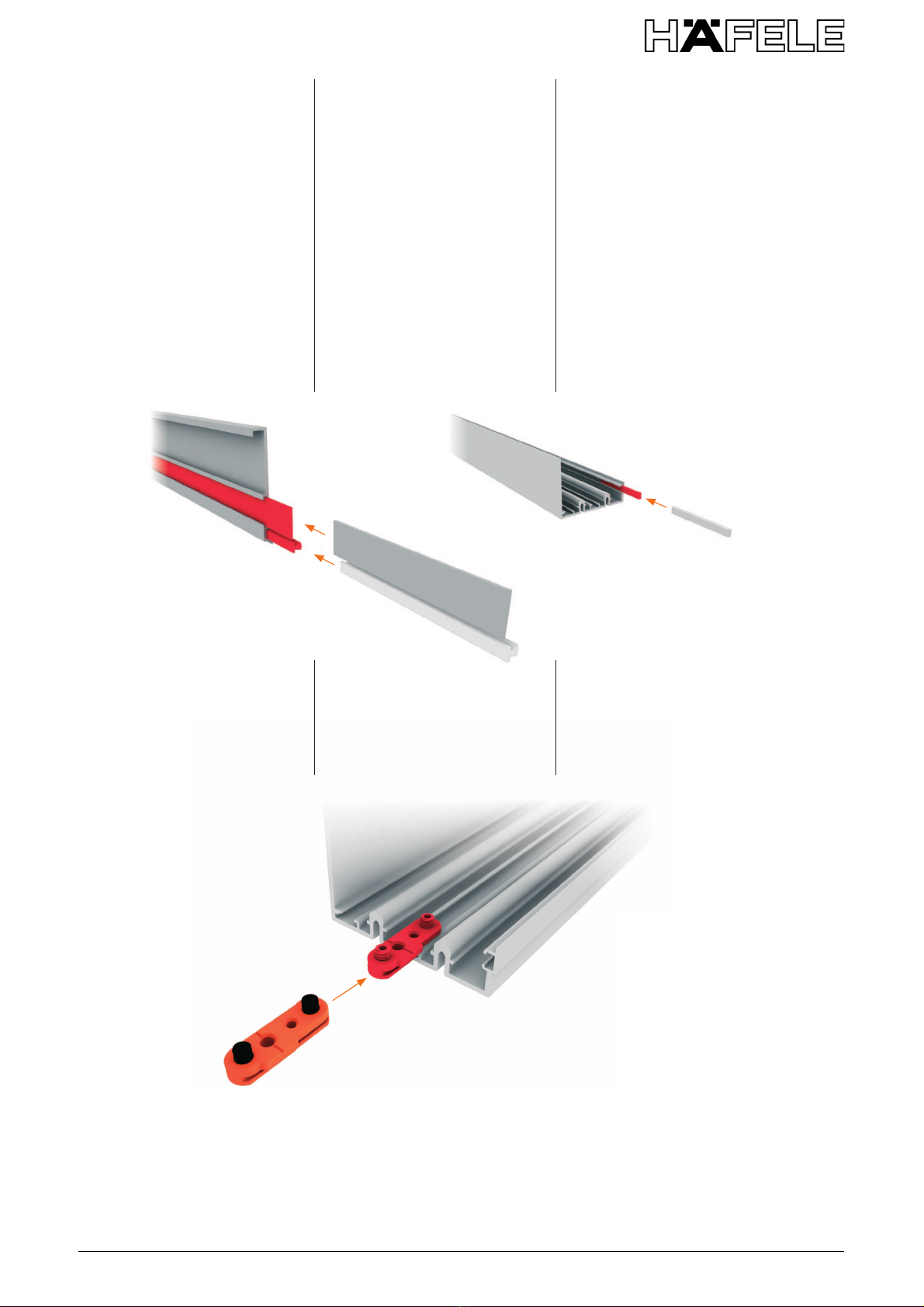
Preparazione binari
Preparare gli arresti superiori
(o gli stopper nel caso di ante
non ammortizzate) piegandoli,
inserendo la vite TCEI M5x14
(in dotazione) e avvitando par-
zialmente il dado M5 (in dota-
zione).
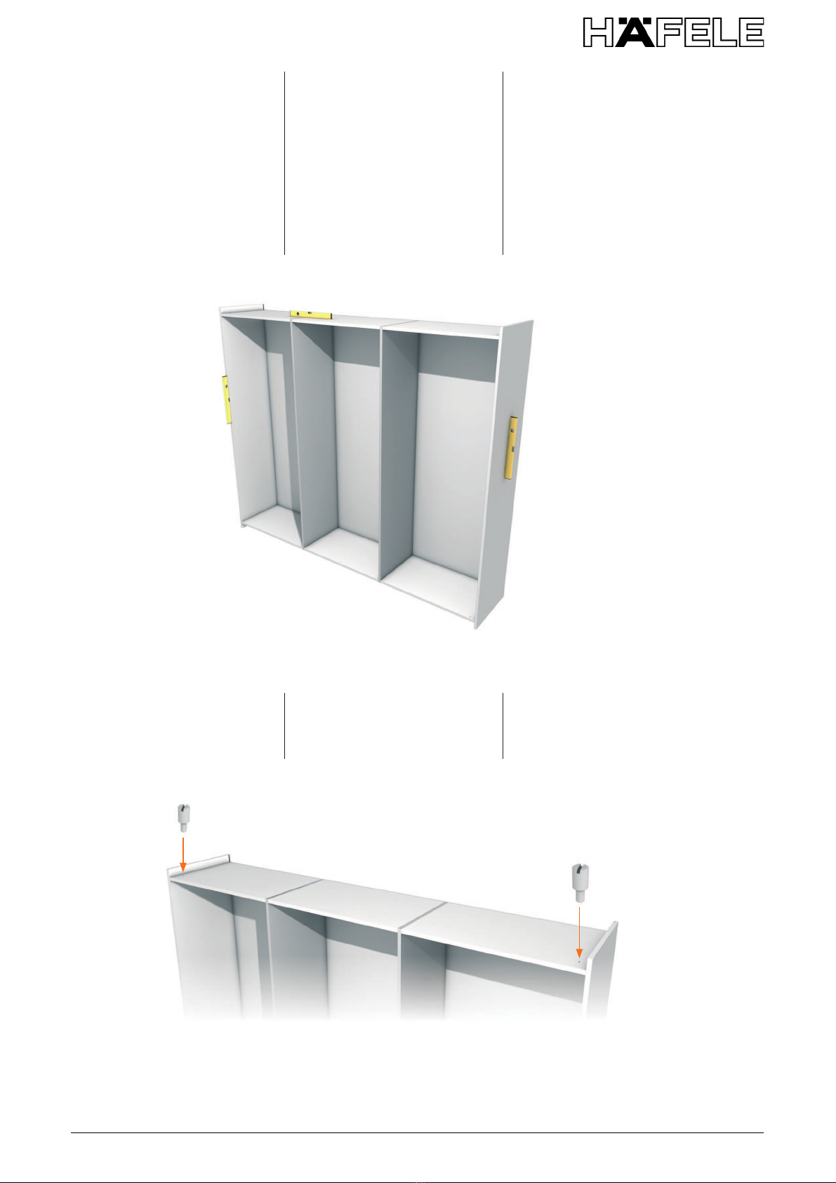
Applicare, liberi nei binari, n.
2 arresti superiori (o stopper -
Fig. 5) e n. 2 arresti inferiori (Fig.
6) per ciascuna anta.
A questa regola fa eccezione
l'armadio a 3 ante dove per le
2 ante interne è prevista l'appli-
cazione dell'arresto superiore
(o stopper) e inferiore solo nella
fase di chiusura.
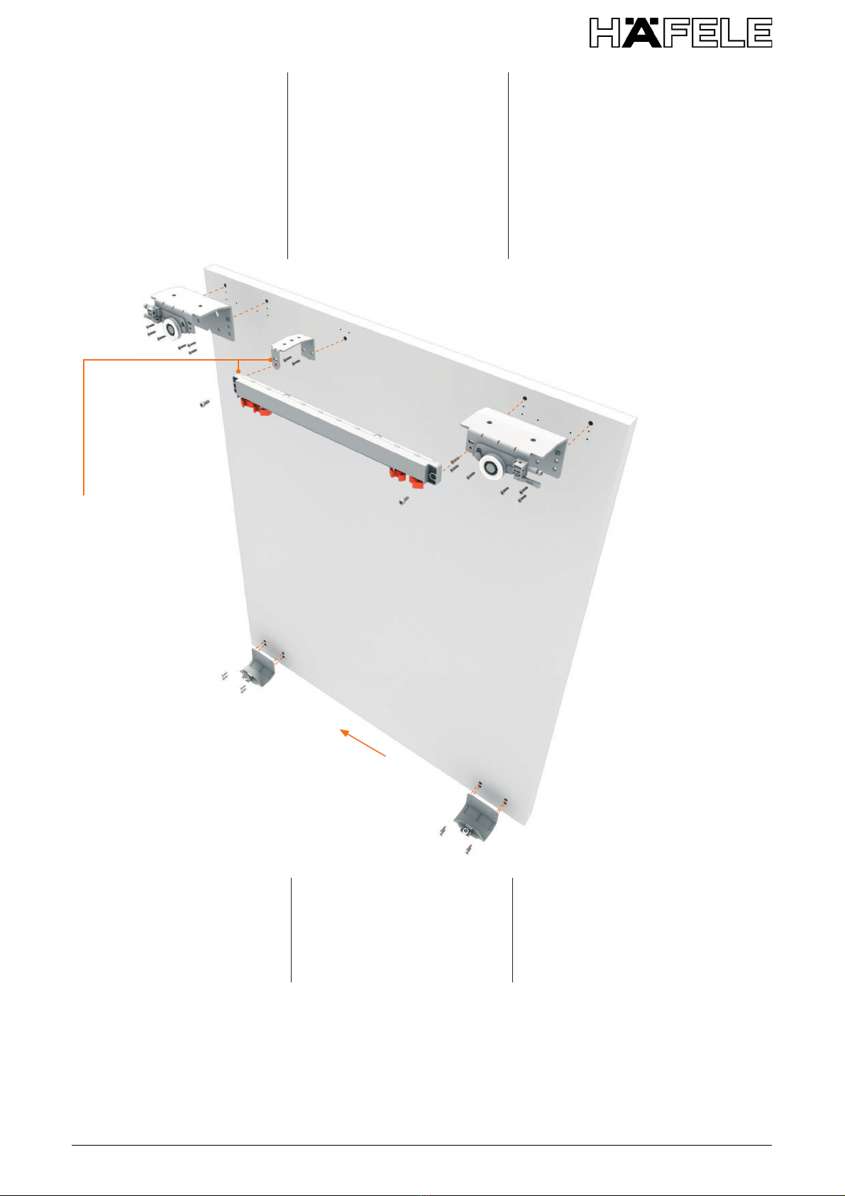
Attenzione: gli arresti supe-
riori (o stopper) devono essere
contrapposti e con il gommino
rivolto verso l'anta.
Assembly and
adjustments
Montage und
Einstellung
Preparation of tracks
Prepare the upper stoppers (or
the stoppers for doors without
shock absorbers) by bend-
ing them, inserting the screws
TCEI M5x14 (provided) and
partially tightening the nut M5
(provided).
Apply, free in the tracks, 2 up-
per stoppers (or stoppers - Fig.
5) and 2 lower stoppers (Fig. 6)
for each door.
The exception to this rule is a
3 door wardrobe, where for the
2 internal doors it is necessary
to apply an upper stopper (or
stopper) and lower stopper
only when closing.
Attention: the upper stoppers
(or stoppers) must face one an-
other and the rubber part must
be turned towards the door.
Vorbereitung der Laufschienen
Die oberen Stopper vorberei-
ten (Ausführung für Türen mit
oder ohne Dämpfung): Zusam-
menklappen, Schraube TCEI
M5x14 (liegt bei) einstecken
und die Mutter M5 (liegt bei)
teilweise festschrauben.
Für jede Tür 2 obere Stopper (Abb.
5) und 2 untere Stopper (Abb. 6)
anbringen, diese können sich frei
in der Laufschiene bewegen.
Eine Ausnahme gilt für den
Schrank mit 3 Türen, bei dem
für die 2 Innentüren die Anbrin-
gung des unteren und oberen
Stoppers nur für das Schließen
vorgesehen ist.
Achtung: Die oberen Stopper
müssen gegenüber liegend
angebracht werden, mit dem
Gummi in Schrankrichtung.
Fig. 5
Abb. 5
Fig. 6
Abb. 6