Domo DBS Nano PRO TX User manual

Resource Identifier: 100325
Revision 1.0
DBS Nano PRO Transmitter User
Guide
Commercial in Confidence

Revision: 1.0
DBS Nano PRO Transmitter User Guide
Copyright © 2022 Domo Tactical Communications (DTC) Limited. All rights reserved.
Commercial in Confidence
Page 0-1
0. Preface
0.1 About this Document
This document contains relevant information required to identify, install, and control the equipment or
system.
Since the available functions can be licensed and depend on the specific implementation, not all the
functions and or applications contained in this document may be relevant or applicable to the system
you will be working with.
The actual presentation may differ from those in this document due to hardware or software changes.
0.2 Intended Audience
This document is for anyone interested in how the system can be used, but it is of most benefit to:
Operators who oversee the daily operation of the equipment
Installers who are responsible for the pre-installation, on-site installation, and configuration of the
system in the end-user environment
Maintainers who are responsible for maintaining the equipment or system
0.3 Notice about this Publication
While every attempt is made to maintain the accuracy of the information in this product manual, it is
subject to change without notice.
Performance specifications are included for guidance. All particulars are given in good faith, actual
performance may vary.
0.4 Text Conventions
This document uses these conventions to identify text that has a special meaning:
Description
Example
Text in capitals represents a key press on a keyboard.
The + sign means hold down the first key and press the second key.
ESC, F1, SHIFT
CTRL+C
<Text> Serves as a placeholder for variable text that is replaced as
appropriate, the text may be written in italics.
Use the filename
<system_name>.sys for…
Text in italics can represent a link to a place in the existing document
(often these are hyperlinks) or a reference to another document.
Refer to Section 0.4, Text
Conventions.
Text in bold emphasises a term of significance.
We call this a protocol and
its function is…
Successive software menu selections are shown using arrows to
indicate sub-menus. This is often shown in bold.
Select Advanced>Audio
then edit…

Revision: 1.0
DBS Nano PRO Transmitter User Guide
Copyright © 2022 Domo Tactical Communications (DTC) Limited. All rights reserved.
Commercial in Confidence
Page 0-2
0.5 Symbols
These symbols are used to highlight important information.
WARNING: A notice of when a situation may result in personal injury or loss of life, or destruction of
equipment.
CAUTION: A notice of when a situation may result in loss of data or damage to equipment or systems.
Note: A notice to draw attention to something or to supply additional information.
0.6 Copyright
This document contains information that is proprietary to Domo Tactical Communications (DTC)
Limited trading as Domo Broadcast Systems (DBS). Any copying or reproduction in any form
whatsoever is prohibited without the written permission of DTC.
© 2022 Copyright Domo Tactical Communications (DTC) Limited. All rights reserved.
0.7 Document History
This is a controlled document, written and produced by the DTC Technical Publications team.
Changes are recorded in the table below.
Revision
Date
Author
Summary of Changes
1.0
08/12/2022
IR
First release

Revision: 1.0
DBS Nano PRO Transmitter User Guide
Copyright © 2022 Domo Tactical Communications (DTC) Limited. All rights reserved.
Commercial in Confidence
Page 0-3
CONTENTS
0. Preface........................................................................................0-1
0.1 About this Document ............................................................................................................0-1
0.2 Intended Audience................................................................................................................0-1
0.3 Notice about this Publication................................................................................................0-1
0.4 Text Conventions..................................................................................................................0-1
0.5 Symbols................................................................................................................................0-2
0.6 Copyright ..............................................................................................................................0-2
0.7 Document History.................................................................................................................0-2
1. Product Overview ........................................................................1-1
1.1 Description............................................................................................................................1-1
1.2 Basic Specifications..............................................................................................................1-1
1.3 Approval Notices ..................................................................................................................1-1
2. Product Package .........................................................................2-2
2.1 Overview...............................................................................................................................2-2
2.2 Parts List...............................................................................................................................2-2
2.3 Accessory Options................................................................................................................2-2
2.4 Licensing Options.................................................................................................................2-3
2.5 Variants.................................................................................................................................2-3
3. Connections, Controls, and Indicators .........................................3-4
3.1 Introduction...........................................................................................................................3-4
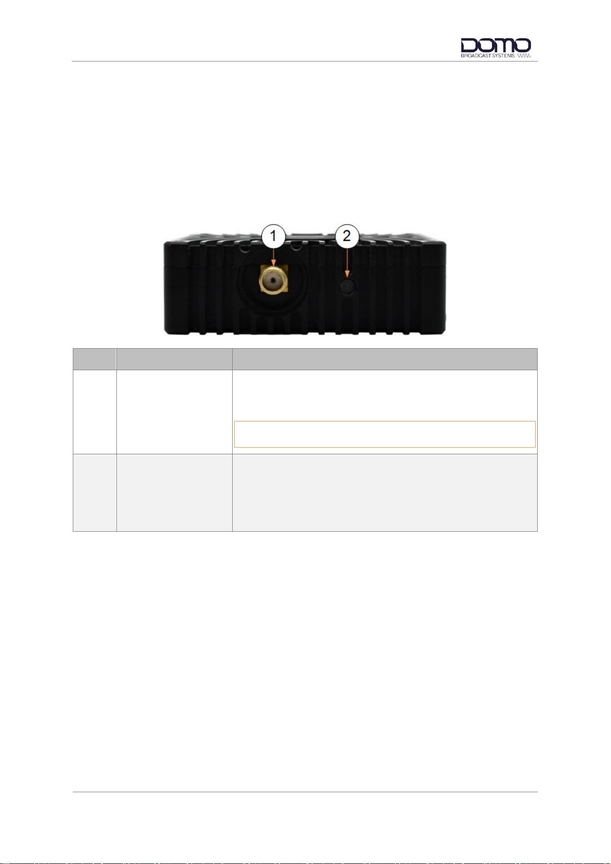
3.2 Antenna Panel......................................................................................................................3-4
3.3 Bottom Panel........................................................................................................................3-5
3.4 OLED Display and Control ...................................................................................................3-6
3.5 USB Micro.............................................................................................................................3-6
3.6 Antenna Adaptor / Camera Mount Bracket ..........................................................................3-7
3.7 Battery Mount Clamshell ......................................................................................................3-8
3.8 Pinout....................................................................................................................................3-9
4. Getting Started ..........................................................................4-11
4.1 Introduction.........................................................................................................................4-11
4.2 Power..................................................................................................................................4-11
4.3 Control................................................................................................................................4-11
4.4 Device Controller................................................................................................................4-12
5. Device Controller Operation.......................................................5-14
5.1 Introduction.........................................................................................................................5-14
5.2 Primary Page......................................................................................................................5-14
5.3 Advanced>Unit Page..........................................................................................................5-16
5.4 Advanced>Modulation Page ..............................................................................................5-18
5.5 Advanced>Audio Page.......................................................................................................5-21
5.6 Advanced>Video Page.......................................................................................................5-23
5.7 Advanced>Misc Page.........................................................................................................5-26
5.8 Upload Page.......................................................................................................................5-29
6. OLED Display Control................................................................6-30
6.1 Introduction.........................................................................................................................6-30
6.2 Control Buttons...................................................................................................................6-30
6.3 OLED Display Menu...........................................................................................................6-31

Revision: 1.0
DBS Nano PRO Transmitter User Guide
Copyright © 2022 Domo Tactical Communications (DTC) Limited. All rights reserved.
Commercial in Confidence
Page 0-4
6.4 OLED Display Upgrade ......................................................................................................6-36
7. Appendix A –Reference Material ..............................................7-38
7.1 dBm to Watts Conversion...................................................................................................7-38
7.2 Software Upgrade via a Terminal Program........................................................................7-39
8. Appendix B –After Sales Support..............................................8-40
8.1 Documentation and Software.............................................................................................8-40
8.2 Contact Technical Support.................................................................................................8-40
8.3 Using the DTC RMA Service..............................................................................................8-40
9. Appendix C –Safety and Maintenance......................................9-42
9.1 Cautions and Warnings ......................................................................................................9-42
9.2 Repairs and Alterations ......................................................................................................9-43
9.3 Caring for your Equipment..................................................................................................9-43
9.4 Charging.............................................................................................................................9-43
9.5 Working with Lithium Batteries...........................................................................................9-43
9.6 Cleaning..............................................................................................................................9-44
9.7 Storage...............................................................................................................................9-44

Revision: 1.0
DBS Nano PRO Transmitter User Guide
Copyright © 2022 Domo Tactical Communications (DTC) Limited. All rights reserved.
Commercial in Confidence
Page 1-1
1. Product Overview
1.1 Description
DBS has built upon the outstanding features of the award-winning DTC NanoHD TX to create the
ultimate PoV miniature broadcast transmitter.
The DBS Nano PRO Transmitter is an ultra-miniature COFDM digital video transmitter, designed
specifically for Point-of-View (PoV) and body-worn applications.
With proven DTC COFDM and H.264 encoder technology at its core, exceptionally small size, and
ultra-low power consumption (typically 7W), the DBS Nano PRO TX enables production teams to offer
viewers stunning high-definition images from the heart of the action, in situations never previously
possible due to equipment size and battery run-time constraints.
The small size and ultra-low power consumption make the DBS Nano PRO TX ideal for UAV
Octocopter installations, enabling true long range HD broadcasting from these increasingly popular
devices for the first time. Optional lightweight, low power consumption amplifiers are also available for
even greater range capability.
The transmitter employs ultra-low latency High Profile H.264 (MPEG-4 AVC) encoding for excellent
image quality retention over the wireless link and supports SDI and HD-SDI video input formats up to
1080p50/59.
The DBS Nano PRO TX is supplied in a slimline, fan-cooled, aluminium lightweight case and features
industry standard connectors for RF (SMA), video (BNC), power/data (Hirose), audio (Hirose) and
control (mini-USB). An integrated joystick control panel and OLED display are provided for control and
monitoring of all parameters.
1.2 Basic Specifications
DC Input
6V to 17V DC reverse polarity protected
Power consumption
HD encoding –7.5W worse case with 100mW RF power
Temperature range
-10°C to +50°C
Dimensions
18mm (h) x 60mm (w) x 63.5mm (d)
Weight
125g
Note: Detailed technical specifications are given in the product datasheet. Please contact DBS for
latest specifications.
1.3 Approval Notices
1.3.1 EMC/Safety and CE Marking
The equipment has been designed to meet and has been tested against harmonized EMC and safety
standards. The CE Declaration of Conformity as well as the technical file are available on request.

Revision: 1.0
DBS Nano PRO Transmitter User Guide
Copyright © 2022 Domo Tactical Communications (DTC) Limited. All rights reserved.
Commercial in Confidence
Page 2-2
2. Product Package
2.1 Overview
Carefully open the packaging and verify that all the parts have been included, as ordered. Retain the
packing materials for storage.
The part numbers are useful for identification and if you need to order a new part. The part number
codes mean:
CA –cable assembly
SA –sub assembly
AP –assembly part
Note: If you do not have all the parts or are not happy with the condition of your delivered product,
please contact DTC. See Section 8.2.
2.2 Parts List
These items will be in the package.
Part Number
Description
Primary Unit
DBS Nano PRO Transmitter (see variants Section 2.5)
CAB0008
XLR analogue audio cable
CAB0009
Power and control cable
2.3 Accessory Options
If you have purchased any of these items, they will also be in the package.
Part Number
Description
BAMP-1W-200250
Barrel Booster Amplifier 1W 2.00-2.50GHz
BAMP-1W-320360
Barrel Booster Amplifier 1W 3.20-3.60GHz
BAMP-1W-440500
Barrel Booster Amplifier 1W 4.40-5.00GHz
BAMP-1W-550600
Barrel Booster Amplifier 1W 5.50-6.00GHz
BAMP-1W-640700
Barrel Booster Amplifier 1W 6.40-7.00GHz
BAMP-1W-700750
Barrel Booster Amplifier 1W 7.00-7.50GHz
BRK-NPRO-NTYPE
Nano PRO antenna adapter bracket
BRK-NPRO-VLAB-AB
Nano PRO AB-mount clamshell
BRK-NPRO-VLAB-V
Nano PRO V-mount clamshell

Revision: 1.0
DBS Nano PRO Transmitter User Guide
Copyright © 2022 Domo Tactical Communications (DTC) Limited. All rights reserved.
Commercial in Confidence
Page 2-3
2.4 Licensing Options
Some product functions are enabled by licenses. The license for your product can be viewed in the
control software.
Standard Licenses
DVB-T Modulation
UMVL (Ultra Mobile Video Link) Modulation
HD H.264 Encoding
Optional Licenses
4:2:2 H.264 Profile
Dual Pedestal
SDI Ancillary Data
2.5 Variants
This part number will identify the product; it is also on the label.
Part Number
Description
DBSNPROTX-198270
DBS Nano PRO Transmitter 1.98-2.70GHz
DBSNPROTX-300370
DBS Nano PRO Transmitter 3.00-3.70GHz
DBSNPROTX-440500
DBS Nano PRO Transmitter 4.40-5.00GHz
DBSNPROTX-550600
DBS Nano PRO Transmitter 5.50-6.00GHz
DBSNPROTX-650700
DBS Nano PRO Transmitter 6.50-7.00GHz
DBSNPROTX-680730
DBS Nano PRO Transmitter 6.80-7.30GHz
DBSNPROTX-700750
DBS Nano PRO Transmitter 7.00-7.50GHz

Revision: 1.0
DBS Nano PRO Transmitter User Guide
Copyright © 2022 Domo Tactical Communications (DTC) Limited. All rights reserved.
Commercial in Confidence
Page 3-4
3. Connections, Controls, and Indicators
3.1 Introduction
This chapter will help identify all the connections and interfaces of the product needed to install,
control, and monitor the device.
3.2 Antenna Panel
No.
Item
Connection
1
SMA jack (female)
RF power output.
Ensure power output is not enabled before attaching the
antenna.
CAUTION: Antenna should be finger tight only to avoid damage
to the connector or internal components.
2
RF Status LED
Tri-colour LED indicator.
Amber = booting
Red = RF output off
Green = RF output on

Revision: 1.0
DBS Nano PRO Transmitter User Guide
Copyright © 2022 Domo Tactical Communications (DTC) Limited. All rights reserved.
Commercial in Confidence
Page 3-5
3.3 Bottom Panel
No.
Item
Connection
1
BNC jack (female)
See note below.
HD/SD-SDI video input. Can also be configured as an ASI input.
2
Video Status LED
Tri-colour LED indicator.
Amber = booting
Red = no video input lock
Green = video input locked
3
6-way Hirose (female)
Analogue audio left/right input. See Section 3.8.1 for pinout.
CAB0008 provides two XLR connections for an audio source.
4
6-way Hirose (male)
Power, data, and control input. See Section 3.8.2 for pinout.
CAB0009 provides an XLR connection for a power source and a
DB9 for control.
BNC Interface Note
The BNC input connector is a changeable screw-fit interface. This can be swapped for a DIN1.0/2.3
interface or a Micro BNC interface available from https://www.cambridgeelectronics.com/. Part
numbers are given below:
XKT-8014-GGA –DIN1.0/2.3 interface
XKT-D000-GGAY –Micro BNC interface

Revision: 1.0
DBS Nano PRO Transmitter User Guide
Copyright © 2022 Domo Tactical Communications (DTC) Limited. All rights reserved.
Commercial in Confidence
Page 3-6
3.4 OLED Display and Control
No.
Item
Connection
1
Fan outlet
Air outlet to aid cooling of the Nano PRO TX internal components.
CAUTION: Do not obstruct or allow any objects to enter this space.
2
OLED display
Integrated display screen for status and control of commonly used
parameters.
See Chapter 6 for description of operation.
3
Control button
OLED display cancel/back button.
4
Control button
OLED display navigation/select/edit button.
3.5 USB Micro
On the side panel there is a USB-micro control port socket for configuring the unit using the Device
Controller application.
Connect a USB-micro to USB type A cable from the Nano PRO TX to a PC or laptop.

Revision: 1.0
DBS Nano PRO Transmitter User Guide
Copyright © 2022 Domo Tactical Communications (DTC) Limited. All rights reserved.
Commercial in Confidence
Page 3-7
3.6 Antenna Adaptor / Camera Mount Bracket
The optional antenna adaptor bracket allows the SMA socket to be adapted to an N-type socket for
antennas with N-type connectors as illustrated in Figure 3-1.
Figure 3-1: Bracket Showing N-Type Adaptor
The optional antenna adaptor bracket also has a Hot Shoe wedge to allow the Nano PRO TX to mount
to any camera with this fitting as illustrated in Figure 3-2.
Figure 3-2: Bracket Showing Camera Mount

Revision: 1.0
DBS Nano PRO Transmitter User Guide
Copyright © 2022 Domo Tactical Communications (DTC) Limited. All rights reserved.
Commercial in Confidence
Page 3-8
3.7 Battery Mount Clamshell
DBS offer a clamshell housing accessory which will allow the Nano PRO TX to be mounted to a
camera battery, see Section 2.3. An illustration of a V-mount clamshell is given in Figure 3-2.
If this is a requirement, please contact DBS to arrange assembly and integration.
Figure 3-3: Nano PRO TX Clamshell –V-Mount Option

Revision: 1.0
DBS Nano PRO Transmitter User Guide
Copyright © 2022 Domo Tactical Communications (DTC) Limited. All rights reserved.
Commercial in Confidence
Page 3-9
3.8 Pinout
3.8.1 AUDIO
Nano Tx
Hirose 6-way receptacle (female) –HR10-7R-6S(73).
Pin
Function
1
Audio Left+
2
Audio Left-
3
Gnd
4
Audio Right+
5
Audio Right-
6
Gnd
CAB0008
Hirose 6-way plug (male) –HR10-7P-6P(73)
Pin
Function
1
Audio Left+
2
Audio Left-
3
Gnd
4
Audio Right+
5
Audio Right-
6
Gnd
3-way XLR (female) x 2 –RS 405-590
Pin
Function
1
Audio Left/Right+
2
Audio Left/Right-
3
Gnd

Revision: 1.0
DBS Nano PRO Transmitter User Guide
Copyright © 2022 Domo Tactical Communications (DTC) Limited. All rights reserved.
Commercial in Confidence
Page 3-10
3.8.2 PWR
Nano Tx
Hirose 6-way receptacle (male) –HR10-7R-6P(73).
Pin
Function
1
Gnd
2
Vout (12V)
3
RS-232 Data Rx
4
Vin (6-17VDC, 12V nom.)
5
RS-232 Ctrl Tx
6
RS-232 Ctrl Rx
CAB0009
Hirose 6-way plug (female) –HR10-7P-6S(73)
Pin
Function
1
Gnd
2
Vout (12V)
3
RS-232 Data Rx
4
Vin (6-17VDC, 12V nom.)
5
RS-232 Ctrl Tx
6
RS-232 Ctrl Rx
4-way XLR (male) –RS 457-869
Pin
Function
1
Gnd
4
Vin (6-17VDC, 12V nom.)
9-way D-sub (female) –RS 765-9555
Pin
Function
2
RS-232 Ctrl Tx
3
RS-232 Ctrl Rx
5
Gnd

Revision: 1.0
DBS Nano PRO Transmitter User Guide
Copyright © 2022 Domo Tactical Communications (DTC) Limited. All rights reserved.
Commercial in Confidence
Page 4-11
4. Getting Started
4.1 Introduction
This chapter will help the user power up and communicate with their product. It will explain software
installation instructions for any relevant applications.
4.2 Power
DBS Nano PRO TX does not have a power switch, it is powered up as soon as the power source is
connected. Before removing power, ensure the device is not in sleep mode, see Section 5.3.1.
4.3 Control
The Nano PRO TX can be controlled via the OLED display explained in detail in Chapter 6, or via
Device Controller explained below and in detail in Chapter 5.

Revision: 1.0
DBS Nano PRO Transmitter User Guide
Copyright © 2022 Domo Tactical Communications (DTC) Limited. All rights reserved.
Commercial in Confidence
Page 4-12
4.4 Device Controller
4.4.1 Introduction
Device Controller is a desktop application which allows control and monitoring of the device. Device
Controller allows you to set up to sixteen presets and have control of all parameters of the unit.
4.4.2 Installation
Device Controller comes as an executable installer package which is available from DTC’s Watchdox
facility, see Section 8.1.
Double-click the executable and follow prompts as directed to install this application on your PC.
On successful installation a desktop shortcut will be placed on your desktop.
4.4.3 Communications
Ensure your transmitter is powered up and connected to a PC by USB or serial using CAB0009.
IMPORTANT: If using serial communications, you must enter Remote Control mode from the OLED
display, see Section 6.3.4.
Double-click the Device Controller desktop shortcut on the PC to open the application and click the
connection button.

Revision: 1.0
DBS Nano PRO Transmitter User Guide
Copyright © 2022 Domo Tactical Communications (DTC) Limited. All rights reserved.
Commercial in Confidence
Page 4-13
Select the device connection depending on the physical interface and select the USB ID number or
serial port com port as applicable.
Click Connect to establish communications. Device Controller reads the Nano PRO TX settings and
opens the primary page.

Revision: 1.0
DBS Nano PRO Transmitter User Guide
Copyright © 2022 Domo Tactical Communications (DTC) Limited. All rights reserved.
Commercial in Confidence
Page 5-14
5. Device Controller Operation
5.1 Introduction
The Nano PRO TX uses the Device Controller application on your PC to provide detailed control and
monitoring. Device Controller will enable you to get the most from your transmitter.
IMPORTANT: Not all settings and views in Device Controller will be applicable to the DBS Nano PRO
TX. Only applicable settings will be explained in this chapter.
If the Device Controller menu shows a ‘lock’ symbol next to a feature, this means that it is not
available for your device or that it is missing a license.
5.2 Primary Page
The Primary page allows quick configuration of key parameters without needing to go to the Advanced
setup pages.
5.2.1 Presets
Up to sixteen preset configurations can be stored. The blue button is the currently active preset.

Revision: 1.0
DBS Nano PRO Transmitter User Guide
Copyright © 2022 Domo Tactical Communications (DTC) Limited. All rights reserved.
Commercial in Confidence
Page 5-15
5.2.2 Configuration Settings
The configuration settings allow you to make changes to key RF, video, and audio settings without
needing to go to the Advanced pages.
The range mode and video quality sliders will auto-adjust advanced modulation or video settings
according to a sliding scale.
5.2.3 Unit Status
Colour-coded indicators are provided to show RF power, video, audio, and temperature status.
The RF icon on the left of the panel will allow you to quickly set RF power on or off.
The green connection icon on the left of the panel provides a quick disconnect option without any
warnings.
5.2.4 Swich Panel
The switch panel provides access to Advanced settings, Engineer options, Upload options and Quit
application.
The Advanced pages give access to the preset configurations for the Nano PRO TX. These pages
are explored in detail in the following sections.
The Engineer pages give access to diagnostics and save options. These pages are for DBS
engineering and should only be accessed by advanced users.
The Upload page details how to upgrade the Nano PRO TX software or licenses, see Section 5.8 for
details. Upgrade files will be provided by DBS.
This manual suits for next models
7
Table of contents
Other Domo Transmitter manuals