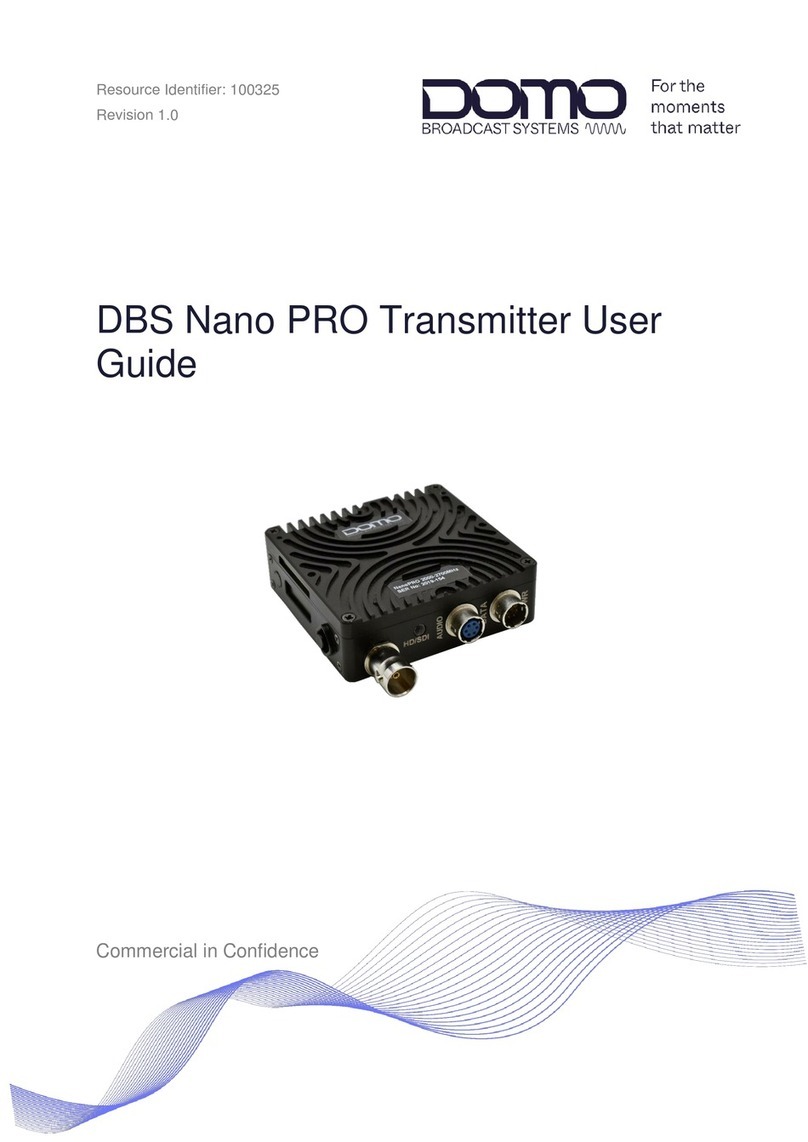
Domo Sapphire-BTX User manual

Resource Identifier: 100322
Revision 1.0
Sapphire-BTX Setup Guide
Commercial in Confidence

Revision: 1.0
Sapphire-BTX Setup Guide
Copyright © 2022 Domo Tactical Communications (DTC) Limited. All rights reserved.
Commercial in Confidence
Page 0-1
0. Preface
0.1 About this Document
This document contains relevant information required to identify, install and control the equipment or
system.
Since the available functions can be licensed and depend on the specific implementation, not all the
functions and or applications contained in this document may be relevant or applicable to the system
you will be working with.
The actual presentation may differ from those in this document due to hardware or software changes.
0.2 Intended Audience
This document is for anyone interested in how the system can be used, but it is of most benefit to:
Operators who oversee the daily operation of the equipment
Installers who are responsible for the pre-installation, on-site installation, and configuration of the
system in the end-user environment
Maintainers who are responsible for maintaining the equipment or system
0.3 Notice about this Publication
While every attempt is made to maintain the accuracy of the information in this product manual, it is
subject to change without notice.
Performance specifications are included for guidance. All particulars are given in good faith, actual
performance may vary.
0.4 Text Conventions
This document uses these conventions to identify text that has a special meaning:
Description Example
Text in capitals represents a key press on a keyboard.
The + sign means hold down the first key and press the second key.
ESC, F1, SHIFT
CTRL+C
<Text> Serves as a placeholder for variable text that is replaced as
appropriate, the text may be written in italics.
Use the filename
<system_name>.sys for…
Text in italics can represent a link to a place in the existing document
(often these are hyperlinks) or a reference to another document.
Refer to Section 0.4, Text
Conventions.
Text in bold emphasises a term of significance. We call this a protocol and
its function is…
Successive software menu selections are shown using arrows to
indicate sub-menus. This is often shown in bold.
Select Presets>Streamers
then edit…

Revision: 1.0
Sapphire-BTX Setup Guide
Copyright © 2022 Domo Tactical Communications (DTC) Limited. All rights reserved.
Commercial in Confidence
Page 0-2
0.5 Symbols
These symbols are used to highlight important information.
WARNING: A notice of when a situation may result in personal injury or loss of life, or destruction of
equipment.
CAUTION: A notice of when a situation may result in loss of data or damage to equipment or systems.
Note: A notice to draw attention to something or to supply additional information.
0.6 Copyright
This document contains information that is proprietary to Domo Tactical Communications (DTC)
Limited trading as Domo Broadcast Systems (DBS). Any copying or reproduction in any form
whatsoever is prohibited without the written permission of DTC.
© 2022 Copyright Domo Tactical Communications (DTC) Limited. All rights reserved.
0.7 Related Documents
All DTC documents can be downloaded from WatchDox, see Section 8.1.
Document Source
MASH Serial Guide Describes the serial control protocol
MASH REST API Guide Describes the REST API control over IP
MASH Schemas Guide Explains the contents of schemas from the unit.
Schemas are used to generate all the status/config/command web
pages, options, help text etc.
0.8 Document History
This is a controlled document, written and produced by the DTC Technical Publications team.
Changes are recorded in the table below.
Revision Date Author Summary of Changes
1.0 28/09/2022 IR First draft

Revision: 1.0
Sapphire-BTX Setup Guide
Copyright © 2022 Domo Tactical Communications (DTC) Limited. All rights reserved.
Commercial in Confidence
Page 0-3
CONTENTS
0. Preface ........................................................................................0-1
0.1 About this Document ............................................................................................................ 0-1
0.2 Intended Audience................................................................................................................ 0-1
0.3 Notice about this Publication ................................................................................................ 0-1
0.4 Text Conventions.................................................................................................................. 0-1
0.5 Symbols ................................................................................................................................ 0-2
0.6 Copyright .............................................................................................................................. 0-2
0.7 Related Documents .............................................................................................................. 0-2
0.8 Document History ................................................................................................................. 0-2
1. Product Overview ........................................................................1-1
1.1 Description............................................................................................................................ 1-1
1.2 Basic Specifications.............................................................................................................. 1-1
1.3 Approval Notices .................................................................................................................. 1-1
2. Product Package .........................................................................2-2
2.1 Overview............................................................................................................................... 2-2
2.2 Parts List............................................................................................................................... 2-2
2.3 Variants................................................................................................................................. 2-2
2.4 Camera Control Options....................................................................................................... 2-3
2.5 Licensing............................................................................................................................... 2-3
3. Connections, Controls, and Indicators .........................................3-4
3.1 Introduction ........................................................................................................................... 3-4
3.2 Bottom Panel ........................................................................................................................ 3-4
3.3 Top Panel ............................................................................................................................. 3-5
3.4 Data Panel ............................................................................................................................ 3-6
3.5 LED Display Panel................................................................................................................ 3-7
3.6 Pinout.................................................................................................................................... 3-8
4. LED Display Control ..................................................................4-10
4.1 Power.................................................................................................................................. 4-10
4.2 Introduction ......................................................................................................................... 4-10
4.3 Control Buttons ................................................................................................................... 4-11
4.4 LED Display Menus ............................................................................................................ 4-11
5. Web Browser Control.................................................................5-13
5.1 Power.................................................................................................................................. 5-13
5.2 Introduction ......................................................................................................................... 5-13
5.3 IP Address Identification..................................................................................................... 5-14
5.4 Open the Web Interface ..................................................................................................... 5-15
5.5 Status Page ........................................................................................................................ 5-16
5.6 Config Pages ...................................................................................................................... 5-17
5.7 Unit Page ............................................................................................................................ 5-22
5.8 Upgrade Page..................................................................................................................... 5-23
5.9 Presets Page ...................................................................................................................... 5-23
5.10 Info Page ............................................................................................................................ 5-24
6. Basic Setup Guide .....................................................................6-25
6.1 Introduction ......................................................................................................................... 6-25
6.2 Video Setup ........................................................................................................................ 6-25

Revision: 1.0
Sapphire-BTX Setup Guide
Copyright © 2022 Domo Tactical Communications (DTC) Limited. All rights reserved.
Commercial in Confidence
Page 0-4
6.3 RF Setup............................................................................................................................. 6-26
7. Appendix A – Reference Material ..............................................7-27
7.1 How to Configure a PC IP Address .................................................................................... 7-27
7.2 dBm to Watts Conversion................................................................................................... 7-28
8. Appendix B – After Sales Support..............................................8-29
8.1 Documentation and Software ............................................................................................. 8-29
8.2 Contact Technical Support ................................................................................................. 8-29
8.3 Using the DTC RMA Service .............................................................................................. 8-29
9. Appendix C – Safety and Maintenance ......................................9-31
9.1 Cautions and Warnings ...................................................................................................... 9-31
9.2 Repairs and Alterations ...................................................................................................... 9-31
9.3 Caring for your Equipment.................................................................................................. 9-32
9.4 Charging ............................................................................................................................. 9-32
9.5 Working with Lithium Batteries ........................................................................................... 9-32
9.6 Cleaning.............................................................................................................................. 9-33
9.7 Storage ............................................................................................................................... 9-33

Revision: 1.0
Sapphire-BTX Setup Guide
Copyright © 2022 Domo Tactical Communications (DTC) Limited. All rights reserved.
Commercial in Confidence
Page 1-1
1. Product Overview
1.1 Description
The Sapphire Broadcast Transmitter (Sapphire-BTX) integrates a true 4K HEVC encoder with a
COFDM modulator creating a single, compact package, suitable for camera-back mounting.
The Sapphire-BTX is equipped with a single video input capable of 3G HD-SDI, 6G and 12G, thus
allowing video formats to UHD.
Back-to-back V-Lock or Anton Bauer battery plates facilitate pass-through power whilst an additional
external power connector is provided at the base. Analogue stereo audio inputs are supported as well
as camera control and Tally interfaces. An ASI transport stream interface is provided to facilitate easy
connection to other modulation systems.
Sapphire-BTX is equipped with a high-quality, low-latency H.265 (H.264 is also available) encoder
capable of UHD and HD formats in 10bit 4:2:2 with automatic HDR support.
Up to 8 stereo pairs of audio in either MPEG-1 layer 1, or PCM format (4 stereo pairs in AAC-LC) can
be extracted and encoded by The Sapphire-BTX whilst analogue audio inputs with power are included
for direct microphone connection.
Camera control and transmitter settings are accessible through a single colour panel on the side or
using the web browser interface.
Bi-directional camera control is a hardware option in the Sapphire-BTX.
1.2 Basic Specifications
DC Input 9-36VDC
Power consumption 25W typical @ 4K encoding
Temperature range -10 to +50°C
Dimensions 155mm x 95mm x 33mm
Weight 500g
Note: Detailed technical specifications are given in the product datasheet. Please contact DBS for
latest specifications.
1.3 Approval Notices
1.3.1 EMC/Safety and CE Marking
The equipment has been designed to meet and has been tested against harmonized EMC and safety
standards. The CE Declaration of Conformity as well as the technical file are available on request.

Revision: 1.0
Sapphire-BTX Setup Guide
Copyright © 2022 Domo Tactical Communications (DTC) Limited. All rights reserved.
Commercial in Confidence
Page 2-2
2. Product Package
2.1 Overview
Carefully open the packaging and verify that all the parts have been included, as ordered. Retain the
packing materials for storage.
Note: If you do not have all the parts or are not happy with the condition of your delivered product,
please contact DTC. See Section 8.2.
2.2 Parts List
These items will be in the package.
Part Number Description
Primary unit Sapphire Camera Back Transmitter (see variants below)
CAB0035 BTX power cable
CAB008 Stereo audio input cable
2.3 Variants
This part number will identify the product; it is also on the label.
Part Number Description
BTX-200270-AB Sapphire Camera Back TX 1980-2700MHz, AB battery mount
BTX-200270-V Sapphire Camera Back TX 1980-2700MHz, V-lock battery mount
BTX-310360-AB Sapphire Camera Back TX 3100-3600MHz, AB battery mount
BTX-310360-V Sapphire Camera Back TX 3100-3600MHz, V-lock mount battery
BTX-440500-AB Sapphire Camera Back TX 4400-5000MHz, AB battery mount
BTX-440500-V Sapphire Camera Back TX 4400-5000MHz, V-lock mount battery
BTX-550600-AB Sapphire Camera Back TX 5500-6000MHz, AB battery mount
BTX-550600-V Sapphire Camera Back TX 5500-6000MHz, V-lock mount battery

Revision: 1.0
Sapphire-BTX Setup Guide
Copyright © 2022 Domo Tactical Communications (DTC) Limited. All rights reserved.
Commercial in Confidence
Page 2-3
2.4 Camera Control Options
The Sapphire-BTX can include a camera control module. These are the camera control options which
can also be ordered as an upgrade.
Part Number Description
VS-CCCAM-ARRI-UP-SAP Hitachi camera control and cable
VS-CCCAM-GV-UP-SAP Grass Valley camera control and cable
VS-CCCAM-H-UP-SAP Hitachi camera control and cable
VS-CCCAM-I-UP-SAP Ikegami camera control and cable
VS-CCCAM-P-UP-SAP Panasonic camera control and cable
VS-CCCAM-S-UP-SAP Sony camera control and cable
2.5 Licensing
Some product functions are enabled by licenses. The license for your product can be viewed in the
control software, see Section 5.10.
Description Included/Optional
Encode Included
H.265 HEVC Included
H.264 AVC Included
MPEG-2 Included
UHD Optional
Ultra Low Latency Included
10-bit Included
4:2:2 Included
PsF Optional
DES Optional
BISS Optional
Recording Optional
IP Streaming Optional
MPEG-1 ULL Included
4KDCI Optional

Revision: 1.0
Sapphire-BTX Setup Guide
Copyright © 2022 Domo Tactical Communications (DTC) Limited. All rights reserved.
Commercial in Confidence
Page 3-4
3. Connections, Controls, and Indicators
3.1 Introduction
This chapter will help identify all the connections and interfaces of the product needed to install,
control, and monitor the device.
3.2 Bottom Panel
Note: See Section 3.6 for pinout.
No. Item Connection
1 RJ45 jack Gigabit Ethernet connection for web user interface control
and IP streaming.
2 Hirose 6-way (male) 9-36VDC input. Connect supplied CAB0035 BTX power
cable to a nominal 12V supply.
3 Hirose 6-way (female) CAB008 can connect here to provide a stereo analogue
audio input.
4 BNC socket (75Ω) SDI video input.
Supports 12G-SDI, 6G-SDI, or 3G-SDI video formats.
5 Video input LED Dual colour LED:
Red – no video lock
Green – video lock
6 BNC socket (75Ω) ASI video output.

Revision: 1.0
Sapphire-BTX Setup Guide
Copyright © 2022 Domo Tactical Communications (DTC) Limited. All rights reserved.
Commercial in Confidence
Page 3-5
3.3 Top Panel
No. Item Connection
1 N-type (female) RF out antenna connector.
2 LED The LED will flash when camera control data is received.
3 SMA (female) Camera control telemetry antenna connector.
Note: RF In will be non-functional for units without the camera
control option.

Revision: 1.0
Sapphire-BTX Setup Guide
Copyright © 2022 Domo Tactical Communications (DTC) Limited. All rights reserved.
Commercial in Confidence
Page 3-6
3.4 Data Panel
Note: See Section 3.6 for pinout.
No. Item Connection
1 On/off switch Controls power to the BTX only.
2 Hirose 10-way (male) This is the remote-control data input/output to the camera.
Note: Camera control will be non-functional for units without the
camera control option.
3 Hirose 4-way (female) Tally light connection.
Note: Tally will be non-functional for units without the camera
control option.
4 Hirose 6-way (male) Auxiliary data connector. Typically used to transmit GPS data
from an external device.

Revision: 1.0
Sapphire-BTX Setup Guide
Copyright © 2022 Domo Tactical Communications (DTC) Limited. All rights reserved.
Commercial in Confidence
Page 3-7
3.5 LED Display Panel
No. Item Connection
1 Button control Menu cancel/back button
2 LED display Display screen for status and control of the most used
parameters.
See Chapter 4for a description of operation.
3 Button control Menu navigation/select/edit button.
4 Power LED Power LED will illuminate when power is applied.
5 Status LED Tri-colour LED:
Red – no video lock, RF off
Amber – no video lock, RF on
Off – video lock, RF off
Green – video lock, RF on

Revision: 1.0
Sapphire-BTX Setup Guide
Copyright © 2022 Domo Tactical Communications (DTC) Limited. All rights reserved.
Commercial in Confidence
Page 3-8
3.6 Pinout
3.6.1 9-36V DC
Mating part: Hirose HR10-7P-6S(73)
Pin Function
1 VIN
2 VIN
3 VIN
4 GND
5 GND
6 GND
3.6.2 AUDIO
Mating part: Hirose HR10A-7P-6P(73)
Pin Function
1 AUDIO IN L+
2 AUDIO IN L-
3 GND
4 AUDIO IN R+
5 AUDIO IN R-
6 GND
3.6.3 CAMERA CONTROL
Mating part: Hirose HR10A-10P-10S(73)
Pin Function
1 CAM CTRL TX+ (RS422)
2 CAM CTRL TX- (RS422)
3 CAM CTRL RX+ (RS422)
4 CAM CTRL RX- (RS422)
5 GND
6 CAM CTRL TX (RS232)
7 CAM CTRL RX (RS232)
8 NC
9 NC
10 GND

Revision: 1.0
Sapphire-BTX Setup Guide
Copyright © 2022 Domo Tactical Communications (DTC) Limited. All rights reserved.
Commercial in Confidence
Page 3-9
3.6.4 TALLY
Mating part: Hirose HR10A-7P-4P(73)
Pin Function
1 GND
2 VOUT
3 RED
4 GREEN
3.6.5 AUX
Mating part: Hirose HR10-7P-6S(73)
Pin Function
1 RS232 TX
2 RS232 RX
3 GND
4 USB D+
5 USB D-
6 5V

Revision: 1.0
Sapphire-BTX Setup Guide
Copyright © 2022 Domo Tactical Communications (DTC) Limited. All rights reserved.
Commercial in Confidence
Page 4-10
4. LED Display Control
4.1 Power
The Sapphire-BTX can be powered by two sources:
Via a battery – AB or V mount depending on the device battery plate
Via 9-36VDC input to the 6-way Hirose (male) power connector
The power switch should be used to control power to the device (see Section 3.4). When the power is
switched on, the power LED will be illuminated (see Section 3.5) and the unit will boot up.
4.2 Introduction
Some product features are licensed and may not be available for selection. See Section 2.5 for license
options.
The Sapphire-BTX has an LED display and control buttons which can be used to monitor and
configure the BTX without the need to connect to a PC device.
When the unit has fully booted, the LED display will show the status screen.
The display will go to sleep and display a blank screen after approximately 30s of inactivity.

Revision: 1.0
Sapphire-BTX Setup Guide
Copyright © 2022 Domo Tactical Communications (DTC) Limited. All rights reserved.
Commercial in Confidence
Page 4-11
4.3 Control Buttons
The LED display is controlled using the buttons situated either side of the display. Either button can be
used to wake up the screen if it is in sleep mode (display off).
Left Button
The left button is the cancel/back button. Press this button to return to the previous menu or cancel
changes to a setting.
Right Button
The right button is the navigate/select/edit button.
To navigate the display, push the button up or down through the menu.
Note: A good tip is to use a fingernail to control navigation.
Press the button to select a chosen menu or parameter.
To edit, use the up/down and left/right buttons to change the setting as applicable. Press to enter
the changed value.
4.4 LED Display Menus
4.4.1 Control Menu
When the unit has booted, it will enter the status menu. To return to the control menu, press the
cancel button.
The control menu shows the top-level categories.

Revision: 1.0
Sapphire-BTX Setup Guide
Copyright © 2022 Domo Tactical Communications (DTC) Limited. All rights reserved.
Commercial in Confidence
Page 4-12
4.4.2 Status Menu
The Status menu provides information only of the current settings. It also allows you to monitor key
indicators.
Navigate through the pages by pressing up/down on the right button.
4.4.3 Config Menu
The Config menu will allow you to navigate the transmitter configuration parameters.
Navigate through the pages by pressing up/down on the right button. Each Config page will have sub-
menus which will allow you to select and edit parameters.
4.4.4 Unit Menu
The Unit menu will allow you to navigate settings which are specific to the device such as unit name,
IP, and fan settings. The unit menu will allow you to restore the device to factory default settings, if
necessary.
Navigate through the pages by pressing up/down on the right button.

Revision: 1.0
Sapphire-BTX Setup Guide
Copyright © 2022 Domo Tactical Communications (DTC) Limited. All rights reserved.
Commercial in Confidence
Page 5-13
5. Web Browser Control
5.1 Power
The Sapphire-BTX can be powered by two sources:
Via a battery – AB or V mount depending on the device battery plate
Via 9-36VDC input to the 6-way Hirose (male) power connector
The power switch should be used to control power to the device (see Section 3.4). When the power is
switched on, the power LED will be illuminated (see Section 3.5) and the unit will boot up.
5.2 Introduction
Some product features are licensed and may not be available for selection. See Section 2.5 for license
options.
The Sapphire-BTX has a comprehensive web user interface (WUI) for detailed monitoring and control.
The WUI is accessed via a web browser using the IP address of the BTX, so an Ethernet connection
to a PC device is required.
Our devices are shipped to you with the IP DHCP setting enabled. This means that if the Sapphire-
BTX is connected to a network which is administered by a DHCP server, the IP address will be
automatically assigned. If the device is connected to a network which does not have a DHCP server,
contact your Network Administrator for an IP address you can use.
Re-configuration of the IP settings can be achieved via the web interface (see Section 5.7), or via the
LED display control (see Section 5.3.2).
Note: If you are using a standalone PC or laptop, you will need to set the IP address of the PC to
match the IP address range of the device. Refer to Section 7.1 to find out how to do this.

Revision: 1.0
Sapphire-BTX Setup Guide
Copyright © 2022 Domo Tactical Communications (DTC) Limited. All rights reserved.
Commercial in Confidence
Page 5-14
5.3 IP Address Identification
5.3.1 Device Finder
DBS’ Device Finder application can be used to identify DBS product IP addresses on a network.
Device Finder comes as a simple executable file which can be downloaded from DTC’s WatchDox
facility, see Section 8.1. This can be saved to the PC desktop.
Double-click the Device Finder executable to open the application. All DBS devices attached to the
network will be detected. Click Open to initialise communications with your PC’s default web browser.

Revision: 1.0
Sapphire-BTX Setup Guide
Copyright © 2022 Domo Tactical Communications (DTC) Limited. All rights reserved.
Commercial in Confidence
Page 5-15
5.3.2 LED Display
The IP address of the BTX can be found and edited, if required from the LED display. This can be
useful if the device is not connected via a DHCP server, or the IP address does not match the subnet
of the PC and the IP address settings need to be changed.
Note: See Chapter 4for details of LED display control.
The IP address can be discovered in the Unit page by scrolling down to the IP settings.
Change the DHCP Mode setting to Off if you want to enter the IP settings manually.
5.4 Open the Web Interface
Once the IP address has been confirmed, open a web browser on a PC device and enter the IP
address of the BTX in the address bar. Alternatively, if running Device Finder, click Open on the line of
the device address.
The web interface will open to the Status page.
This manual suits for next models
8
Table of contents
Other Domo Transmitter manuals