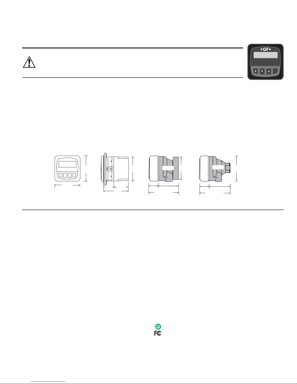
SIDE VIEW
Field Mount w/
8052 Integral kit
92 mm
(3.6 in.)
97 mm
(3.8 in.)
56 mm
(2.2 in.)
41 mm
(1.6 in.
)
Optional
Rear
Cover
Panel Mount
SIDE VIEW
FRONT VIEW
96 mm
(3.8 in.)
96 mm
(3.8 in.)
Field Mount &
Panel Mount
SIDE VIEW
Field Mount w/
8050 Universal base
106 mm (4.2 in.)
42 mm
(1.7 in.)
64 mm
(2.5 in.)
82 mm
(3.23 in.)
8050
96 mm
(3.8 in.)
107 mm (4.2 in.)
42 mm
(1.7 in.)
65 mm
(2.5 in.)
8052
Signet 8850-3 Conductivity/Resistivity Transmitter
2. Specifications
General
Compatible electrodes: Signet 3-28XX-1 Standard and Certified
Series Conductivity/Resistivity Electrodes
Accuracy: ±2% of reading
Enclosure:
• Rating: NEMA 4X/IP65 front
• Case: PBT
• Panel Case Gasket: Neoprene
• Window: Polyurethane coated polycarbonate
• Keypad: Sealed 4-key silicone rubber
• Weight: Approx. 325g (12 oz.)
Display:
• Alphanumeric 2 x 16 LCD
• Contrast: User selected, 5 levels
• Update rate: 1.8 seconds
Electrical
• Power: 12 to 24 VDC ±10%, regulated, 100 mA max.
Sensor input range:
• Conductivity: 0.01 μS/cm to 400 000 μS/cm
• Resistivity: 10 K•cm to 100 M•cm
• TDS: 0.023 to 200 000 PPM nominal (adjustable μS/PPM)
• Temperature: PT 1000, -25 °C to 120 °C (-13 °F to 248 °F)
Measurements above 10 M(below 0.1 μS) must be performed
in solution temperatures from 20 °C to 100 °C.
Two 4 to 20 mA Outputs:
• Passive, isolated, fully adjustable and reversible 4 to 20 mA
outputs are independently source selectable for conductivity or
temperature.
• Max Loop Impedance: 50 max. @ 12 V
325 max. @ 18 V
600 max. @ 24 V
• Update Rate: 200 ms
• Accuracy: ±0.03 mA @ 25°C, 24 V
Open-collector output, optically isolated:
• 50 mA max. sink, 30 VDC maximum pull-up voltage.
• Programmable for:
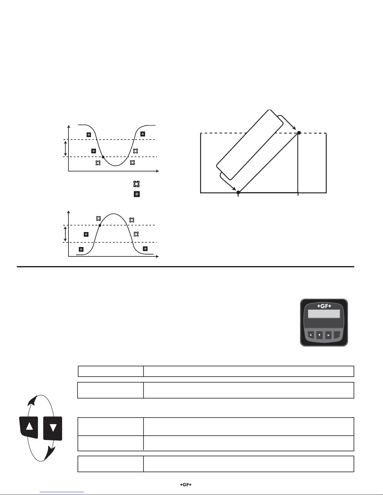
• High or Low with adjustable hysteresis
• Pulse operation (max rate: 400 pulses/min).
Environmental
Operating Temperature: -10 °C to 70 °C (14 °F to 158 °F)
Storage Tmperature: -15 °C to 80 °C (5 °F to 176 °F)
Relative Humidity: 0 to 95%, non-condensing
• Maximum Altitude: 2000 m (6562 ft)
• Insulation Category: II
• Pollution Degree: 2
Standards and Approvals
• CE, UL listed
• Manufactured under ISO 9001 for Quality, ISO 14001 for
Environmental Management and OHSAS 18001 for Occupational
Health and Safety.
China RoHS (Go to www.gfsignet.com for details)
Declaration of Conformity according to FCC Part 15
This device complies with Part 15 of the FCC rules. Operation is
subject to the following two conditions:
(1) This device may not cause harmful interference, and,
(2) This device must accept any interference received, including
interference that may cause undesired operation.
Signet
Conductivity/Resistivity
Transmitter
ENTER
62.50 uS/cm
25.0 C
CAUTION!
• Remove power to unit before wiring
input and output connections.
• Follow instructions carefully to avoid
personal injury.
Contents
1. Installation
2. Specifications
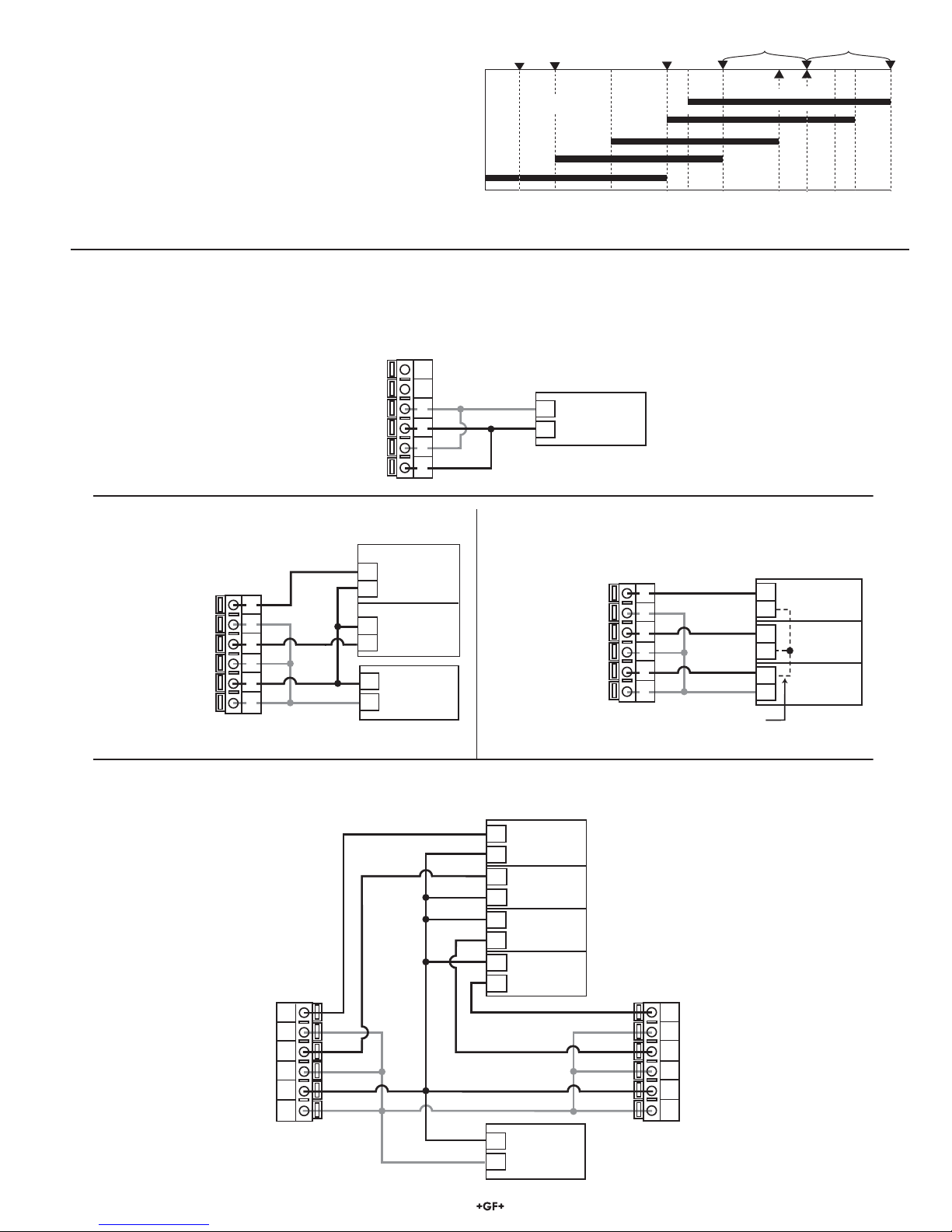
3. Electrical Connections
4. Menu Functions
1. Installation
ProcessPro transmitters are available in two styles: panel mount and field mount. The panel mount is supplied with the necessary
hardware to install the transmitter. This manual includes complete panel mounting instructions.
Field mounting requires a separate mounting kit. The 3-8050 Universal kit enables the transmitter to be installed virtually
anywhere. Detailed instructions for field installation options are included with the 3-8050 Universal kit.
1.1 Panel Installation
1. The panel mount transmitter is designed for installation using a 1/4 DIN Punch. For manual panel cutout, an adhesive
template is provided as an installation guide. Recommended clearance on all sides between instruments is 1 inch.
2. Place gasket on instrument, and install in panel.
3. Slide mounting bracket over back of instrument until quick-clips snap into latches on side of instrument.
4. To remove, secure instrument temporarily with tape from front or grip from rear of instrument. DO NOT RELEASE.
Press quick-clips outward and remove.
3-8850.090-3 Rev. K 11/12 English
*3-8850.090-3*
English