DOMUSA TEKNIK BioClass iC 66 User manual

FUEL SUCTION SYSTEM
ASH COMPRESSOR DRAWER
Bioclass iC 66 | Bioclass HC
EN | INSTALLATION AND OPERATING INSTRUTIONS


3
BIOCLASS iC 66 | HC
ÍNDICE
1 LIST OF COMPONENTS ............................................................................................................... 4
2 FUEL SUCTION SYSTEM INSTALLATION ...................................................................................... 5
2.1 INSTALLING THE FUEL SUCTION SYSTEM ........................................................................................................ 6
2.2 INSTALLING THE SUCTION HOSE ................................................................................................................... 9
2.3 INSTALLING THE AERATOR ACCESSORY ......................................................................................................... 11
2.4 START-UP ............................................................................................................................................ 12
3 FUEL SUCTION SYSTEM OPERATION ........................................................................................ 13
3.1 TIME PROGRAMMER FUNCTIONING .............................................................................................................. 14
3.2 FUNCTIONING WITH A TEXTILE SILO OR SUCTION NOOZLE ................................................................................. 15
3.3 FUNCTIONING WITH A KIT SPIDER .............................................................................................................. 16
4 MAINTENANCE ......................................................................................................................... 18
4.1 SAFETY WARNINGS ................................................................................................................................ 18
4.2 CLEANING THE PROTECTIVE GRILL ............................................................................................................... 19
5 MEASUREMENTS ...................................................................................................................... 20
6 TECHNICAL DATA .................................................................................................................... 21
7 ELECTRICAL DIAGRAMS ........................................................................................................... 22
7.1 ELECTRICAL DIAGRAM ............................................................................................................................. 2 2
7.2 ELECTRICAL CONNECTION FOR INSTALLATION WITH A DOMUSA TEKNIK TEXTILE SILO ........................................... 23
7.3 ELECTRICAL CONNECTION FOR INSTALLATION WITH A DOMUSA TEKNIK KIT SPIDER .............................................. 24
8 COMPRESSOR ASH DRAWER OPERATION.................................................................................. 25
8.1 EMPTYING AND CLEANING THE ASH DRAWER .................................................................................................. 25
8.2 SAFETY WARNINGS ................................................................................................................................. 26

EN
4
BIOCLASS iC 66 | HC
1 LIST OF COMPONENTS
1
2
4
3
1. Pellet hopper.
2. Fuel suction system.
3. BioClass iC / HC boiler.
4. Ash box.

5
BIOCLASS iC 66 | HC
2 FUEL SUCTION SYSTEM INSTALLATION
To guarantee optimum functioning of the Fuel Suction System and a long lifetime, the installation and
maintenance must be carried out by qualified personnel authorised by DOMUSA TEKNIK. The installer is
responsible for any devices or controls not supplied with the boiler.
This appliance must only be used for the purpose for which it has been expressly designed. Any other use
is considered unsuitable and therefore hazardous. The manufacturer shall not be considered liable under
any circumstances for damage caused by unsuitable, erroneous or irrational use.
The Fuel Suction System is specifically designed to convey 6 mm diameter pellets from a main silo to a
cyclone on a boiler reserve tank, providing it is installed together with a suction system (a DOMUSATEKNIK
KitSpider) or a DOMUSATEKNIK prefabricated textile silo including a pneumatic extraction device (cyclone)
or a DOMUSA TEKNIK suction nozzle kit for on-site tanks..
During installation or before any servicing, the following indications must be observed to prevent personal
injury or material damage:
Remove all the packaging and check the content is complete. In case of doubt, do not use
the Fuel Suction System. Contact your supplier. The packaging elements may be
dangerous so keep them out of reach of children.
Unplug the boiler from the mains before any servicing and during installation.
For safety reasons, another person should always be present when you access the pellet
store. If access to the store is difficult, we recommend a second person waits outside to
guarantee the safety of the person entering the store, to be able to let them out in case of
hazard without endangering their own life.
Before entering the pellet store, ensure it is correctly ventilated (there may be a lack of
oxygen or concentration of unknown gases).
Always wear a protective mask (standard mask) inside the pellet store for protection from
airborne dust.
Keep children away while you are working in the pellet store.
If the pellet store is flooded there is no risk of contamination of the groundwater, the soil
and/or the building, although the tank and pellet removal system could be damaged.
When it is decided not to use this Fuel Suction System, you MUST disable all parties may
constitute potential sources of danger.

EN
6
BIOCLASS iC 66 | HC
2.1 Installing the Fuel Suction System
Carefully follow these assembly instructions for correct assembly and installation of all the Fuel Suction
System components:
Cyclone
Before installing the cyclone on the reserve tank, adjust its counterweight so that the lower cover is
1,5 and 3 cm open. To do this, hang the cyclone vertically, loosen the butterfly nut fixing the
counterweight and move the counterweight so that the cover is open by this distance. After adjusting
the counterweight, remember to tighten the butterfly nut again, to prevent the counterweight
maladjustment during system functioning.
1,5 cm
Fixin
g
butterfly
Counterwei
g
ht
There is a ventilation slot on the rear of the tank to prevent a vacuum from being created inside it. Do
not cover this slot, and keep it free from any obstacles that could block it.
Do not cover

7
BIOCLASS iC 66 | HC
Filling sensor
As in the case of the cyclone counterweight, it is necessary to regulate the position of the filling sensor
relative to the fill indicator, so that there is a gap of between 2 and 3 mm. To achieve this, adjust the
nut and the locknut of the sensor to obtain the correct distance.
The filling sensor is regulated from the factory therefore is not necessary to adjust it unless the filling
sensor might have been maladjusted during the transport.
32- mm
Sensor de llenado
Indicador de llenado
FIll indicator
Fillin
g
senso
r
Connecting the suction hoses
The various Fuel suction system components must be connected pneumatically using a hose with an
interior diameter of 50 mm, preferably a flexible plastic hose with electrostatic charge accumulation
protection.
To ensure the system is correctly connected and sealed, the Fuel Suction System includes 4 cable
ties for fixing the hose ends to the respective pneumatic components of the kit.
The figure below shows the pneumatic connection of the different Fuel Suction System components.
B
Cyclone
A
B
T
extile
silo
A
Kit Spide
r
B
A
Suction
nozzle
A
B
A
Run a hose from the main storage silo (intake A) and connect it to the intake of the cyclone (intake
A).Run a hose from the air intake (intake B) on the rear of the cyclone and connect it to the intake B
of the textile silo or Suction nozzle.
If you are using a Kit Spider removal system, it is not essential to run the return hose to the silo, but
we recommend doing so to prevent the areas the hose opens onto from getting dirty.

EN
8
BIOCLASS iC 66 | HC
Electrical connection with the boiler
The CVS Suction System can be connected either with any of the BioCLass HC boilers.
The Fuel suction system is equipped with 2 cables, communication cable and power supply cable, which
are provided with pin terminal blocks in order to help their connection to the boiler ( and ).
Unroll the cables and lead them to the bottom of the electrical board of the boiler introducing them
through the back of the boiler
To correctly connect the Fuel Suction System to the boiler, first open the boiler door. The electrical
connection must be made at the lower part of the electrical board of the boiler. To access the lower
part of the electrical board, remove the cover from the connection strips (A), as described in
the figure. The communication cable must be connected to the J4 connector and
the power supply connector must be connected to J12, following the "
Electrical diagrams
" section
of this manual carefully.
A
Electrical board
J2 J3
J7
14 13 N 12 11 10 9N8
23 22 21 20 19 18 17 16 15
J6 J5
7NN6 543
J4
+A-B
J1
21
J12
21
Fuel suction system
power supply cable
Fuel suction system
communication cable
During installation or before any servicing, the following instructions must be observed:
Before carrying out any work on the boiler's electrical installation of the Fuel suction system,
always ensure the boiler is disconnected from the mains.
Make sure that none of the cables come into contact with a hot surface (e.g. fireplace or
smoke chamber).

9
BIOCLASS iC 66 | HC
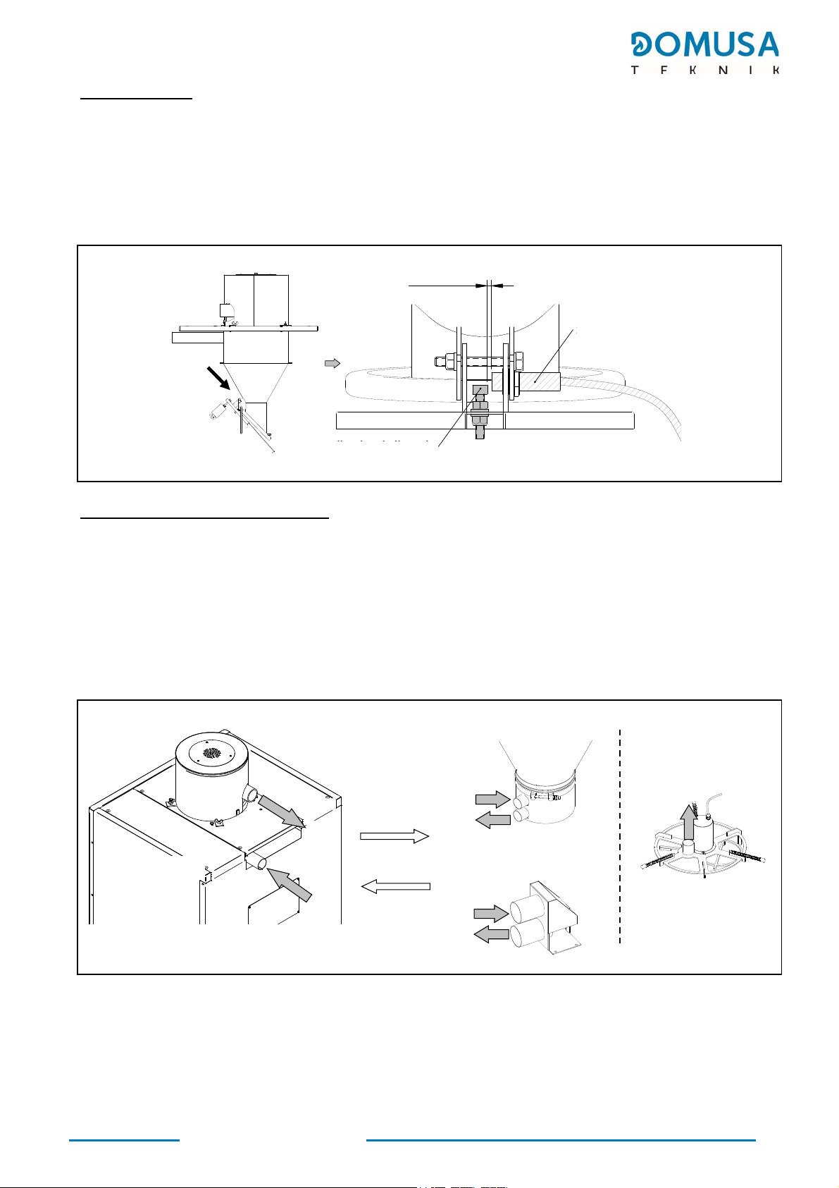
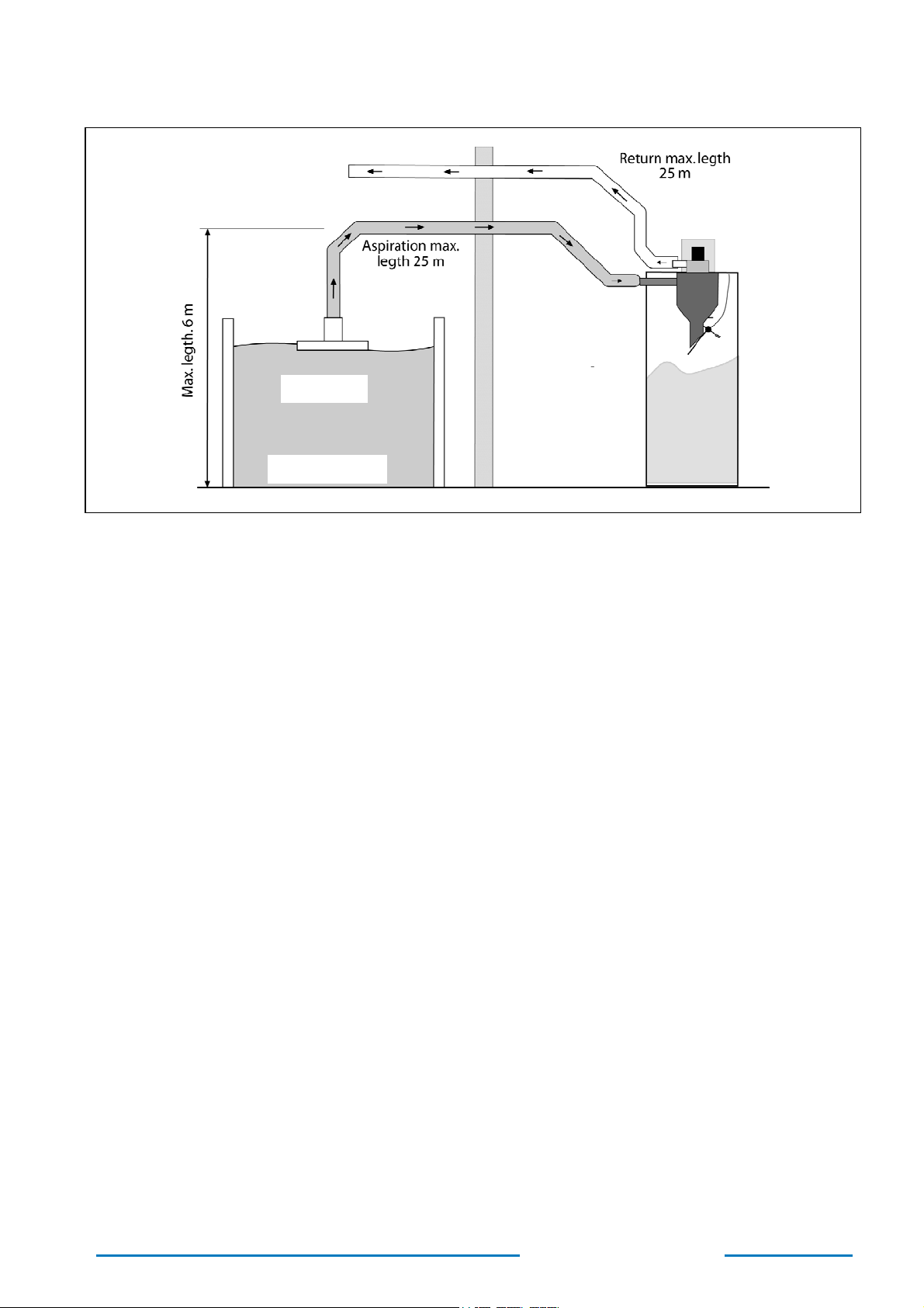
2.2 Installing the suction hose
The Fuel Suction System is specially designed to function as part of an installation with a plastic
hose with an interior diameter of 50 mm. This hose must have a static electricity discharge system,
preferably a copper wire wound around its entire length. This copper wire must be earthed at all the
hose joints and ends.
Whatever the type of hose used, it must be made of a suitable material for transporting wood pellets
and it must always have an interior diameter of 50 mm. The following recommendations must also be
complied with for correct installation:
The maximum permitted hose length is 30 metres for flow from the main silo to the cyclone
and 30 metres for return.
Bend angles of over 45º must be avoided whenever possible. If these cannot be avoided,
any curves with angles over 45º must have a radius of curvature greater than 125 mm.
If rigid plastic tubing is used, do not use standard 90º elbows. If these are necessary, the curves
constructed must have a minimum radius of 125 mm.
The flexible tube can be mounted in straight sections of a maximum of 4 meters.
Incorporating small bends reduces tube wear.
The maximum height difference permitted for the installation is 6 metres.
Avoid any splicing or coupling in the hose installation wherever possible, as this may narrow
the circuit, which can cause clogging of the pellets being transported and could block the
system. Most importantly, avoid any joints in the hose section leading from the main silo to
the boiler reserve tank cyclone, as the pellets are conveyed through this section.
If there is no alternative to splicing and extending the installation, straight rigid tubing with
an interior diameter of 50 mm must be used. It is preferable for any splicing and joining of
the hose to be done in the pneumatic suction system return section, as only air is conveyed
in this section. All the hose sections must be earthed at all coupling points and at the ends of
thehose.
The most vital factor for ensuring maximum suction power for the system is the airtightness
of the installation, and great care must therefore be taken when installing the tubing. All
coupling points in the installation must be secured with brackets, taking special care to
prevent leakage. We recommend avoiding hose crossover in the installation whenever
possible. The flow and return hoses of the pneumatic installation should be laid out parallel
to each other.
For correct assembly of the hoses, they should be fixed to the walls and/or floor using suitable
fasteners throughout the entire installation, to ensure stability. The recommended maximum
distance between the fixing points is 80 -110 cm.

EN
10
BIOCLASS iC 66 | HC
Some of these recommendations are illustrated in the figure below:
KIT SPIDER
MAIN SILO
RESERVE
TANK
IMPORTANT: At each end of the pellet suction and air return hose, the copper cables
must be connected to the earth connection terminals provided for this
purpose.
IMPORTANT: DOMUSA TEKNIK will hold no liability for malfunctioning of the Fuel Suction
System if the installation does not comply with the above recommendations.

11
BIOCLASS iC 66 | HC
2.3 Installing the aerator accessory
The aerator accessory supplied with the kit can be fitted in order to avoid blockages or clogging of the
pellet suction system. This aerator will ease the transport of fuel to the CVS, avoiding clogging and
blockages.
To install the aerator accessory, partially cut the suction pipe, 250 mm from the end closest to the storage
silo, without cutting the internal copper cable. Then fit the aerator accessory to the sectioned part, securing
it with two clamps.
To ensure the correct working of the suction system, cover or clear the slots of the aerator until optimal
extraction is achieved
IMPORTANT: It is essential to ensure that both sections of the suction pipe are earthed

EN
12
BIOCLASS iC 66 | HC
2.4 Start-up
In order for the guarantee to be valid, the Fuel suction system must be started up by personnel
authorisedby DOMUSATEKNIK. Before beginning the start-up process, the following must be complied
with:
The Fuel Suction System must be connected to the electrical mains power.
The main storage silo must be filled with pellets.
The pneumatic hose installation must have been carried out.
The start-up sequence is as follows:
Check the pneumatic installation of the 50 mm interior diameter hose has been performed
correctly.
Check the correct type of fuel is being used (EN 14961-2 class A1 grade or higher).
Check the Fuel suction system is working correctly.

13
BIOCLASS iC 66 | HC
3 FUEL SUCTION SYSTEM OPERATION
The Fuel Suction System is an automatic pellet conveying and suction system equipped with an
electronic control that governs the functioning of a suction device (suction turbine), by controlling the
signal from a sensor which detects the fill level of the tank, located in the cyclone of the reserve tank.
Furthermore, a programmable timer can be accessed via the display on the boiler so that the operation
may be disabled at night to avoid any noise and disturbance which may be caused by the suction system
during its operation. It can also manage the functioning cycles of a DOMUSA TEKNIK Spider Kit, if you
choose to use this type of pellet removal system.
The operation is as follows: when the filling sensor detects a low pellet level, the electronic control starts
up the suction unit, which begins to suck the pellets from the silo or main store and convey them to the
cyclonic tank at the top of the boiler reserve tank. The suction turbine runs for a set duration (a cycle),
while it fills the cyclonic tank. When the cycle is complete, the suction unit stops and the hatch on the
underside of the cyclone opens, emptying the pellets inside it into the reserve tank. If the filling sensor
continues to detect no pellets when the cyclonic tank has been emptied, the suction unit starts up again
and runs for another full cycle. When the sensor detects the filling of the reserve tank (cyclone door open),
the control disables the Fuel suction system and waits until it is reactivated.
During the time that the suction unit runs, the symbol is displayed blinking in the boiler‘s display.
If the filling sensor doesn’t detect pellets after 9 consecutive cycles, the electronic control stops the system
functioning and the alarm E-27 is activated (Fuel suction system lock out), in the display of the boiler. To
unlock it, press and 9 more consecutive cycles or until the sensor detects the filling of the tank,
as long as the time programming of the charging system allows it.
The cycle time could be adjusted using the P.22 setting of the “Technical” menu (see instructions of the
boiler). This setting is used to optimise the filling time for the cyclone of the tank, adapting it to the
different characteristics of each pneumatic installation (suction length, type of pellet removal system, etc.).
The adjustable time range is from 35-195 seconds per cycle. Guidance regarding the recommended cycle
times for different types of installations is given in the following sections.

EN
14
BIOCLASS iC 66 | HC
3.1 Time programmer functioning
The electronic control of the Fuel Suction System allows access, via the boiler control cover, to a
programmable timer in order to disable its functioning at night, to prevent noise from the suction
system.
The pellet reserve tank has a 60 Kg capacity. For correct operation please note that the consumption
of the boiler during the deactivated period of the CVSSuctionSystem must not exceed the range of the
hopper.
To program the system ON and OFF periods, proceed as follows:
Once you access to the “Configuration” menu of the boiler, by default the timer will be
annulled and the display will be shown as in the figure. Press , the symbol SET blinks,
and the adjustment of the timer starts.
At the top of the display is shown the time zone, from 0 to 24 hours. Press + / -
repeatedly to progress sequentially through the hours every 30 minutes to choose the desired
time period.
At each time period pressing + / - the condition of the timer is adjusted. If appears the
symbol " ", the Fuel suction system stays “Off” and if appears the symbol " " the Fuel
suction system stays “On”. The periods adjusted with " “symbol will be marked in the time
zone of the top of the display.
Press to record the last timer adjustments and it returns to "Configuration" menu.

15
BIOCLASS iC 66 | HC
3.2 Functioning with a Textile Silo or Suction noozle
In the case of an installation with a fabric silo or suction nozzle kit supplied by DOMUSA TEKNIK, the
suction turbine will be activated every time the cyclone sensor detects a lack of pellets and will remain
in operation during the cycle time set by the user in parameter P.22 of the “Technician” menu of the
boiler. When the sensor detects the filling of the tank, the control will deactivate the operation of the
suction turbine and will wait to be activated again. If after 9 consecutive cycles the sensor still does
not detect the filling of the tank, the control will block the operation of the system and the alarm E-27
(Blockage of the fuel suction system) will be activated on the boiler screen. To unblock the system,
press on the boiler control holder and 9 more consecutive cycles will be run again or until the
sensor detects the tank filling, as long as the time programming of the charging system allows it.
The optimum cycle time is the time required for the cyclone on the reserve tank to fill up to full capacity.
The amount of pellets conveyed per cycle will depend on the length and route of the installation and
the type of pellets used. Bearing in mind these variable fuel characteristics, the table below shows some
recommended cycle times, depending on the length of the installation.
Installation length Cucle time
5 m MIN (35 sec)
15 m 60 sec
30 m 120 sec
The figure below shows a functional diagram of the Fuelsuctionsystem installed in combination with a
DOMUSA TEKNIK textile silo:
NOTE: If the suction system becomes blocked, this could mean there are not enough
pellets in the main silo or that the pneumatic hose installation has become blocked
or is defective.

EN
16
BIOCLASS iC 66 | HC
3.3 Functioning with a Kit Spider
If the installation is made in combination with the KitSpider pellet removal system of DOMUSA TEKNIK,
whenever the tank filling sensor detects that the pellet level is low, the electronic control will begin
each cycle by starting up the suction unit and KitSpidermotor at the same time, turning the kit’s rotary
plate and sucking up pellets from the main silo. When the cycle is complete, in order to prevent excess
pellets remaining in the hose installation and causing obstruction at the start of the next cycle, the
control stops the Spider Kit functioning 15 seconds before suction unit operation is disabled. This means
the suction unit continues taking in only the pellets that remain in the hose installation, emptying the
hose and preventing obstruction when the next cycle begins.
If the filling sensor doesn’t detect pellets after 9 consecutive cycles, the electronic control stops the
system functioning and the alarm E-27 is activated (Fuel suction system lock out), in the display of the
boiler. To unlock it, press and 9 consecutive cycles will start again unless the sensor detects
pellets.
In general, we recommend adjusting the cycle time to its maximum setting (195 seconds), by turning
the adjustment screw clockwise as far as it will go. If the installation settings are causing the boiler
reserve tank cyclone to fill up some time before the end of each cycle, we recommend reducing the
cycle time for closer adjustment, so that it coincides with each filling of the cyclone. It should also be
observed that the amount of pellets taken in on each cycle may vary considerably depending on suction
unit filter maintenance, pellet quality and the main silo emptying level at any given time, and it is
therefore preferable to set long cycle times.
The figure below shows a functional diagram of the Kit Spider installed in combination with a Fuel
Suction System:

17
BIOCLASS iC 66 | HC
The rotary plate of the Kit Spider moves in circular fashion in symmetrical rotation cycles, alternating
between clockwise and counter-clockwise movement to prevent the hose from winding onto the kit.
These rotation cycles are governed by the boilers electronic control system. The diagram below shows
the functioning cycles controlled by the boiler:
NOTE: If the suction system becomes blocked, this could mean there are insufficient
pellets in the main silo or that the pneumatic hose installation has become blocked
or is defective.

EN
18
BIOCLASS iC 66 | HC
4 MAINTENANCE
To keep the Fuel suction system in perfect working order the maintenance operations described in this
section must be carried out at regular intervals.
Also, to ensure correct functioning of the boiler we recommend inspection of the whole pellet loading
system once a year by the DOMUSA TEKNIK Authorised Technical Service, at the same time as the annual
service.
Maintenance of the Fuel suction system mainly consists of emptying the dust accumulated in the
protective grille below the suction turbine.
4.1 Safety Warnings
To prevent any damage or injury to people and property, the following safety indications must be taken
into account during the maintenance operations described in the following sections:
Unplug the Fuel Suction System from the mains power before any servicing.
Wear a protective mask (standard mask) on cleaning the suction unit, for protection from
airborne dust.
Keep children away from the installation on carrying out the Fuel suction system maintenance
operations.

19
BIOCLASS iC 66 | HC
4.2 Cleaning the protective grill
Before cleaning the protective grille of the cyclone be sure to disconnect the Fuel suction system
from the mains.
At least once a year (depending on the amount of dust that the pellets contain), unscrew the cyclone
cover and vacuum the dust from the protection grid located below the suction turbine.
If the pellet suction turbine creates a lot of noise or sends off sparks, this could be due to dirt on the
fan blades. You must remove the suction turbine and clean it using a compressed air or vacuum cleaner.
The motor of the suction turbine has carbon brushes. Replace the brushes when the consumption
reaches approximately 55 tones of pellet.

EN
20
BIOCLASS iC 66 | HC
5 MEASUREMENTS
75
SA
EP
51.5
SA: Air suction, Ø50 mm.
EP: Pellet inlet, Ø50 mm.
Other manuals for BioClass iC 66
1
This manual suits for next models
1
Table of contents
Popular Air Compressor manuals by other brands

Sullair
Sullair 125 Operator's manual

Ingersoll-Rand
Ingersoll-Rand CSA XHP900WCAT operating & maintenance manual

Emerson
Emerson Copeland YB56K1G Application guidelines

Workzone
Workzone WZK 182 user guide

Panasonic
Panasonic SCROLL C-SB Series Applications manual

Craftsman
Craftsman 919.195410 owner's manual