DONG IL TECHNOLOGY LTD AMF-AE1 User manual

Instruction Manual
Read this instruction manual before using the product in order to achieve maximum performance.
Keep this instruction manual within your reach after reading so that it can be used at any time.
ION BLOWER AMF-AE Series
28, Namyang-ro 930beon-gil, Hwaseong-si, Gyeonggi-do, Korea
Tel 82.31.299.5453 Fax 82.31.357.2610

1. Product Introduction……………………………………………………………03Page
1.1 Features 1.2 Specification
1.3 Dimensions 1.4 Performance
1.5 Package contents 1.6 Parts’ names and functions
2. Installation……...………..……………………………………………..................09Page
2.1 Installation 2.2 Wiring diagram
2.3 Cautions
3. Cautions & Maintenance………….………………………….….…………..12Page
3.1 Cautions for operation 3.2 Cleaning & replacement of ion emitters
4. Settings……………….………………………………………………………………..15Page
4.1 How to set values 4.2 Explanation on Menu options
APPENDIX ……………………………………………………………….………………17Page
1. Trouble shooting
2. Warranty
Before installation, be sure to read carefully at least
1.7 Cautions
2. Installation & Connection parts
2
DONG IL TECHNOLOGY LTD
CONTENTS

1.1 Features
3
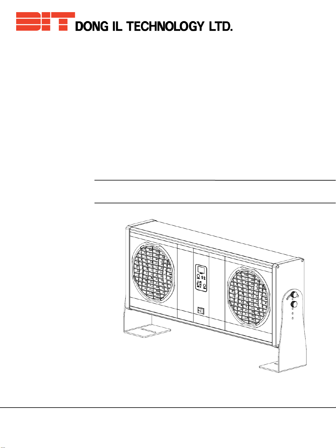
1. 제품 소개 DONG IL TECHNOLOGY LTD
Welcome to become a DIT customer!
AMF-AE series is a pulsed AC ion blower neutralizing static electricity using Corona
Discharge method.
AMF-AE series,
• is easy to maintain with auto cleaning function for emitter pin.
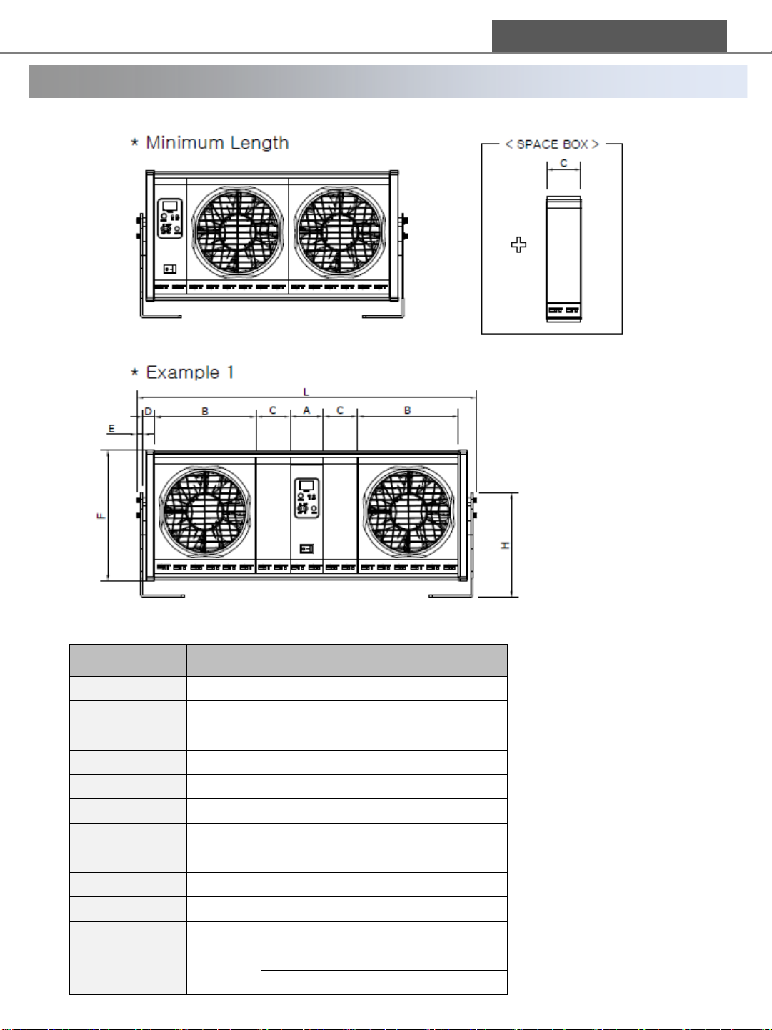
• has flexible assembly configuration according to customer’s needs combining up to
3 fan modules and needed number of space boxes.
• can be adjusted air volume up to 5-levels
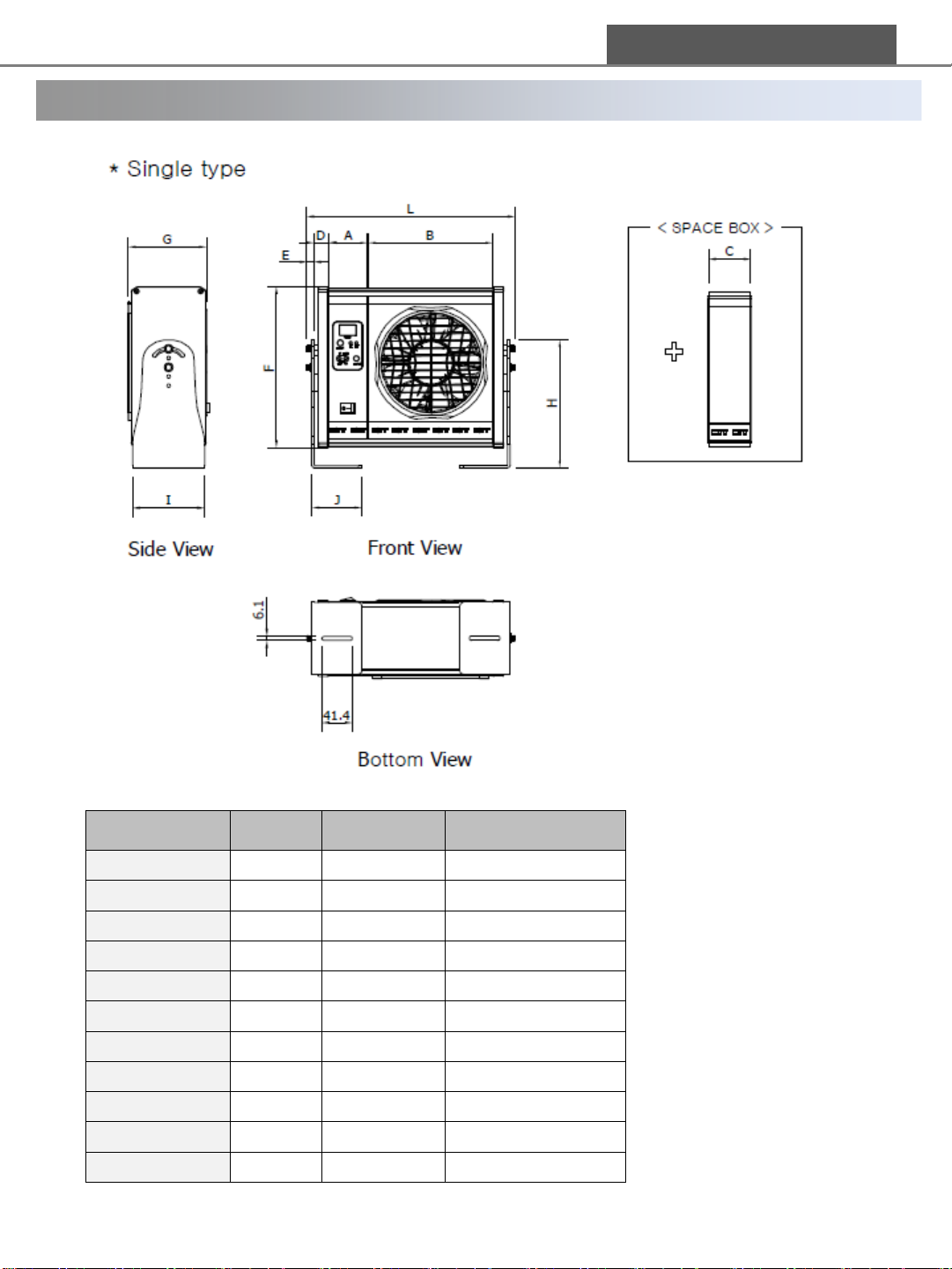
Category 1 –Fan 2 - Fan 3 - Fan
Input voltage AC100~240V(50/60Hz) or DC 24V±10%
Input current(AC) Max 0.61A Max 1.22A Max 1.83A
Input current(DC) Max 1.5A X X
Ion generating method Pulsed AC
Output Frequency 10Hz ~ 50Hz(adjustable)
Ion emitter pin Tungsten
Ion balance < ±30V Typical
Decay time Better than 2.0 seconds at 600mm [Fan Speed Max(Level 5)]
Air volume Max 6.4㎥/min per Fan
Ozone generation Under 0.005ppm
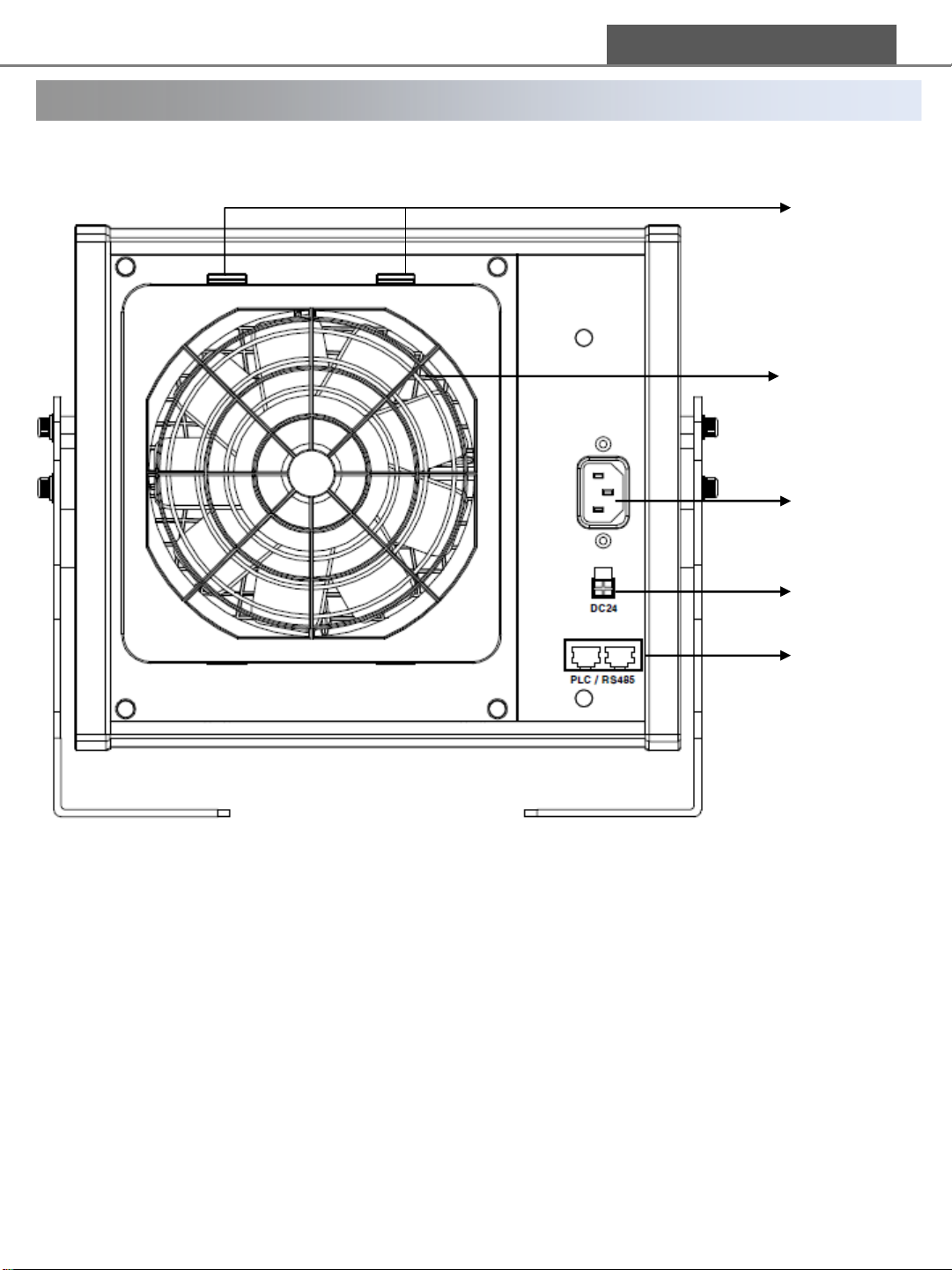
Display 7segment-Display ,High Voltage Alarm LED(G/R), Fan Alarm LED(G/R)
※ Green : Normal, Red : Abnormal
Manual control Fan Speed, Operating frequency, Ion-balance, Auto-cleaning,
PLC Alarm Select, Address, Ionizer On/Off, Password
Weight Max 7kg
Ambient temperature 0℃~50℃
Relative humidity 35~65%RH(No Condensation)
1.2 Specification
※ Specification can be changed without notice for performance improvement

4
DONG IL TECHNOLOGY LTD
1.3 Dimensions
Category Code Length [mm] Remarks
Controller A 54.6
Fan Module B 170.0
Space Box C 56.6
Side Cover D 18.6
Bracket Ass'y E 9.6
Height F 217.8
Width G 106.1
Bracket Height H 173.6
Bracket Width I 97.5
Bracket Depth J 68.0
Blower Length L 262 Min. Length

5
DONG IL TECHNOLOGY LTD
1.3 Dimensions
Category Code Length [mm] Remarks
Controller A 54.6
Fan Module B 170.0
Space Box C 56.6
Side Cover D 18.6
Bracket Ass'y E 9.6
Height F 217.8
Width G 106.1
Bracket Height H 173.6
Bracket Width I 97.5
Bracket Depth J 68.0
Blower Length L
432 Min. Length (2Fans)
602 Min. Length (3Fans)
1,000 Max. Length

6
DONG IL TECHNOLOGY LTD
1.4 Performance
. Relation between Distance and Decay Time
.Fan Speed: L 5
.Frequency : 30Hz
.Measure Condition: 1kV →100V
.Charged plate size : 150 x 150㎜
.Charged plate Capacitance : 20㎊
.Ambient conditions : 25℃, 45%RH

7
DONG IL TECHNOLOGY LTD
②Standard Bracket
1.5 Package contents
Be sure to check the package contents before installation.
①Main body ②Standard brackets ③AC power cable [1,800㎜]
④DC Power Cable 1500mm (Including ground wire)
⑤Remote controller ⑥RJ45 CABLE (8Pin) [PLC/RS485 Communications]
※ Options ※ Options
①Main body (ex. 1–Fan & 2–Fan)
④DC Power Cable (including
ground wire)
③AC Power Cable
⑥RJ45 CABLE (8Pin)
[PLC/RS485 Communications]
⑤Remote controller
*options*options

8
DONG IL TECHNOLOGY LTD
1.6 Parts’ names and functions
<Front-side>
①Control
- Display operation condition, menu and setting value
- Control on/off AC input power
②Air outlet and front cover
③Emitter fixing cover
④Ion emitter
⑤Bracket fixing wrench bolt (M5)
⑥Bracket
①②
③
⑥
⑤
④

9
DONG IL TECHNOLOGY LTD
1.6 Parts’ names and functions
LAMP
Red Green
Check
HV NG Good Ion Emission
<Controller>
<Display and control function>
①DISPLAY
Display operation condition, menu
and setting value
②Remote Control receiver
③Output power alarm (LED Green/Red)
Shows the state of ion emissions
④Fan malfunction alarm (LED Green/Red )
Shows whether fans are functioning
properly or not
⑤Menu operation keys
⑥Auto pin cleaning key
⑦AC input power on/off key
LAMP
Red Green
Check
FAN NG Good Fan Status
<Product condition and check point regarding LED>
①
②
③
⑥
⑤
⑦
④

10
DONG IL TECHNOLOGY LTD
1.6 Parts’ names and functions
<Back-side>
①AC POWER Connector
②DC POWER Connector (Only for AMF-AE1 Model)
- Be sure to check a diagram(page 13.) before wiring.
③RJ 45 Connector
- PLC cable, RS485 communication
④Filter Cover Lock
⑤Air inlet
①
②
③
⑤
④

11
DONG IL TECHNOLOGY LTD
1.6 Parts’ names and functions
<Bracket>
①Tilt hole
- Use this hole if you need to adjust angle.
②Height hole
- Use this hole if you need to adjust height.
③Main body fixing hole
- Fix a main body to installation place before operation.
①
②
③

12
DONG IL TECHNOLOGY LTD
2.1 Installation
①Install this blower making sure no obstruction between the blower and
the target object.
Separate air outlet part and target object, air inlet part and any object such
as wall minimum 150mm to keep air flow smoothly.
If you use more than 2 ionizers, keep a distance minimum 200mm from each
ionizer. If not, ionizers may no longer work ordinarily.
②Fix strongly a main body to installation place with provided brackets.
③AC Power cable must be plugged into a socket with proper ground
connection.
In case of no ground connection in a socket, connect ground cable using a
provided DC24V power cable. No grounding may cause a malfunction.
④In case of using DC power supply, be sure to connect the ground wire in
DC24V cable included in the package referring the wiring diagram 2.2.
The product must be connected to prevent electric shock and
guarantee best performance.
⑤When power is supplied, LED is lit on in red and, is turn into green within
a second. From then, ions are released to neutralizing static electricity.
⑥Control suitably fan speed to a install place.
Fan speed is quicken slowly because a motor spend a lot of electric power.
If you need to control fan speed, set a value on menu after fan speed is fast
enough.
⑦Check ion balance within ±30V, if not, adjust ion balance referring 4.1~4.2.
Warning
Warning
Warning
Warning
Warning

1313
PIN No.
Color Connection & Usage
①Black Communication TX(+) Signal RS485
Communication
②Brown PLC Circuit HVPS Alarm Signal
PLC
③Red PLC Circuit Ground
④Orange
NC
⑤Yellow PLC Circuit Clean Signal
⑥Green PLC Circuit On/Off Signal
⑦Blue PLC Circuit Fan Alarm Signal
⑧Violet Communication TX(-) Signal RS485
Communication
< RJ45 Cable Wiring>
DONG IL TECHNOLOGY LTD
2.2 Wiring diagram
PIN No.
Color Connection & Usage
①Black Power Ground (DC Power Ground)
②White Power Ground (DC Power Ground)
③Yellow +24V DC Power Supply
④Red +24V DC Power Supply
⑤Black Ground (Field Ground)
< 24V DC Power Input Cable >
24V DC power input cable wiring
1) Connect Black(short) wire & White wire to power ground and Black(long) wire to field ground.
2) Connect Red wire and Yellow wire to DC + 24V.
①
②
③
④
⑤
⑥
⑦
⑧

14
<AMF-AE Series PLC(NPN Type) Circuit Diagram>
2.2 Wiring diagram
Connection when using PLC
①Connect the red cable to a power and field ground.
②Connect the orange cable to PLC 24V.
③Connect the yellow(emitter cleaning) and green(PLC on/off) cables to PLC 0V,
which makes PLC work. If you open it, PLC doesn’t work
(Please refer to the AMF-AE Series PLC Circuit Diagram above.)
④The brown(HVPS) and blue(Fan) cables are for an alarm signal.
Setting Load: Set the output current under 100mA
DONG IL TECHNOLOGY LTD
PLC On/off S/W
1 2
7. Blue: Fan Alarm Signal
6. Green: PLC On/off Signal
LOAD
PLC CLEAN S/W
4. Orange: PLC P
상
(DC +24V)
5. Yellow: PLC Clean Signal
2. Brown: HVPS Alarm Signal
3. Red: PLC N
상
(GND)
DC 24V INPUT
LOAD
Warning

15
<AMF-AE Series PLC(NPN Type) I/O Table>
2.2 Wiring diagram
You should use lock type switch when you use a PLC On/off function.
You can only control PLC when a switch is closed.
You should use non-lock type switch when you use a PCL Clean function.
Auto pin cleaning function is operated repeatedly while switch is closed.
While PLC Clean Switch on a diagram is closed, ions are not generated
for safety reasons.
R, C filter on input terminal is connected in parallel to prevent malfunction
due to external environment or chattering noise. Keep close more than 0.5
seconds the switch when you use non-lock type switch.
DONG IL TECHNOLOGY LTD
Switch Display PLC Alarm ‘nc’
PLC Alarm ‘no’
Ion ‘on’
Close
I_o
Low High
Open
Ion ‘off’
Close P_o
Open I_f
High Low
HVPS error
/ Fan error
Er2
/Er4
PLC cleaning signal input
Switch Close CLn No PLC alarm output
Warning

16
DONG IL TECHNOLOGY LTD
2.3 Cautions
2.4 제품 설치 후확인 사항
①Supply power only after you make sure that the power cable is wired correctly according
to the wiring diagram in page 11.
②Ground installed equipment and ionizer. No grounding may cause malfunction.
Bracket fixing screw parts on left & right side is not for grounding. Connect AC or DC
power cable to ground.
③Excessive or insufficient power supply may cause the product’s disorder or malfunction.
④Use only authentic parts supplied. Using improper parts may cause malfunction.
⑤Be well informed of this instruction before installing or using the product.
⑥Don’t put extraneous materials like metal, wire, etc. near the product for safety.
⑦Don’t move, clean or touch the product during operation.
⑧Remove water and oil from the place where the product is installed and avoid high
temperature(50℃) and high humidity(RH 70%).
⑨Don’t use this product in the place influenced by strong magnetic field. It may cause
the product’s malfunction.
⑩Don’t use this product in the place where there is volatile material or a lot of dust.
There is risk of explosion.
⑪Wire all of cables when you supply DC 24V.
⑫The switch on front side is to supply AC power. Use DC power supply to control on/off
when you use DC24V.
Power software doesn’t work on DC 24V.
Warning

17
DONG IL TECHNOLOGY LTD
3.1 Cautions for operation
①Before connect the power cable, be sure to check the power supply specification and
wiring diagram.
②Don’t touch the product with a hand or other material during operation because high
voltage is generated.
③Don’t use chemicals or detergent for cleaning the product.
④Don’t use this product for any other purpose except for neutralizing static electricity
⑤Keep distance from the product during operation and don’t breathe for a long time
in front of air flow from the product
⑥Firmly fix the main body not to fall.
⑦Install the product beyond children’s reach.
⑧Don’t install the product in the place exposed to flame, direct ray of the sun or a lot
of dusts.
⑨Be sure to check a ground on ionizer and equipment before operation and
maintenance.
⑩Use a soft cleaning product when you remove dust on a front cover.

18
DONG IL TECHNOLOGY LTD
3.2 Cleaning & replacement of ion emitters
※ Please clean ion emitter pins regularly to guarantee the best performance of the
product. (Cleaning period can be different according to the usage circumstances.)
Auto pin cleaning function operation method
①Using the button on a front side.
- When PIN CLN key on a controller be pressed , auto pin
cleaning function is started.
②Using the timer on menu.
-Set a value which cycle you want on menu ‘tiP’.
- Refer to a detailed setting method on page 4.1.~4.2.
③Using the PLC.
After wiring, Refer to a diagram on page 3.2.
- While PLC Clean Switch on a diagram is closed, ions are not generated
for safety reasons.
PUSH
Warning

19
DONG IL TECHNOLOGY LTD
3.2 Cleaning & replacement of ion emitters
※ Please clean ion emitter pins regularly to guarantee the best performance of the
product. (Cleaning period can be different according to the usage circumstances.)
Manual cleaning method of pin and cover
①Be sure to disconnect power before cleaning or replacement of ion emitters.
②Separate the fan cover.
Fan cover is designed to be grabbed easily by a right hand. Grab the fan
cover, turn it counter clockwise a little bit and pull it toward the body .
③Cleaning:
Clean the ion emitters with cotton swab with alcohol and assemble it in
reverse order. Be cautious not to touch the emitter pin with a finger to
prevent finger prints. For cleaning a fan cover, use soft clothes or
tissues.
Handle emitter pins with care not to be hurt by the sharp point.
Replace emitter pins if emitter pins are damaged.
④Assemble it in reverse order.
How to replace emitter pin
Do step ①~②in manual cleaning method.
④Grab the emitter pin cover(②), turn it counter clockwise a little bit and pull
it toward the body, and then replace pin Assembly(①).
Be sure to assemble that the word ‘Front’ on cover is on a front side.
⑤Assemble it in reverse order.
.
No. Description
①Emitter pin Assembly
②Emitter pin cover
③Fan cover
Warning
Warning

4. 1 How to set values
20
When using key panel When using remote controller
Entering Menu
mode and
finding an option
Entering a
specific menu
option
(Ex: Address
setting)
Setting and
saving a value
Switching digits
Returning to
initial Menu
mode
Entering
address with
number key
Press “Menu” key: “MnU” is displayed
on the panel. Press OK to enter the
main Menu.
Use UP DOWN keys to find a specific
menu option that you need.
2 Seconds
Hold “OK” for 2 seconds when the
panel displays “Adr”. You can see the
previous setting value on display.
Use “UP”, “DOWN” keys to change the
value and press “OK” for 2 seconds to
save the changed value.
,Press “OK” while holding
“Menu” to be down digit.
Press “Menu” while
holding “OK” to be up
digit .
Entering right address display “SEL”
on FND. Pressing “OK” display “MnU”
on FND. Press OK one more time to
enter the main Menu.
Use “▲” or“▼” to find a specific menu
option that you need.
or
Hold “OK” for 2 seconds when the
panel displays “Adr”. You can see the
previous setting value on display.
Use “▲” or“▼” to change the value and
press “OK” for 2 seconds to save the
changed value.
or
Press“◀” or ”▶” to move
to next digit. Check you
have FND blinking.
Use“▲” or“▼” to make
changes.
or
Press “MENU” for more
than 2 seconds to return
to initial Menu mode.
Press “MENU” one more
time to return to a standby
mode.
Press “ESC” to return to
initial Menu mode.
Press “ESC” one more
time to return to a standby
mode.
DONG IL TECHNOLOGY LTD
and
1) Remote controller is optional.
2 Seconds
2 Seconds
This manual suits for next models
1
Table of contents
Other DONG IL TECHNOLOGY LTD Blower manuals