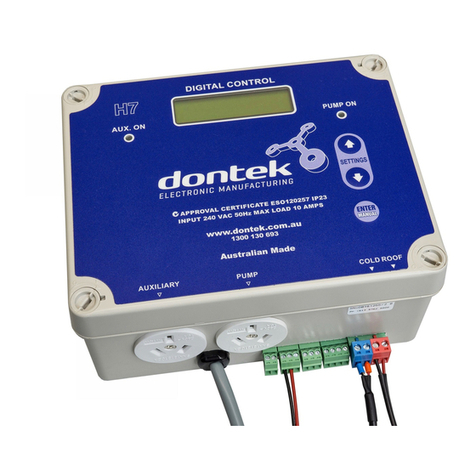
Dontek SLH7 SV User manual

SLH7 SV – INSTRUCTIONS
Page 1 of 4
CONTROLLER MOUNTING:
The controller enclosure must e firmly attached to a near y solid fixture y either the two mounting lugs or direct
attachment though the controller. If mounting through the controller ensure the power cord is disconnected from the
mains supply then remove the enclosure front cover y turning the four corner locks so each arrow points to the ‘O’
marked on the front cover. Insert two mounting screws diagonally through the oval holes in the enclosure, refit front
cover and turn the four corner locks to the ‘I’ position.
The power ca le is 1.8m long and should e plugged directly into a general power outlet, not into an extension lead.
CIRCULATING PUMP:
The circulating pump plugs into the right hand 240Vac socket marked as PUMP and will e operating as indicated y
the PUMP ON LED. The left hand 240Vac socket marked as Auxiliary provides continuous power as indicated y the AUX
ON. LED. The maximum allowable combined current for both sockets is 10 AMPS @ 2400W
HEATER INTERLOCK:
The heater interlock ca le connects to the green socket marked RELAY1 which switches on the NO/C contacts when the
heater is to e turned on. The other end of the heater interlock ca le connects in series (daisy chain) to the heater’s
flow or pressure switch circuit (refer manufactures instructions). If the heater’s flow/pressure switch circuit is 240Vac
then DO NOT connect the RELAY1 ca le directly to the heater, a KIT02 needs to e used which is supplied with an
external 240V rated relay which will need to e connected in series with the flow/pressure switch y a licensed
elect ician. Set the temperature setting on the heater 5°C a ove the desired water temperature to allow the SLH7 to
e in control without conflict.
VALVE:
The valve actuator is connected to the green socket marked VALVE, wired as descri ed on the la el. The valve is used
for selecting or ypassing the solar collector. Wire as per the la el on the controller.
TEMPERATURE SENSORS:
The pool sensor must e fitted into the suction line of the pump, prefera ly in a position out of direct sunlight. It is
recommended that a 14.5mm hole e drilled in the PVC pipe, this can e carried out using a Dontek PD01 grinding drill
or a small pilot hole can e drilled and a 14.0mm drill- it used spinning in a counter clockwise direction to minimize the
chance of shattering pipe. Insert the grommet into the pipe and gently push in the lack sensor ar . The green sensor
plug is to e fitted to the plug socket marked POOL.
Roof sensor must e fitted into a small piece of ru er collector material away from the main collector ut on the same
aspect. Keep in mind that it is of the utmost importance to keep the roof sensor ca le as short as possi le as this will
assist in the longevity of the sensor and controller in the event of electrical storm activity and power surges. Sensor
ca les must not be run parallel to power cables and run lengths should e less than 50m. Ca le ties should e used to
fasten the sensor ca le to the cold water inlet pipe making sure that the ties are approximately 10mm from PVC
fittings. Ca le ties should e tightened only firm, over tightening can cause reaks in the outer PVC if not careful. If the
ca le is to e run under ground a conduit must e used to protect the wire and there is to e no ca le joins within,
conduit ends must e sealed to prevent water ingress Any excess cable should be removed and re-fitted ensuring that
the wire ends are tinned with solder The sensor plug is to e fitted to the right hand socket marked ROOF.
DESCRIPTION:
The SLH7 SV is a swimming pool controller that heats a swimming pool y the use of an auxiliary heater or if solar gain
is availa le an automatic valve will divert water to the solar collectors.
The auxiliary heater (gas or heat pump) has a temperature limit setting (AUX LIMIT) and run time settings, the pool
will e heated to this limit y the auxiliary heater, in situations of high solar gain the controller activates an energy
saver mode, in energy saving mode the auxiliary heater is switched off regardless of pool temperature when the roof
temperature exceeds 15°C a ove the AUX LIMIT, once the energy saver mode is active the auxiliary heater remains
OFF until the roof temperature drops elow the AUX LIMIT plus 10°C.
If solar gain is availa le the solar system will heat the pool to the solar limit (SOL LIMIT).
Solar has a time lockout that prevents heating outside the hours of 08:00 to 19:00 and can e changed (see note 6).
An automatic divert valve will divert water to the solar collectors when there is enough solar gain and will ypass the
collector when solar heating is no longer availa le.
Heating is performed to the temperature limit plus ½°C and once that temperature is achieved heating will no re-occur
until the temperature drops elow the desired limit y ½°C or until the sample period has elapsed and the temperature
is at or elow the limit.
SETTINGS MENU
All items on the LCD that flash are adjusta le items, use the Up or Down uttons to modify the adjusta le item. Press
Enter to accept the adjusta le value.
To enter the SETTINGS MENU push either the up or down uttons and the following will e displayed;
SETTINGS MENU
1) MANUAL MODE
All menu items are shown elow, use the Up or Down uttons to scroll to different items in the menu;
SETTINGS MENU
1) MANUAL MODE
2) TEMPERATURE
3) HEAT DEMAND
4) SOLAR MODE
5) SET CLOCK
6) SAVE & EXIT

SLH7 SV – INSTRUCTIONS
Page 2 of 4
1) MANUAL MODE
MANUAL MODE 24H
UP=ON DOWN=OFF
MANUAL MODE allows you to manually set the pump to ‘on’ y pressing the Up utton or ‘off’ y pressing the Down
utton.
Pressing Enter will return you to the SETTINGS MENU. You can also keep pressing Enter to toggle the pump from ‘on’
to ‘off’ and vice versa.
MANUAL MODE will time out, after 24 hours the SLH7 will return to automatic operation.
2) TEMPERATURE
TEMPERATURE
SOL LIMIT XX X°
When you enter the TEMPERATURE menu you may change the solar temperature limit setting y pressing the Up/Down
uttons, if no change is required simply push Enter and you will then e taken to the AUX LIMIT setting. (Factory
default is for SOL LIMIT is 30°C.)
TEMPERATURE
AUX LIMIT XX X°
Note: If heat demand is turned off, aux limit will not e shown.
You may change the auxiliary heater temperature limit setting y pressing the Up/Down uttons, if no change is
required simply push Enter (Factory default is for AUX LIMIT is 25°C.)
NOTE: For maximum efficiency it is advisa le that the solar limit (SOL LIMIT) e set higher than the auxiliary limit (AUX
LIMIT) SETTING THE AUX LIMIT HIGHER THAN SOLAR LIMIT WILL RESULT IN COOLING!
3) HEAT DEMAND (only set ON if auxilia y heating fitted)
HEAT DEMAND
ON/OFF
When you enter the AUX. HEATER menu you will need to select ON or OFF.
If OFF is selected you will return to the menu and the heater will never run automatically, If ON is selected you will e
prompted for START and END time, the heater will only run etween these times.
HEAT DEMAND TIME HEAT DEMAND TIME
START TIME hh:mm END TIME hh:mm
NOTE: if a 24 hour continuous run time is required then set the start time and end time to the same value. (E.g. Start
12:00, End 12:00)
IF LIMIT ACTIVE
SAMPLE AT XXXX
Sets the sampling period once the pool has reached the auxiliary or solar temperature limit, options are 15 min, 30
min, 1 hour, 2 hours. Once the pool reaches the aux or solar temperature limit the pump is turned off it will not e
turned on until the sample period expires*, the pump will then run for a minimum period of 3 mins so that water can
flow past the pool temperature sensor and o tain an accurate reading. Should heating e required the pump will
remain on to heat the pool.
*The sampling period may end if solar gain ecomes availa le, for this to occur the roof must e greater than 40°C
and the last pool temperature (when the pump was running) is under the solar limit.
GAS HEATER USED?
YES/NO
Setting this option to YES will turn off the heater efore the valve is moved to the roof, auxiliary heating will then
resume until solar gain is high or until aux limit is reached. For PARALLEL installation the heater remains off while water
is diverted to the solar collector (See HEATER CONFIG.)
HEATER CONFIG
PARALLEL WTH SOL/INLINE WTH SOLAR
This setting depends on the installation; if the valve diverts all water flow to the roof then select PARALLEL WTH SOL, if
the water return path from the solar collector returns to the heater then choose INLINE WTH SOLAR.
**Factory default for HEAT DEMAND is OFF (06:00 to 22:00, sample @ 1 hour) GAS HEATER = ON, HEATER SETUP =
PARALLEL WTH SOL

SLH7 SV – INSTRUCTIONS
Page 3 of 4
4) SOLAR MODE
MODE MODE MODE
SUMMER MODE AUTO WINTER MODE TROPICAL MODE
SUMMER MODE is the normal operation of heating the swimming pool.
TROPICAL MODE is selected if you wish to cool the swimming pool, the solar pump will run if the roof temperature is
colder than the pool until SOL LIMIT is o tained; note that this is most likely to occur at night.
WINTER MODE, when selected you will e prompted to select the start month of winter and the start month of
summer, the purpose of winter mode is not to use solar to heat the pool ut to ensure the solar collector on the roof
gets flushed otherwise the water in the collector ecomes contaminated. If AUX. HEATER is set to OFF a 3 minute flush
of the solar matting occurs etween 10:00 and 16:00 providing the roof temperature is equal or greater than the pool,
ut if that condition does not occur a solar system flush will e forced to occur at 16:00.
If AUX. HEATER is set to ON then the system operates similar to summer mode ut solar pump activity is monitored
and will force a 3 minute flush if solar has not een active for seven days, note the unit may flush if winter mode is
selected on the day of install.
**Factory default for solar mode is SUMMER MODE
5) SET CLOCK
When you enter the CLOCK menu you will e prompted to set the calendar & time.
Adjust values y pressing the Up/Down uttons, to accept the setting press the Enter utton, repeat until all values are
correct.
6) SAVE & EXIT
When this menu is selected, push Enter to save ALL settings, the unit will return to normal operation automatically.
Note: If any of the menu items are left unattended for 3-4 mins the menu will time out and automatically save all
settings and return to operation.
The ENTER/MANUAL button (Manual heating mode)
FOR MANUAL MODE
PRESS ENTER NOW
Pressing the Enter utton once will display the a ove message for ~3 seconds, to prevent accidental manual mode if
ENTER is not pressed again within the 3 second period then the controller will revert to automatic operation (and it will
cancel any pump lockout delays).
If ENTER is pressed again within 3 seconds then manual mode is activated, the solar pump is stopped (if operating)
and the aux pump (filtration) is switched on, the following is displayed;
MANUAL MODE 4HR
23 5° SET=30 0°
The displayed temperature on the left hand side is the water temperature; the SET temperature displayed on the right
hand side is what manual mode will heat the water to efore the aux. heater is switched off.
Use Up utton or Down utton to change the SET temperature to the required comfort level.
Press & hold ENTER/MANUAL to exit manual heating mode and revert ack to automatic mode.
Manual heating mode will automatically revert to automatic operation 4 hours after the last temperature adjustment.
NOTES.
1. If a sensor fault is detected the SLH7 will display which sensor and what the fault is.
2. Should power e interrupted for any reason, the SLH7 will resume normal operation when power is restored,
all information will have een kept.
3. Temperature sensors used with this unit are Digital and are accurate to 0.5 Deg. C, no cali ration is required.
4. The sensor ca le with the thin trace is the positive and is usually fitted to the right hand side of the green
plug, incorrect polarity will e displayed.
5. If Auxiliary heater interlock switching is used the maximum load is 5A at 32VAC max.
6. Solar lock-out can e modified y holding the up utton on power-up.

SLH7 SV – INSTRUCTIONS
Page 4 of 4
Typical Installation:
PUMP
AUX
HEATER
MV
H7SV
SOLAR COLLECTOR
ROOF SENSOR
SUCTION
RETURN
LOW VOLTAGE INTERLOCK
POOL SENSOR
POWER
MV POWER
MODEL H7SV.
WARRANTY
This produc is covered by a limi ed 3 year warran y agains componen failure or faul y workmanship from he da e of
ins alla ion.
A faul y uni should be re urned in he firs ins ance o he dealer from which he uni was purchased.
Damage o he uni due o misuse, power surges, ligh ning s rikes or ins alla ion ha is no in accordance wi h he manufac urer’s
ins ruc ion may void he warran y.
Warran y does no cover ravel cos s o or from ins alla ion si e. Uni mus be re urned o manufac urer for repairs.
If he power cord is damaged, do no use he con roller; re urn he uni o he supplier for repair.
Cus omer Record. (To be re ained by he cus omer);
Dealer/Ins aller Name ___________________________
Serial Number ___________________________
Da e Ins alled ___________________________
For service assis ance phone SUNLOVER HEATING
VIC 03 9887 2131
NSW 02 9838 0000
QLD 07 5597 7360
Fac ory 6
62 Parkhurs Drive, 7-9 Ac ivi y Crescen ,
Knoxfield 3153 Molendinar 4214
Vic oria Aus ralia Queensland Aus ralia
Uni 2
20-22 Foundry Road,
Seven Hills 2147
NSW Aus ralia
www.sunloverhea ing.com.au
Table of contents
Other Dontek Network Hardware manuals
Popular Network Hardware manuals by other brands

CTC Union
CTC Union FMUX101 user manual

Techroutes
Techroutes TSR 2800-20-DC installation manual

MikroTik
MikroTik RouterBOARD Groove 2Hn Quick setup guide and warranty information

Geosense
Geosense Laser Tilt90 Preliminary user guide

Com-Power
Com-Power LI-1100C instruction manual

Cisco
Cisco Firepower 1010 Series Hardware installation guide