DoorHan BARRIER-N User manual

© DoorHan, 05.2020
Installation and Operation Manual
Barrier BARRIER-N
General information 2
Safety rules 2
Barrier unit 4
Installation 4
Release operation 7
Maintenance 7
Troubleshooting 7

2
GENERAL INFORMATION
1. GENERAL INFORMATION
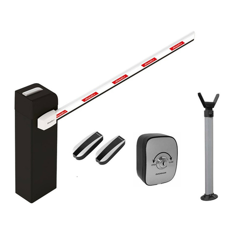
Barrier is ideal for managing access points in residential and industrial areas in moderate to heavy traffic. It suits for passage
clearances of up to 6 m. The barrier cabinet has only one spring if the boom length doesn’t exceed 3 and 4 m. If the boom length
is 6 m a second spring should be installed. The boom should be balanced irrespective of its length.
The cabinet encloses a motor, a reduction gear, a boom fastening unit, a balancing mechanism, magnetic limit switches and
a control board in a separate casing. The boom is made of aluminium profile with red light-reflectors, which are easy to see in the
dark.
The system ensures fixation of the boom in any position, that's why manual opening is possible only if the system is released.
A signal lamp is blinking when the boom moves.
1.1. SPECIFICATIONS
Parameters Characteristics
Maximum boom length 6 m
Maximum opening/closing time 6 sec / 2 sec*
Supply voltage 220-240 V, 50-60 Hz
Boom type rigid
Use intensity (at 20 °С) 70 %
Motor rotation speed 1400 rpm
Thermal protection 120 °С
Operating temperature -40…+35 °С
Rated power 300 W
Protection class IP54
# Name Quantity
1 Cabinet with integrated control block 1 pc.
2 Boom 1 pc.
3 Key-switch 1 pc.
4 User manual 1 pc.
5 Photocells 1 pair
6 V-holder 1 pc.
2. SAFETY RULES
WARNING!
To reduce the risk of injury or death read and follow all instructions. Incorrect installation and improper use of the device
could cause equipment damage and/or personal injury.
Keep these Instructions for the entire period of the barrier operation (for barrier maintenance).
Use the barrier only for its intended purpose. Any other use of this barrier system is not permitted.
Installation must be performed in accordance with EN12453 and EN 12445 standards. For non-EU countries, to obtain an
adequate level of safety, the Standards mentioned above must be observed, in addition to national legal regulations.
Prior to installation make sure that the installation site meets the climatic conditions of the barrier.
1.2. CARTON INVENTORY
After receiving the device, it must be unpacked and inspected for damage. In case of any defects, please contact the supplier
of the device.
The barrier components included in the standard delivery set are listed in the following table.
* For the barrier model Barrier-3000

3
Before installing or maintaining the equipment the main power must be disconnected.
Securely ground all metal elements of the barrier.
Verify the power supply network meets the requirements specified in this manual.
The mains power supply of the automated system must be fitted with an all-pole switch with contact opening distance of
3 mm or greater. Use of a 6A thermal breaker with all-pole circuit break is recommended.
Transport the barrier complying with all the safety requirements.
Use tools specified in Tools section hereof during assembly, installation and adjustment of the device.
Always wear protective gloves and eye protection when drilling.
To fasten the device, use the hardware supplied with the barrier or the corresponding one.
Do not make any changes to the automatic system that are not specified in this manual.
Remove the product packaging and dispose of it. Do not leave packaging materials within reach of children.
Never allow children to play in the barrier area. All remote controls, as well as stationary control buttons, must be inacces-
sible to children.
While the barrier boom is in motion no pedestrian and no vehicle shall be in the immediate vicinity of the barrier.
The manufacturer assumes no liability for damage or injury to persons or property which occur as a result of incorrect use
of the barrier.
DoorHan assumes no liability for incorrect installation or damage occurred during operation.
DoorHan Company assumes no liability for unstable operation of the automatic system when using safety devices and
accessories produced by other than DoorHan manufacturers without the approval of DoorHan.
Only original DoorHan spare parts and accessories shall be used, as other manufacturers accessories may cause the au-
tomatic system to malfunction.
Installation of accessories must be performed in accordance with EN12453 and EN 12445 standards. For non-EU countries
these requirements are to be met too.
WARNING! SHOCK HAZARD!
Have a qualified technician lay the cables 220-240 V AC. The cables must be laid in protective corrugated tubes. In case
of supply cable damage, use the suitable type of the cable.
Cables needed for installation of the barrier and accessories (if available):
cable 2 × 0,5 mm2 (photocell transmitter);
cable 4 × 0,5 mm2 (photocell receiver);
cable 3 × 1,5 mm2 (power supply);
the cables should be appropriately insulated.
SAFETY RULES

4
BARRIER UNIT
4. INSTALLATION
4.1. TOOLS
1. Set of spanners
2. Set of slotted and cross screwdrivers
3. Set of drills for metal
4. Set of drills for concrete
5. Pliers
6. Hacksaw for metal
7. Electric drill
8. Tape measure (folding rule)
1,050 mm
300 mm
up to 6 m
1 050 mm
300 mm
up to 6 000 mm
3. BARRIER UNIT
1
2
3
4
5
6
7
8
9
10
11
1. Logo plate
2. Hex bolt
3. Boom cover
4. Hex bolt
5. Boom fastening plate
6. Boom
7. Cabinet
8. Side cover
9. Control block
10. Cabinet top cover
11. LED lamp

5
INSTALLATION
4.2. INSTALLATION GUIDELINES
Follow the directions given below to install the barrier properly:
Enter the guarded territory and choose the place for the barrier cabinet.
Make sure that nothing impedes the boom travel (i.e. tree branches) and a safe clearance distance of at least 2 m is provided
between the tip of the barrier boom and the overhead power lines.
If the barrier cabinet has no protection against accidental damage by passing-by automobiles, install an additional protec-
tion means, if it is possible.
The cabinet must be installed on a concrete mounting surface. If the surface isn’t strong enough, make a foundation pit and
concrete it. Before concreting reinforce the foundation pit and lay conduit pipes to run the mains supply cable, the control
cables and the induction loop lead wires. Once the concrete has set to an adequate hardness, install the barrier cabinet.
The cabinet should be fixed to the foundation with anchor bolts or embedded concrete fittings. The depth of concreting
depends on the ground type and depth of frost penetration.
The ground must be stable. Otherwise increase the depth of the foundation pit according to recommendations of the spe-
cialists.
Make sure there are no pipes and/or electric cables running through the foundation pit.
Direct the cabinet and use a level to ensure that it is perfectly horizontal, mark and drill the bore holes for the anchor bolts.
Install the cabinet and tighten the anchor bolt nuts as shown in the picture.
Anchor
bolts
(4-M16)
Cabinet
Mounting
surface
Concrete
Nut
4.3. BOOM INSTALLATION
Remove the cabinet casing panel.
Direct the boom in accordance with opening direc tion and
insert it in the U-shaped fastening bracket.
Put on the second U-shaped bracket on the boom (as shown
in the picture).
Place and fix 4 fastening bolts.
Unlock the release (for release operation see par. 5).
Install and adjust the balancing springs using tension bolt,
so that the boom re mains stationary in any position when
the operator is released.
Resume the barrier operation locking the release.

6
INSTALLATION
WARNING! After adjusting the boom extreme positions, make sure that end switches work properly: at their triggering,
a corresponding LED on the control unit should go down. If the indicator won't go down, repeat the adjustment.
WARNING! NEXT PART OF THE MANUAL IS FOR SPECIALISTS ONLY! Incorrect adjustment may cause irreversible con-
sequences and damage your equipment. Do not perform these procedures unless absolutely necessary!
If the boom won't reach vertical or horizontal position, adjust its position with the rod located in the barrier cabinet.
Loosen nuts.
Rotate the rod counter-clockwise to raise the boom.
To lower the boom, rotate the rod clockwise.
Tighten the nuts in the necessary position.
Check the vertical and horizontal position of the boom.
Repeat the adjustment if necessary.
Levers and the rod should never be arranged in one line.
4.4. ADJUSTMENT OF BOOM EXTREME POSITIONS
4.4.1. Setting the boom closed position (red cam)
Verify the barrier is fixed rigidly. Move the barrier to the
manual control mode and move the boom to the closed
position.
Loosen the screw (pos. 1) which fastens the cam of the
boom closed position.
Move the cam till the end switch is actuated (SW1 LED
indicator at the control panel will go down).
Tighten the cam fixing screw.
Raise and lower the boom to verify that the closing end
switch operates properly.
4.4.2. Setting the boom open position (green cam)
Verify the barrier is fixed rigidly. Move the barrier to the
manual control mode and move the boom to the open
position.
Loosen the screw (pos. 2) which fastens the cam of the
boom open position.
Move the cam till the end switch is actuated (SW2 LED
indicator at the control panel will go down).
Tighten the cam fixing screw.
Raise and lower the boom to verify that the opening end
switch operates properly.
Pos. 1
Pos. 2

7
RELEASE OPERATION
5. RELEASE OPERATION
Use the lever of the integral release to release the bar-
rier.
After release is completed, the boom can be opened and
closed manually.
In order to raise or lower the boom in case of a power
failure do the following:
Turn the release lever (see the picture) clockwise till the
stop.
Raise or lower the boom manually.
In order to return to automatic control do the following:
Turn the release lever to mid-position.
Raise and lower the boom using the operator.
6. MAINTENANCE
The Barrier automatic system does not require any special servicing.
Repairs may be carried out only by a qualified technician trained and certified at an authorized DoorHan centre.
The installer shall supply all information concerning manual operation of the system in case of an emergency, and shall
hand over to the User the Manual supplied with the product.
It is highly recommended to use DoorHan original spare parts when servicing the barrier.
Carry out maintenance of the automatic system at least every six months.
Verify the boom moves smoothly when automatically operated.
Regularly check if the extreme positions of the boom travel are properly adjusted and safety devices are in good working
condition.
In case of power failure the barrier will stop. As soon as power supply is restored you can control the barrier as usual.
After expiration of life time, the item shall be delivered to a specialized disposal point!
If you have lost this Manual, you may request for the duplicate copy to the following address: Kralovsky VRCH 2018, Kadan,
43201, Czech Republic, or by e mail: [email protected].
The manufacturer (DoorHan) does not supervise barrier installation, or carry out their maintenance, thus DoorHan cannot
be held liable for safety of installation, operation and maintenance of the equipment.
7. TROUBLESHOOTING
Symptom Possible reason Solution
The barrier won't operate
Electric power is disconnected Verify the power is on
Boom movement is restricted Remove the restriction
Bad connection of electric wires Check wires connection
The barrier is released Engage the barrier
After emergency release the barrier won't operate even
after pushing the buttons of control panel or remote
control
Return to starting position was not
executed
Move the release lever to midposition
(refer to “Release operation”)
Sudden stop of the barrier Force protection is activated Adjust the barrier force
The boom lifts or lowers in jerks or stops suddenly The boom is not balanced Adjust the balancing spring
The boom won't open/close fully Wrong adjustment of the limit switches Adjust the limit switches
We very much appreciate that you have chosen
the product manufactured by our company and
believe that you will be satisfied with its quality.
For information on purchasing, distribution and
servicing contact DoorHan central office at:
120 Novaya street bld. 1, Akulovo village,
Odintsovo district, Moscow region,
143002, Russia
Phone: +7 495 933-24-00
E-mail: [email protected]
www.doorhan.com
NO. 5188, West BaoDai Road Xukou Town,
Suzhou, Jiangsu, China
Phone: +86-512-66-31-61-11
E-mail: [email protected]
www.doorhan.com
Table of contents
Other DoorHan Automatic Barrier manuals