Doosan DX380LC-5 Install guide

Serial Number 10001 and Up
Shop Manual
DX380LC-5 Excavator
950106-01236E
October 2014

Table of Contents
Page I
1Table of Contents
1 Safety 1 Track Excavator Maintenance Safety
2 Specifications 1 Specifications
3 General Maintenance 1 General Maintenance Instructions
2 Standard Torques
4Engine 1Engine
2 Engine Coolant Heater (Option)
5 Upper Structure 1Cabin
2 Counterweight
3 Hydraulic Oil Tank
4 Fuel Tank
5MainPump
6 Drive Coupling (Main Pump)
7 Main Control Valve
8 Swing Device
9 Fan Pump for Oil Cooler
10 Fan Motor for Oil Cooler
11 Joystick Valve (Work Lever)
12 Travel Control Valve (with Damper)
13 Solenoid Valve
14 Accumulator
15 Two Pump
16 Gear Pump (Rotating)
17 One Spool Valve (Rotating)
6 Lower Structure and Chassis 1 Swing Bearing
2CenterJoint
3 Travel Device
4 Track Assembly

Table of Contents
Page II
7Front 1 Boom and Arm
2 Bucket
3 Cylinders
8 Hydraulic System 1 Hydraulic System
2 Hydraulic System Testing and Adjustment
3 Hydraulic System Troubleshooting
9 Electrical System 1 Electrical System
10 Options 1OneWay
2Two-way
3 Rotating
4 Quick Coupler
11 Schematic 1 Hydraulic Schematic/Electrical Schematic

Track Excavator Maintenance Safety
1-1-1
DX380LC-5
Track Excavator
Maintenance
Safety
Edition 1

Track Excavator Maintenance Safety
1-1-5
DX380LC-5
SAFETY INSTRUCTIONS
SAFETY MESSAGES
Replace with Safety Messages Section on pages III and IV in
the Doosan Operation & Maintenance Manual.
WARNING
AVOID DEATH OR SERIOUS INJURY
Instructions are necessary before operating or servicing
machine. Read and understand the Operation &
Maintenance Manual and signs (decals) on machine. Follow
warnings and instructions in the manuals when making
repairs, adjustments or servicing. Check for correct
function after adjustments repairs or service. Untrained
operators and failure to follow instructions can cause death
or serious injury.

DX380LC-5Track Excavator Maintenance Safety
1-1-6
GENERAL
Safe Operation is Operator's
Responsibility
Only trained and authorized personnel should operate and
maintain the machine.
Follow all safety rules, regulations and instructions when
operating or performing maintenance on machine.
• Do not operate machine if you are under the influence of
drugs or alcohol. An operator who is taking prescription
drugs must get medical advice to determine if he or she
can safely operate a machine.
• When working with other personnel on a work site, be sure
that all personnel know nature of work and understand all
hand signals that are to be used.
• Be sure that all guards and shields are installed in their
proper location. Have guards and shields repaired or
replaced immediately if damaged.
• Be sure that you understand the use and maintenance of
all safety features such as safety lever and seat belt. Use
them properly.
• Never remove, modify or disable any safety features.
Always keep them in good operating condition.
• Always check for and know the location of underground
and overhead utility lines before excavating.
• Failure to use and maintain safety features according to
instructions in this manual, Safety Manual and Shop
Manual can result in death or serious injury.
Know Your Machine
Know how to operate your machine. Know the purpose of all
controls, gauges, signals, indicators and monitor displays. Know
the rated load capacity, speed range, braking and steering
characteristics, turning radius and operating clearances. Keep in
mind that rain, snow, ice, loose gravel, soft ground, slopes etc.,
can change operating capabilities of your machine.

Track Excavator Maintenance Safety
1-1-7
DX380LC-5
Proper Work Tools and Attachments
Only use work tools and attachments that are recommended by
DOOSAN for use on DOOSAN machines. When installing and
using optional attachments, read instruction manual for
attachment, and general information related to attachments in this
manual. Because DOOSAN cannot anticipate, identify or test all
attachments that owners may want to install on their machines,
contact DOOSAN for written authorization and approval of
attachments, and their compatibility with optional kits.
Attachments and attachment control systems that are
compatible with the machine are required for safe and reliable
machine operation. Do not exceed maximum operating weight
(machine weight plus attachment) that is listed on ROPS
certification plate.
Make sure that all guards and shields are in place on machine
and on work tool. Depending on type or combination of work
equipment, there is a potential that work equipment could
interfere with the cabin or other parts of machine. Before using
unfamiliar work equipment, check if there is any potential of
interference, and operate with caution.
While you are performing any maintenance, testing, or
adjustments to attachments, stay clear of the following areas:
cutting edges, pinch points, and crushing surfaces.
Never use attachment as a work platform or manlift.
Contact your DOOSAN distributor about auxiliary hydraulic kits
for attachments installation. If you are in doubt about
compatibility of a particular attachment with a machine, consult
your DOOSAN distributor.
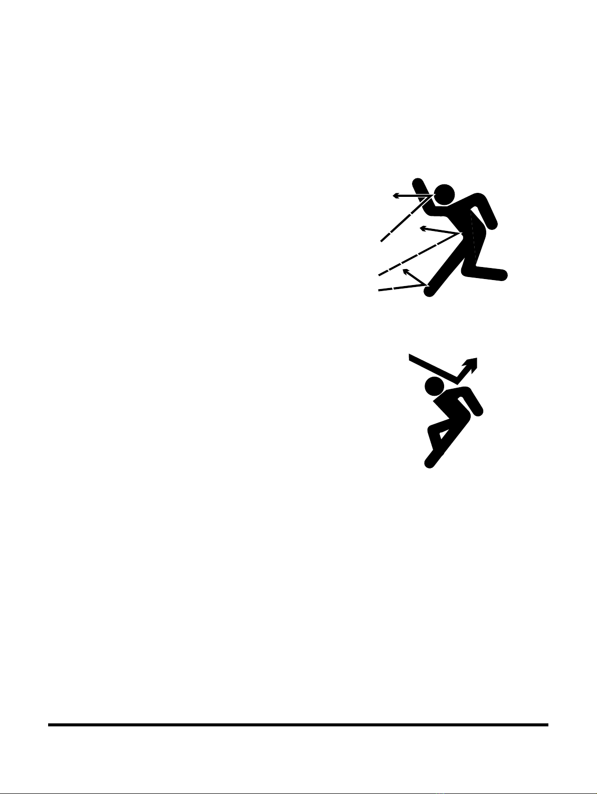
Pressurized Fluids
Pressurized air or fluids can cause debris and/or fluids to be
blown out. This could result in death or serious injury.
Immediately after operations are stopped, coolant, engine oil,
and hydraulic oil are at their highest temperatures and the
radiator and hydraulic tank are still under pressure. Always wait
for temperature to cool down. Follow specified procedures when
attempting to remove caps, drain oil or coolant, or replacing
filters. Always wait for temperature to cool down, and follow
specified procedures when performing these operations. Failure
to do so can result in death or serious injury.
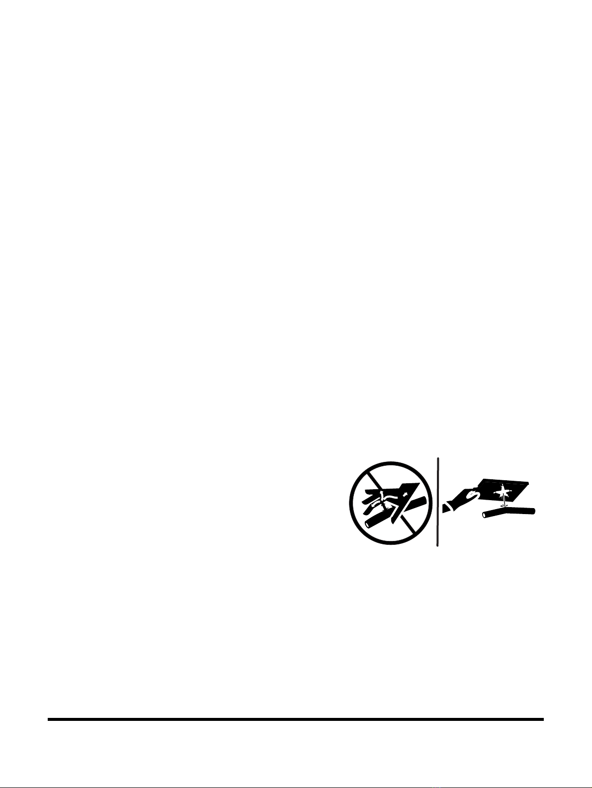
When pressurized air and/or pressurized water is used for
cleaning, wear protective clothing, protective shoes, and eye
protection. Eye protection includes goggles or a protective face
shield.
Pressure can be trapped in a hydraulic system and must be
relieved before maintenance is started.
Releasing trapped pressure can cause sudden machine
movement or attachment movement. Use caution if you
disconnect hydraulic lines or fittings.
FG018457
Figure 1

DX380LC-5Track Excavator Maintenance Safety
1-1-8
High-pressure oil that is released can cause a hose to whip or oil
to spray. Fluid penetration can result in death or serious injury. If
fluid enters skin or eyes, get immediate medical attention from a
physician familiar with this injury.
Obey all local laws and regulations for disposal of liquids.
To prevent hot coolant from spraying out, stop engine and wait
for coolant to cool. Using gloves, slowly loosen cap to relieve
pressure.
Flying or Falling Objects
On work sites where there is a potential hazard that flying or
falling objects can hit operator's cabin, select and use a guard to
match operating conditions for additional operator protection.
Working in mines, tunnels, deep pits, and loose or wet surfaces,
could produce hazard of falling rocks or flying objects. Additional
protection for operator's cabin could be required such as an
Operator Protection Guard (OPG) or window guards. Contact
your DOOSAN distributor for information on available protective
guards.
To prevent personnel from being struck by flying objects, keep
personnel out of work area.
HAOA110L
Figure 2
HAOA100L
Figure 3

DX380LC-5Engine
4-1-1
Engine
Edition 1

DX380LC-5Engine
4-1-30
Tightening Torques for Engines
IMPORTANT
Tightening torques for threaded joints in engines.
If the tightening torque is not available in the table for each
engine, refer to the special and normal tightening torques
tables.
Engine Assembly
Cylinder Block
• Piston cooling nozzle: 23 N.m
Main Bearing Cap
NOTE: The screws can only be reused 3 times. Mark the
screws each time before fitting.
• Torx screw (M19): 110 N.m + 90°
• Hexagon screw (M19): 110 N.m + 90°
Connecting Rod Cap
NOTE: The screws can only be reused 3 times. Mark the
screws each time before fitting.
1234
EX1301810
EX1301811
1234
EX1301810

Engine
4-1-31
DX380LC-5
• Torx screw: 50 N.m + 90°
• Check torque: 170 N.m
Flywheel Housing
• Lead-in union: 40 N.m ±6
Cylinder Head and Valve Package
Cylinder Head
NOTE: The screws can only be reused 3 times. Mark the
screws each time before fitting.
Cylinder head bolt, tightened in four stages
• First stage: 60 N.m
• Second stage: 150 N.m
• Third stage: 250 N.m
• Fourth stage: 90°
EX1302070
1234
EX1301810
1
2
3
4
5
6
FG020253

DX380LC-5Engine
4-1-32
Rocker Cover
• Rocker cover, upper: 18 N.m
• Rocker cover, lower: 18 N.m
Valve Mechanism
• Adjusting screw nut on rocker arm: 35 N.m

Engine
4-1-33
DX380LC-5
• Screw for rocker arm shaft bearing retainer:
90 N.m + 60°
Roller Tappet Shaft
• Banjo screw for roller tappet shaft (engines produced
earlier): 33 N.m
• Slotted screw for roller tappet shaft (engines produced
later): 40 N.m

DX380LC-5Engine
4-1-34
Crank Mechanism
Flywheel
• M18 flange screw: 180 N.m + 120°
Torsion Damper
• Torsion damper hub: 90 N.m + 30°
Timing Gear
• Intermediate gear: 50 N.m + 60°
• Camshaft gear: 20 N.m + 40°
Lubrication System
Oil sump
• Cylinder block, 8.8 screw: 26 N.m
• Cylinder block, 10.9 screw: 32 N.m
• Against cylinder block, 8.8 screw with spacer: 26 N.m
Oil Sump, Plastic
• Oil sump, spring screw: 20 N.m
EX1301830

Engine
4-1-35
DX380LC-5
Oil Plug
• Thread insert for oil plug: 320 N.m
• Magnetic oil plug, oiled seal: 80 N.m
• Magnetic oil plug, dry seal: 115 N.m
• Oil plug for filler connection in oil sump: 60 N.m
• Oil pump, 10.9 screw: 32 N.m
• Oil pump, 8.8 screw: 26 N.m
• Hose connection for cooling system: 85 N.m
• Oil filler pipe, retaining screw: 20 N.m
Oil Filter
• Element type filter, cover: 25 N.m
• Oil filter unit without loose filter element: Hand tighten

DX380LC-5Engine
4-1-36
Oil Cooler
• Oil cooler core: 26 N.m
Centrifugal Oil Cleaner
• Nut for outer cover: 15 N.m
Oil Mist Separator
• Nut (M18 x 1.5): 35 ±5 N.m
Exhaust System
Exhaust Manifold
• Cylinder head hexagon screw: 40 N.m + 60°
• Cylinder head Torx screw: 60 N.m + 60°
• Turbocharger: 50 N.m
Exhaust pipe from Turbocharger
• Turbocharger (V-clamp): 20 N.m
Turbocharger Oil Pipe
• Turbocharger lubrication pipe: 40 ±1.2 N.m (±3 %)
• Nut for turbocharger lubrication pipe: 35 ±5 N.m
Turbocharger Coolant Pipe
• Water inlet, turbocharger: 40 N.m
• Water inlet, variable geometry turbocharger electric motor: 10 N.m
EX1301840

Engine
4-1-37
DX380LC-5
Variable Geometry Turbocharger, Electric Motor
• To be tightened crosswise in two stages (Screw 12.9): 3 N.m, 11 N.m
Silencer
• Exhaust pipe to and from silencer (V-clamp): 20 N.m
Reductant Doser
• Nut (M6): 10 N.m
Charge Air Cooler
• Pipe connection (V-clamp): 8 N.m
Fuel System
Injectors
• Nut for cable connection: 2 N.m
EX1301840
EX1301840
Table of contents
Other Doosan Excavator manuals

Doosan
Doosan DX180LC Install guide

Doosan
Doosan DX220A User manual

Doosan
Doosan DX60R Install guide

Doosan
Doosan DX235LCR 2018 Manual

Doosan
Doosan DX140LC User manual

Doosan
Doosan DX300LC User manual

Doosan
Doosan DX225LC User manual

Doosan
Doosan DX140R Install guide

Doosan
Doosan DX225LC User manual

Doosan
Doosan DX140W User manual

Doosan
Doosan DX140LC User manual

Doosan
Doosan DX35Z User manual

Doosan
Doosan DX55W Install guide

Doosan
Doosan DX700LC User manual

Doosan
Doosan DX27Z User manual

Doosan
Doosan DX138LC Install guide

Doosan
Doosan DX300LC-5 Install guide

Doosan
Doosan DX380LC-7K User manual

Doosan
Doosan DX420LC User manual

Doosan
Doosan DX140LC User manual