Doran GuardianXL Quick guide

DIGITAL WEIGHT INDICATOR AND CONTROLLER
INSTALLATION AND INSTRUCTION MANUAL
DORAN SCALES, INC.
1315 Paramount Parkway
Batavia, Illinois 60510
800-262-6844
www.doranscales.com
Manual Revision 2.0
5/12/2004
P/N MAN203

1

2
TABLE OF CONTENTS
CHAPTER 1 INTRODUCTION............................................................................. 4
Unpacking the GuardianXL.................................................................................... 4
Standard Features.................................................................................................... 5
Optional Accessories .............................................................................................. 6
CHAPTER 2 SCALE OPERATION...................................................................... 8
Front Panel Features ............................................................................................... 8
Modes of Operation ................................................................................................ 9
Keypad Functions ................................................................................................. 10
CHAPTER 3 LOAD CELL INSTALLATION....................................................... 16
Load Cell Installation............................................................................................ 16
RS-232 AND I/O INSTALLATION...................................................................... 18
RS-232 Connection............................................................................................... 18
I/O Connections .................................................................................................... 19
CHAPTER 4 SETUP MODE............................................................................... 22
Configuration Methods ......................................................................................... 22
Front Panel Setup Mode ....................................................................................... 22
Setup Mode Configuration.................................................................................... 25
CHAPTER 5 CALIBRATION MODE.................................................................. 39
Configuration Methods ......................................................................................... 39
Front Panel Calibration Mode Entry..................................................................... 39
Calibration Mode Configuration........................................................................... 41
CHAPTER 6 SETPOINT CONFIGURATION ..................................................... 51
Single Trigger Setpoint Configurations................................................................ 51
Multi Trigger Setpoint Configuration................................................................... 53
CHAPTER 7 BATCH PROGRAMS.................................................................... 55
Batch Program 1 ................................................................................................... 56
Two Speed Net Weight Fill with Manual Feed .................................................... 56
Batch Program 2 ................................................................................................... 57
Two Speed Hopper Fill with Manual Dump and Fill ........................................... 57
Batch Program 3 ................................................................................................... 59
Three Speed Fill with Automatic Dump and Auto Repeat................................... 59
Batch Program 4 ................................................................................................... 61
Three Speed Loss In Weight With Manual Dump................................................ 61
CHAPTER 8 INTERNAL RELAY OPTION ........................................................ 62
CHAPTER 9 CONFIGURATION SOFTWARE................................................... 64
CHAPTER 10 INTERNAL 4-20MA OPTION...................................................... 72
CHAPTER 11 INTERNAL FIBER OPTIC OPTION............................................ 74
APPENDIX A PRINT STRING FORMATTING................................................... 76
User Print String Configuration............................................................................ 80

3
Remote Commands............................................................................................... 82
APPENDIX B SPECIFICATIONS....................................................................... 84
APPENDIX C ERROR CODES .......................................................................... 86
TABLE OF FIGURES
Figure 2.1 GuardianXL Front Panel Layout....................................................................... 8
Figure 3.1 Motherboard Load Cell Connection and Jumper Location ............................. 17
Figure 3.2 Serial and I/O Board Level Connections......................................................... 18
Figure 3.3 Example of Switch Input Connection.............................................................. 19
Figure 3.4 Example of +5 volt Relay Output Connection ................................................ 20
Figure 3.5 Example of +12 volt Relay Output Connection .............................................. 20
Figure 4.1 Menu Navigation............................................................................................. 24
Figure 4.2 Communications Parameter Menu .................................................................. 25
Figure 4.3 Date / Time Menu............................................................................................ 27
Figure 4.4 I/O and Batch configuration Menu.................................................................. 28
Figure 4.5 Test Mode Menu ............................................................................................. 35
Figure 4.6 Calibration Mode Entry Menu......................................................................... 36
Figure 4.7 Setup Mode Menu ........................................................................................... 37
Figure 5.1 Menu Navigation............................................................................................. 40
Figure 5.2 Calibration Entry Map..................................................................................... 41
Figure 5.3 Meteorological Parameters Map...................................................................... 46
Figure 5.4 Complete Calibration Mode Map.................................................................... 50
Figure 8.1 Internal Relay Control Board .......................................................................... 62
Figure 10.1 4-20mA Installation Location........................................................................ 72
Figure 10.2 Active mode................................................................................................... 73
Figure 10.3 Passive mode ................................................................................................. 73
Figure 11.1 Fiber Optic Option......................................................................................... 74
Figure 11.2 Split Bushing ................................................................................................. 75
Figure 11.3 Water Tight Assembly................................................................................... 75
Figure A.1 Indicator Dimensions...................................................................................... 85

4
Chapter 1 Introduction
Thank you for purchasing this DORAN SCALE product. The GuardianXL Weighing
System is designed to provide consistent reliability in the most demanding environments.
The GuardianXL Indicator is designed and manufactured in DORAN SCALE’s corporate
headquarters in Batavia, Illinois. DORAN SCALE’s ISO9000 certification assures that
your GuardianXL Indicator is manufactured to deliver the highest quality product
possible.
This manual describes the installation, operation and functionality of the GuardianXL
Intrinsically Safe Indicator. Please be sure to read the entire manual to leverage the
multitude of benefits that the GuardianXL provides. If any questions arise, please feel
free to contact your local DORAN SCALE distributor or the DORAN SCALE Technical
Support Department at 1-800-262-6844.
Unpacking the GuardianXL
Before unpacking your Doran product, please read the instructions in this section. Your
new GuardianXL is a durable industrial product, but it is also a sensitive instrument.
Normal care should be taken when handling and using this product. Improper handling
or abuse can damage the unit and result in costly repairs that will not be covered by the
warranty. If you notice any shipping damage, notify the shipper immediately. Please
observe the following precautions to insure years of trouble free service from your new
product.
¾DO NOT drop the enclosure.
¾DO NOT immerse the enclosure.
¾DO NOT drop objects on the enclosure.
¾DO NOT pick up the enclosure by the cables.
¾Carefully remove the enclosure from the shipping carton

5
Standard Features
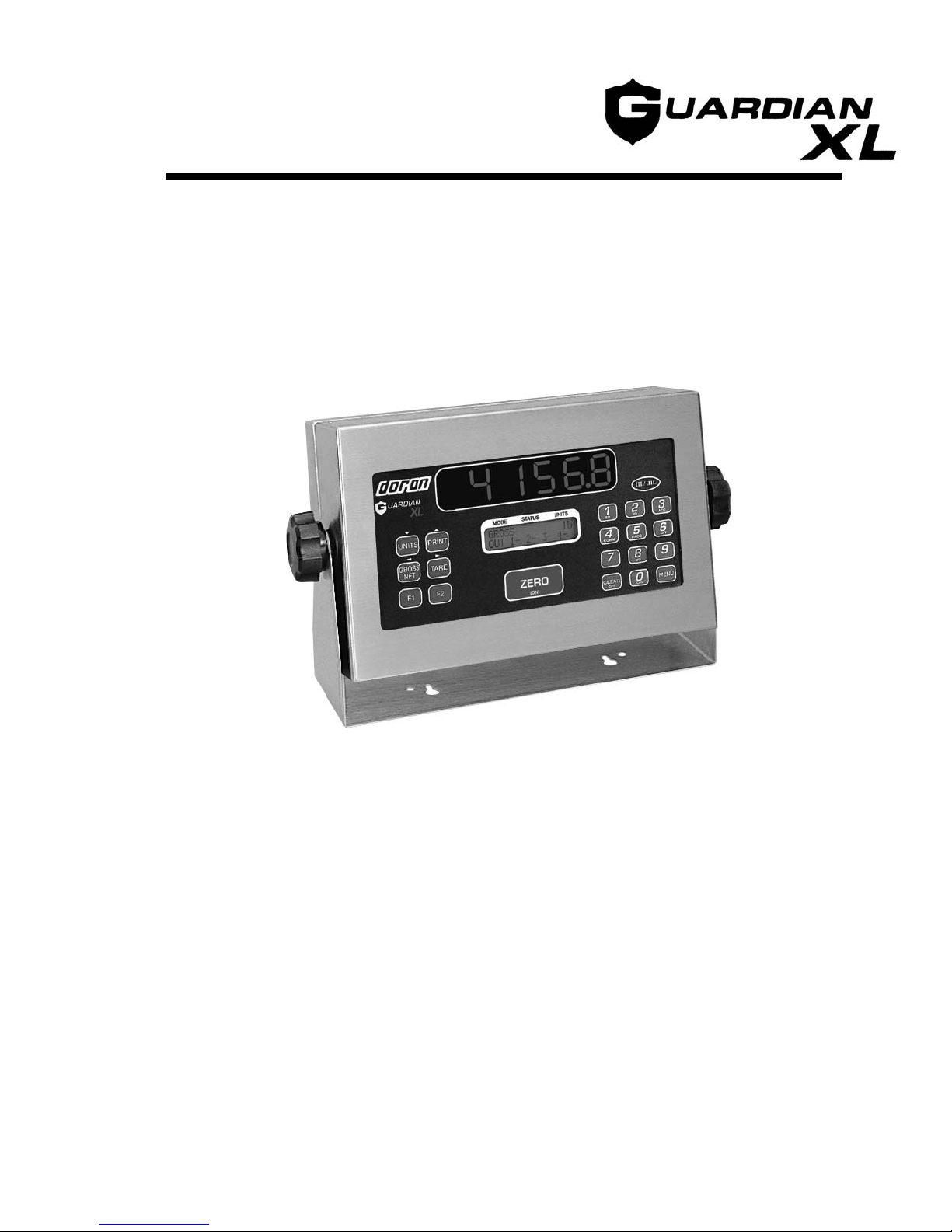
The Doran GuardianXL is a full-featured digital weight Indicator with a number of
advanced features including dual displays, keypad data entry, set points, accumulators,
ID, date & time and serial data communications capability. NTEP approved to 10,000
divisions, the GuardianXL calibration and pushbutton features can be accessed via the
front panel using a pass code. NTEP integrity is maintained by an audit trail feature that
records all metrological activity. Powered by external rechargeable battery or AC line
power, the GuardianXL carries approvals from NTEP and Factory Mutual.
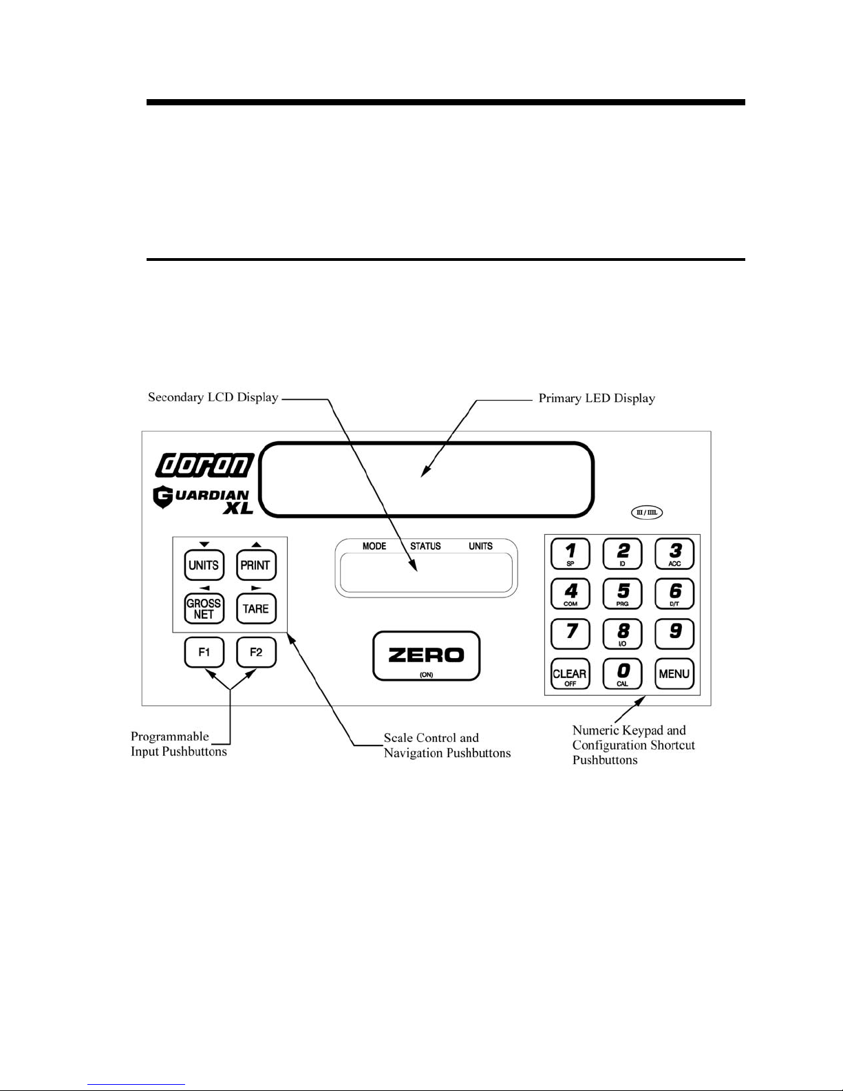
¾Dual Displays – Bright, highly visible, 1” high, 6 digit, red LED display is the
primary digital weight display. A two line, 32 character, alphanumeric, backlit
Liquid Crystal Display (LCD) provides custom messaging for excellent user
feedback, including Mode, Status and Units.
¾Zero – Pushbutton ZERO up to 100% of scale capacity.
¾Tare – A tare value can be entered in two ways – pushbutton tare or digital tare entry.
¾Keypad Data Entry – Numeric keypad for digital entry of tare and set point values.
Numeric pushbuttons have dual function to access pushbutton indicator functions.
¾Gross/Net – Display gross or net weight at the push of a button
¾Units – Selects up to 6 weight display units – lb, kg, g, oz, lb&oz or user units.
¾Print – Activates a serial data transmission to external devices
¾Accumulator and Counter – automatically accumulates gross and net weight.
Standard print string available for accumulator and counter output.
¾Time & Date
¾Digital Calibration – Set via front panel with operator pass code, and recorded in
two audit trail memory. Select any capacity value and the corresponding resolution
will be automatically selected. Zero and Span are independently set, allowing for
easy calibration in large scale filling or hopper applications.
¾Resolution – Display resolution from 200 to 50,000 divisions.
¾Update Rate – Select from 5.5 to 11 updates/second
¾Digital Filters - Wide selection of digital filter settings for maximum stability in the
presence of vibration or air movement.
¾Auto Zero Tracking feature compensates for small changes in zero and is selectable
from 0.5 to 5.0 divisions.
¾Full Duplex RS-232 Communications standard
¾Digital I/O Standard – Access to four TTL inputs and four TTL outputs on board.
¾Microprocessor Watchdog System monitors operation to prevent scale failure or
lock-up under severe fault conditions.
¾Approvals – NTEP Class III certification to 10,000 divisions.

6
Optional Accessories
¾Internally Mounted Relay Control Board
¾Fiber Optic Communications
¾Digital I/O Controls Including:
¾Switch Input
¾RS-232 Output
¾Optional Fiber Optic Input
¾Optional Relay Output
¾Optional Remote Display
¾4-20mA Analog Output passive and active

7

8
Chapter 2 Scale Operation
The GuardianXL has many advanced features. This Chapter will describe how to operate
an installed and functioning GuardianXL indicator.
Front Panel Features
The GuardianXL is equipped with a 19 pushbutton keypad. The layout is shown in
Figure 2.1 below. The GuardianXL display is divided into five areas.
Figure 2.1 GuardianXL Front Panel Layout
Primary LED Display
The primary display consists of six bright, 1” high, seven-segment red LED digits. These
digits typically display the current weight and are visible up to 50 feet away.
Secondary LCD Display
The two line 32-digit alphanumeric backlit LCD display provides feedback to the user.
This display is primarily used for displaying the gross / net mode, center of zero status,
motion, displayed units, setup mode and calibration mode information.

9
Scale Mode Control and Navigation Pushbuttons
The blue pushbuttons on the left of the touch panel controls the displayed units, gross /
net mode, tare, print and programmable pushbuttons. These pushbuttons also navigate
through the setup and calibration modes.
Numeric Keypad and Configuration Shortcut Pushbuttons
The purple numeric keypad is used to enter data for tares, setpoints and setup
configuration. The setup and calibration mode is entered through shortcut pushbuttons
that have setup and calibration menu abbreviations below the numbers on the keypad.
These dual function shortcut pushbuttons provide quick access to specific parameters in
the setup and calibration modes.
Scale Zero Pushbutton
This is the most often used feature of the indicator. Therefore the ZERO pushbutton is
centered on the front panel and the largest pushbutton on the GuardianXL.
Modes of Operation
Weighing Mode
The weighing mode of the GuardianXL is the most commonly used mode. While in this
mode, the primary display will indicate current weight and the secondary display will
indicate gross / net, center of zero, motion and displayed weight units. The rest of this
Chapter describes this mode in detail.
Output Mode
The output mode is only active while the GuardianXL is in the weighing mode and when
any output is enabled. The second line of the secondary display will indicate the status of
each setpoint output while the indicator displays all weigh information included in the
weighing mode. A sample output status line is “1- 2- 3- 4*” where a dash to the right of
the output number indicates an inactive output while an asterisk to the right of the output
number indicates an active output. Outputs are accessible at terminal block TB3 or by
the Digital I/O option. Setpoint configuration is described in Chapter 6.
Batch Mode
The batch mode controls outputs in a batch sequence. Batch sequences require no
programming to implement, simply select a canned batch sequence from the menu and
the program is ready to run. The second line of the secondary display will indicate the
status of each setpoint output while the indicator displays all weigh information included
in the weighing mode. A sample output status line is “1- 2- 3- 4*” where a dash to the
right of the output number indicates an inactive output while an asterisk to the right of the
output number indicates an active output. If a standard batch sequence does not meet
your needs, the batch sequence can be altered by changing setpoint configurations. The
batch mode is fully described in Chapter 7.

10
Setup Mode
The setup mode allows configuration of the standard non-metrological parameters for the
GuardianXL. A standard parameter is one that cannot affect the weighing mode of the
scale. For instance fiber optic output, auto sleep delay, accumulator and setpoint values
are examples of these standard parameters. These standard parameters can be easily
accessed through shortcut pushbuttons, or protected with a pass code. Setup mode
parameter configuration is described in detail in Chapter 4.
Calibration Mode
The calibration mode allows configuration of the metrological makeup and calibration of
the GuardianXL. Sealed parameters are those that can affect the weighing mode of the
GuardianXL. Access to this mode can be done through the entry of a pass code or by
pressing the sealed calibration switch located inside the GuardianXL housing in
combination with a pass code. Only authorized DORAN SCALE distributors are factory
trained to configure the GuardianXL. For information relating to your nearest DORAN
SCALE authorized distributor call DORAN SCALE’s Sales Department at
1-800-262-6844. Detailed calibration instructions are described in Chapter 5.
Test Mode
The GuardianXL provides a test mode for the outputs, fiber optic communications, serial
port and 4-20mA option. See Chapter 4, Scale Test Mode section for more information.
Keypad Functions
ZERO / Scale Power On
The ZERO pushbutton is also used to zero the scale prior to making a reading. The
ZERO pushbutton functions over the full range of the scale in standard operation. In
legal for trade mode, it will be limited to a zero band equal to +1.9% of scale capacity.
When the indicated weight is within the center of zero band (gross zero + 0.25 division)
the secondary display will indicate→0←in the center of the secondary display.
To zero the scale in gross mode, wait until the scale is stable and press the ZERO
pushbutton. The scale will zero immediately.
The ZERO function will also work while the scale is in net mode. When in net mode,
press zero and the scale will return to gross mode, zeroing out the scale weight. The tare
value is saved and the scale can still switch from gross to net mode. This feature is useful
when there is a consistent tare value used, but unwanted material is spilled onto the base
surface between weighments.

11
TARE
A tare weight can be entered on the GuardianXL in two ways – Pushbutton Tare or
Digital Tare entry.
To use Pushbutton Tare, simply place the tare item on the scale platform and press
TARE. The scale will store this tare weight, automatically switch to Net weight mode
and display zero weight. If you switch to the Gross mode by pressing the GROSS/NET
pushbutton, the actual tare weight will be displayed. If the tare item is then removed from
the scale, the scale will display the negative tare weight in the Net mode and zero in the
Gross mode.
To enter a Digital Tare, enter the weight through the keypad. The tare must be a positive,
non-zero weight. This will place the indicator into entry mode and once the desired
weight is entered press TARE to save the tare weight. If any errors are made while
entering the tare weight, press CLEAR and reenter the weight. After the tare weight is
stored, the scale will show zero in the Net mode when the tare item is on the scale. When
the scale is empty, the scale shows the negative tare weight in the Net mode and zero in
the Gross mode.
To recall the tare weight at any time, press MENU and TARE. The main display will
indicate the tare weight in the currently selected units. The secondary display will show
“RECALL TARE”. To exit this mode press CLEAR.
To clear a tare weight press 0 on the keypad then TARE. This will remove the tare from
memory. If not cleared, the TARE weight will remain in memory, even if the indicator is
turned off.
GROSS / NET
Press the GROSS / NET pushbutton to switch the display mode from gross weight to net
weight, or from net to gross modes. The current mode is indicated on the secondary
display with the word “GROSS” or “NET”. If a tare value has been entered, then the net
value is the gross weight less the tare weight. If a tare is not currently stored, the display
remains in gross mode when the GROSS / NET pushbutton is pressed. When a tare is
entered the GuardianXL switches to the Net mode automatically.
UNITS
The UNITS pushbutton permits the operator to select from six displayed weight units.
Simply press the UNITS pushbutton and the secondary display will indicate the correct
weight in the current weight unit “lb”, “kg”, “g”, “oz”, “lb-oz” or “user”. The UNITS
pushbutton can be configured to allow the selection of any combination of units listed
above, preventing accidental selection of undesired units.
PRINT
The PRINT pushbutton transmits print string data via an RS-232 cable or through the
Fiber Optic option. This feature is also used in conjunction with the Digital I/O to relay
control commands.

12
CLEAR
The CLEAR pushbutton is used to cancel any digital entry from the keypad. Pressing
CLEAR when the secondary display reads “ENTRY” will return the scale to the weigh
mode from a digital entry mode.
F1, F2 Programmable Pushbuttons
These pushbuttons can be programmed as an output or function trigger and also act as
batch controls while in the batch mode. See Chapter 4, Setpoint Output and I/O Function
Parameters for details. See Chapter 7 for batch mode information.
MENU
The MENU pushbutton allows access to tare recall, and general configuration of the
GuardianXL including: setpoints, preacts, accumulators, RS-232 port, date/time and
calibration access. Pressing MENU, then a shortcut pushbutton on the numeric keypad
accesses these configuration features and the non-calibration menu. There are nine
shortcut pushbuttons on the numeric keypad. Each shortcut pushbutton has an
abbreviated feature name accompanying the number on a numeric pushbutton. Each of
these shortcut features is described below. To avoid accidental entry into these features,
access can be eliminated through the use of a pass code. See Chapter 4 to learn about the
features briefly described below in detail.
Programming and Recalling Setpoint & Preact Weight Values
(MENU – SETPOINT)
The GuardianXL has four Setpoints and four Preacts. To access the Setpoint or Preact
weight values, press MENU, then 1 (SP) on the numeric keypad. This key sequence
places the GuardianXL into the recall mode. The primary display will show the stored
weight value and the polarity. The secondary display will show “RECALL SP 1” when in
the recall Setpoint mode or “RECALL PREACT 1” for the recall Preact mode. Press
numbers 1, 2, 3 or 4 on the numeric keypad once, to recall the respective setpoint value.
Press any of the same numeric key twice will recall the respective Preact value. When
review of the Setpoint or Preact values is complete, press CLEAR to exit the recall mode.
To program a Setpoint or Preact weight value, simply enter the weight value using the
keypad. This places the GuardianXL into the “ENTRY” mode and the weight value is
echoed to the primary display. Use the UNITS key only to toggle the polarity of the
setpoint weight value. If an error is made when entering the weight, press CLEAR to exit
the entry mode. When the number is correctly displayed press MENU and the secondary
display will read “SETPOINT ENTRY” and ”SELECT 1,2,3,4,M”. Press the number of
the setpoint (1, 2, 3 or 4) you want to save the current displayed weight. Press the MENU
to enter the Preact entry mode, the secondary display will read “PREACT ENTRY” and “
SELECT 1,2,3,4,M” Press the number of the Preact (1, 2, 3 or 4) you want to save the
current displayed weight.
After the value is saved the scale will return to the weigh mode. Setpoint and Preact
configuration is covered in detail in Chapter 4 and 6.

13
Scale ID (MENU – ID)
Allows entry of the scale ID number. To configure the scale ID, press MENU then
CLEAR. The secondary display will read “SET SCALE ID ENTER ID NUMBER”.
Simply enter the scale ID number – up to 6 digits and press ZERO to accept.
Accumulator and Counter (MENU – ACCUMULATOR)
This displays the value of the accumulator and counter. The maximum value for the
accumulator and counter is limited to six digits, i.e. 999999. When the maximum value
is reached, the accumulator will not accumulate and the secondary display will read
“ACCUMUALTOR ERROR”.
Press MENU 3 (ACC) to enter the accumulator recall mode. The secondary display will
read “GROSS ACCUM lb ACCUM RECALL”. The accumulator recall mode will
display the accumulator value in the units currently selected in the weigh mode as well as
either gross or net mode. To toggle between the gross and net values press the GROSS /
NET pushbutton. A net accumulator value can only be accessed by having an active tare
in the weigh mode.
To clear the accumulator and counter values, press CLEAR while in the accumulator
recall mode. The accumulator counter is incremented once every time a manual or
automatic accumulation occurs. The counter value cannot be displayed on the front
panel.
The counter value can be printed using the Fiber Optic option. When in accumulator
recall mode, press PRINT to execute a print string that contains the gross accumulated
weight, net accumulated weight and counter. See Appendix A, Accumulator Print String
for print string formatting.
Accumulating of weights is possible with an auto accumulate function. See Chapter 6,
Single Trigger Setpoint Configurations for an automatic accumulate configuration. To
exit the accumulator recall mode, press MENU.
Fiber Optic Communications Protocol (MENU – COMMUNICATIONS)
Pressing MENU then 4 (COMM) on the numeric keypad places the GuardianXL into the
setup mode. To exit to the weigh mode, press MENU. See Chapter 4, Communications
Parameters for configuration details.
Batch Programming (MENU – PROGRAM)
Pressing MENU then 5 (PRG) See Chapter 7 for batch mode programming information.
Date Time (MENU – DATE / TIME)
This allows recall of the current date and time. Press MENU to exit the date time recall
mode. To change the date and time see Chapter 4, Date Time Parameters.

14
I/O Configuration (MENU – I/O)
Pressing MENU then 8 (I/O) on the numeric keypad places the GuardianXL into setup
mode. To exit to the weigh mode press MENU. Refer to Chapter 4 and 6 for I/O
configuration.
Audit Trail and Calibration (MENU – CALIBRATION)
Pressing MENU then 0 (CAL) on the numeric keypad places the GuardianXL into the
calibration mode. This shortcut pushbutton allows access to the entire calibration mode.
The audit trail counter is displayed in the primary display, while the secondary display
reads PARAMETER AUDIT. The parameter audit trail tracks changes in metrologically
related parameters in the calibration mode by incrementing every time changes are saved
to the GuardianXL.
Press TARE () to advance to the calibration audit trail counter. The calibration audit
trail counter is displayed in the primary display, while the secondary display reads
CALIBRATE AUDIT. The calibration audit trail tracks changes in calibration by
incrementing every time the GuardianXL is calibrated. Press TARE () to advance to
the calibration mode entry point. The secondary display will read ACCESS CAL MODE
ENTER PASS CODE. Access to the calibration mode requires a pass code. For detailed
calibration mode menu configurations refer to Chapter 5.

15

16
Chapter 3 Load Cell Installation
Connecting a load cell or configuring jumpers requires the removal of the rear panel.
Follow the GuardianXL Installation Manual guidelines for working with the GuardianXL
in a hazardous environment.
Removing the Rear Panel
Before you remove the rear panel, remove the AC power from the GuardianXL.
Removing the rear panel requires a 5/16” nut driver. Remove all four screws and set
aside. Do not loosen any water tights on the back panel that do not require modification.
Replacing the Rear Panel
Secure any connections that have been modified. When replacing the rear panel it is
necessary to mount the gasket, all four screws and gasket washers. Tighten all four
screws to 20 ft-lb to achieve proper sealing. It is normal for the rear panel to dimple
slightly when the screws are tightened to 20 ft-lb. Tighten any modified watertight until
the cable exiting the watertight can no longer slide through the watertight – this is usually
finger tight. With an open-end wrench, apply a quarter turn to the watertight for a tight
seal.
Load Cell Installation
Single Load Cell Installation
To install a single load cell, remove the rear panel and check the JU3 and JU4 jumper
configuration. Remove JU3 and JU4 for a six-wire load cell. Inversely, JU3 and JU4
must be in place for a four-wire load cell. To install the load cell wires, press the load
cell connector arm back with either your finger or a non-conductive object.
Multiple Load Cell Installation
Four load cell systems will degrade the battery life between charging due to the
additional load placed on the electronics. It is recommended that multiple load cell
installations use 1000 Ωload cells.

17
Figure 3.1 Motherboard Load Cell Connection and Jumper Location

18
RS-232 and I/O Installation
The GuardianXL comes standard with an RS-232 port, four inputs and four outputs
available on board. This section will describe the connections and use of these features.
The RS-232 and I/O connections are located on the lower left quadrant of the
motherboard. The layout of all connections is shown in figure 3.2 below.
Figure 3.2 Serial and I/O Board Level Connections
RS-232 Connection
RS-232 is a basic three conductor serial communications interface commonly used with
printers, computers and other microprocessor based electronic equipment. The
configuration of the RS-232 port is discussed in Chapter 4, Chapter 10 and Appendix A.
Also, Doran offers a basic introduction to RS-232 communications (P/N MAN214) and
its’ use with Doran indicators. This section will provide board level connection and
cabling information.

19
RS-232 Motherboard J1A Connections
J1A Pin Function
1 Transmit Simplex (TXD2)
2 Transmit Duplex (TXD)
3 Receive Duple (RXD)
5 Signal Ground (GND)
DB9 Female Connector Wiring
DB9 Pin Function
2 Transmit (TXD)
3 Receive (RXD)
5 Signal Ground (GND)
DB25 Female Connector Wiring
DB25 Pin Function
3 Transmit (TXD)
2 Receive (RXD)
7 Signal Ground (GND)
I/O Connections
Inputs
Four inputs are available on the motherboard. Inputs can be programmed as a remote
switch, a trigger for an output or a batch sequence input. All configuration information
for inputs is available in Chapters 4, 6 and 7. A sample circuit for an input connection is
shown in figure 3.3.
Figure 3.3 Example of Switch Input Connection
WARNING: applying voltage other than 0 to +5 volts to any of the inputs may result in
damage to the motherboard.
Table of contents
Other Doran Accessories manuals