DORIC Electrical Rotary Joint User manual

Electrical Rotary Joint
User Manual
Version 1.1.1

Contents
1 Overview 3
1.1 Electrical Rotary Joint .................................................. 3
1.2 Electrical Rotary Joint Holders ............................................ 4
1.3 Rotary Joint Harwin 12/Omnetics PZN12 Adapter Kit .............................. 5
2 Operations Guide 6
2.1 Rotary Joint Holders .................................................. 6
2.2 Electrical & Optical Cables ............................................... 9
3 Specifications 12
4 Support 14
4.1 Maintenance ....................................................... 14
4.2 Warranty ......................................................... 14
4.3 Contact us ........................................................ 14
2

1
Overview
1.1 Electrical Rotary Joint
(a) Rotary Joint (b) Rotary Joint Stator (black) and Rotor
(yellow)
Figure 1.1: Electrical Rotary Joint
The Doric Electric Rotary Joint is used to transmit electrical signal from a moving sample to a fixed recording system. It
consists of high precision ball bearings and of a slip ring to transmit signal. It is composed of a Stator, which stays immo-
bile, and a Rotor that moves (Fig. 1.1b). The electrical signal is transmitted through 2 possible types of connectors: Male
Harwin (6 or 12 contacts) or Female HDMI (Blackrock micro compatible pinout available). This is a device intended for
fundamental research, for use with rats and larger animals. The central clearance hole is used in cases where electrical
and optical signal is required. It allows for passage of one or two optical fibers with M3 or ferrule/sleeve connectors.
3

1.2 Electrical Rotary Joint Holders
The rotary joint is provided with 3 holders: the Holder ERJ,Holder FRJ large and the Holder FRJ small (Fig.1.1). To com-
bine electrical and optical signal, the Holder ERJ can be used in combination with the Holder FRJ small or the Holder FRJ large.
If the rotary joint is used only for electric signal, the Holder FRJ large alone (Fig.1.1). The gimbal mount GH FRJ (Fig.1.1)
can also be used with the rotary joint alone, while allowing moderate rotation along 2 axes.
Table 1.1: Electrical Rotary Joint Holders
Holder ERJ
Holder FRJ small
Holder FRJ large
Gimbal Holder (GH FRJ)
Chapter 1. Overview 4

1.3 Rotary Joint Harwin 12/Omnetics PZN12 Adapter Kit
To integrate the rotary joint within electrophysiology systems that use Omnetics PZN-12 connectors, an adapter kit
can be provided. These elements allow a Harwin-connectorized rotary joint to serve as a rotary joint for Omnetics con-
nectorized systems. The adapter system is composed of the following elements.
Figure 1.2: Harwin-Omnetics Adapters and Parts
• The MIRROR Adapter is a cable with a Female Harwin 12-pin connector on one side and a Omnetics PZN12
connector on the other. To use, simply insert the Female Harwin connector in the Male Harwin connector on
the Stator side of the rotary joint. The pinout inside this adapter is mirrored to take into account the connector
mirroring in a Omnetics PZN12/Omnetics PZN12 cable.
• The STRAIGHT Adapter is a simple Female Harwin 12-pin connector/Omnetics PZN12 connector adapter. To
use, simply insert the Female Harwin connector in the Male Harwin connector on the Rotor side of the rotary
joint.
Figure 1.3: Adapters Connected to AHRJ (example), STRAIGHT on Rotor (yellow) and MIRROR on Stator (black)
Chapter 1. Overview 5

2
Operations Guide
2.1 Rotary Joint Holders
2.1.1 Holder ERJ
(a) (b)
(c) (d)
Figure 2.1: Installation of the rotary joints in the Holder ERJ
6

1. Deposit the Holder ERJ frame on the base (1) and secure using #8-32 or M4 screws (2) and bolts (3) (Fig. 2.1a).
The holder can be installed in an experimental setup using 1/4 (or M6) screws and nuts.
2. Install the Electrical Rotary Joint in the Holder ERJ base (Fig. 2.1b) and secure it in place using the 3/4-32 UN secur-
ing bolt (Fig. 2.1c).
3. The 1x1 Fiber-optic Rotary Joint must first be set up in the Holder FRJ small, using the directives in the 1x1 Fiber-
optic Rotary Joint User Manual, to be installed. The Holder FRJ small is then be attached to the Holder ERJ frame (1)
using 1/4 (or M6) screws (2) and bolts (3) (Fig. 2.1d). See Figure 2.2a for the final result.
For installation using the 1x2 Fiber-optic Rotary Joint - Intensity division or the 1x2 Fiber-optic Rotary Joint - Wave-
length division, the rotary joint must first be installed in the Holder FRJ large using the directives in the 1x2 Fiber-
optic Rotary Joint User Manual. The Holder FRJ large is then attached to the frame in the same fashion as with an
1x1 Fiber-optic Rotary Joint. See Figure 2.2b for the final result.
(a) With 1x1 Fiber-optic Rotary Joint (b) With 1x2 Fiber-optic Rotary Joint - Intensity
division
Figure 2.2: Holder ERJ
Chapter 2. Operations Guide 7

2.1.2 Holder FRJ large
The rotary joint is to be screwed into the Holder FRJ large (Fig. 2.3). Ensure the stability of the rotary joint in the thread
to avoid slippage during use. The holder can be installed in a experimental setup using 1/4 (or M6) screws.
Figure 2.3: Installation of the ERJ in the Holder FRJ large
2.1.3 GH FRJ
The Gimbal Holder allows swivel movement of the rotary joint along 2 axes. The rotary joint is to be threaded into the
holder (Fig. 2.4). Ensure the stability of the rotary joint in the thread to avoid slippage during use. The holder can be
installed in a experimental setup using #8-32 screws.
Figure 2.4: ERJ in the Gimbal Holder
Chapter 2. Operations Guide 8

2.2 Electrical & Optical Cables
2.2.1 Electrical Cables
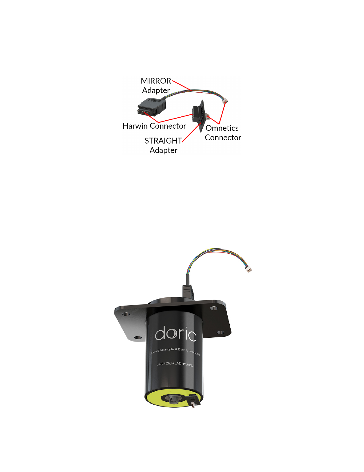
The rotary joint is assembled using either HDMI or Harwin (6 or 12 contacts) electrical connectors. The number of
electrical contacts does not necessarily equal the number of recording channels. The system requires a signal cable
(connecting to a console, computer or other signaling device) and a subject cable (connecting to the experimental sub-
ject).
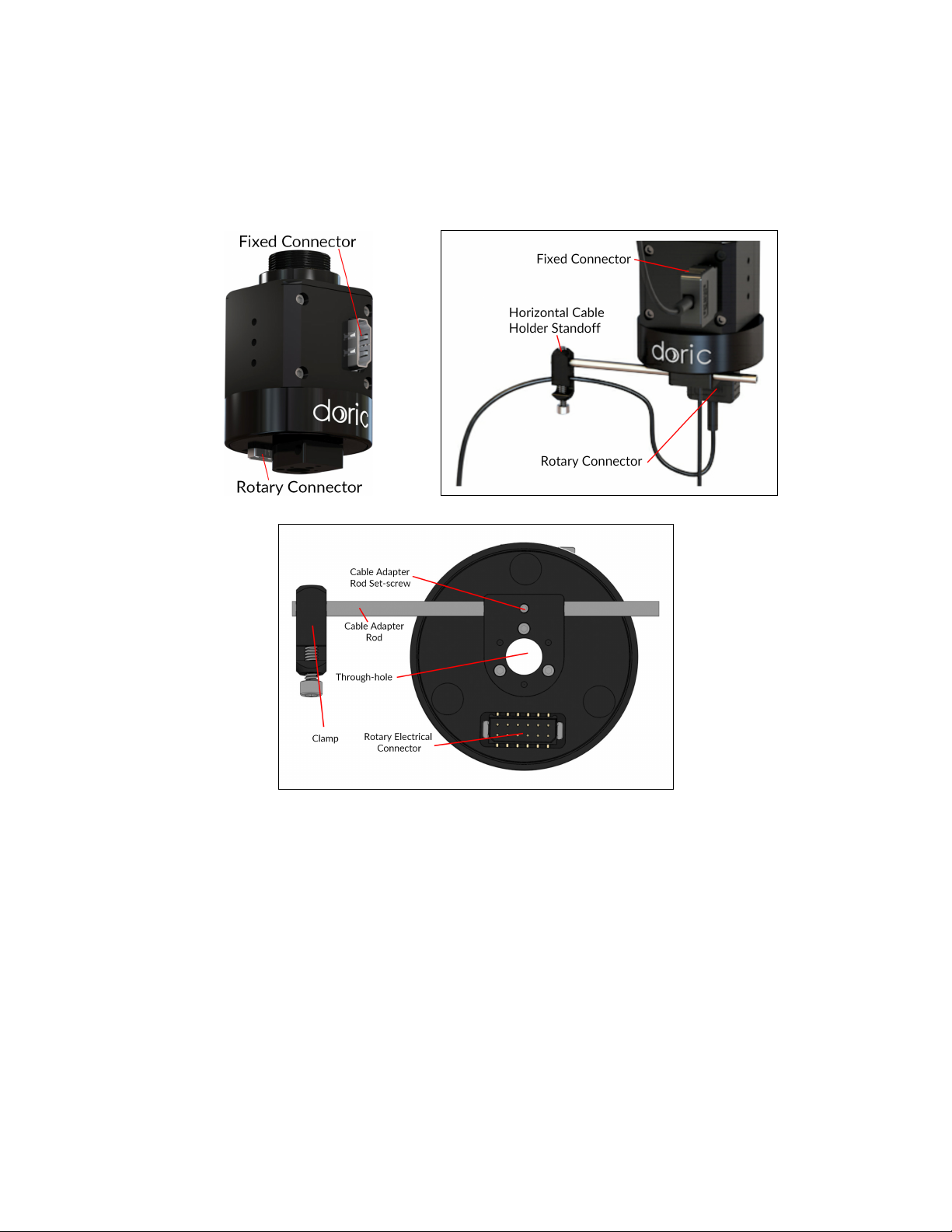
(a) Electrical Connectors (b) Cable Placement
(c) Electrical Rotary Joint Underside
Figure 2.5: Electrical Connector Placement
1. Ensure that the electrical connectors are free of dust using an air duster before installing the cables. When not in
use, install plastic caps on connectors for protection and cleanliness.
2. Connect the signal electrical cable to the fixed electrical connector (Fig. 2.5a and 2.5b).
3. Connect the subject electrical cable to the rotary connector (Fig. 2.5a and 2.5b).
4. If using the Horizontal Cable Holder, the subject electrical cable can be looped into the Cable Holder Standoff
(Fig. 2.5b) to provide extra torque. The cable is secured into the clamp (Fig. 2.5c) using a #4-40 nylon socket-head
cap screw. See section 2.2.2 for the installation of the Horizontal Cable Holder.
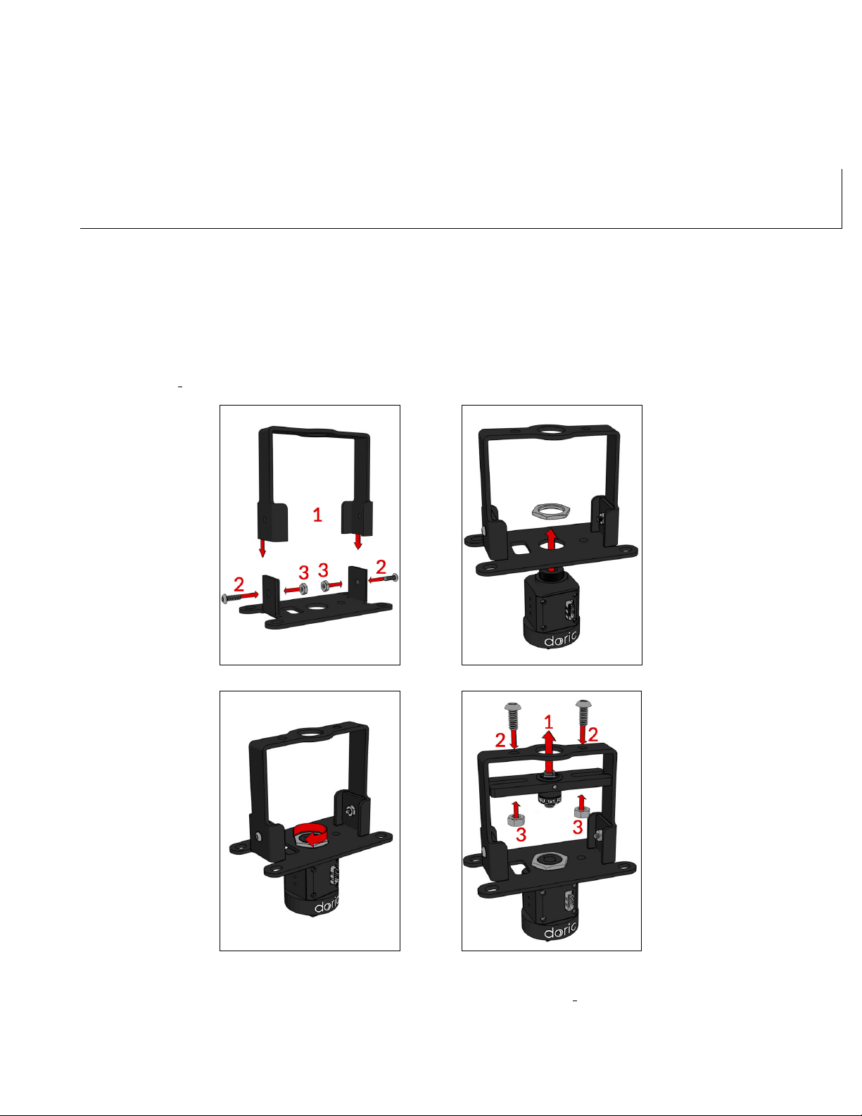
2.2.2 Horizontal Cable Holder
The horizontal cable holder keeping electrical cables off-center can be added to increase the effective torque applied on
the rotor. To install the Horizontal Cable Holder:
Chapter 2. Operations Guide 9

1. Slide the cable holder rod with the cable clamp facing down into the pre-installed adapter situated under the rotary
joint (Fig. 2.6). The rod is held in place using a 2-56 set-screw on the underside of the adapter.
2. Secure the clamp (facing down) onto the cable adapter rod using a #4-40 nylon set-screw (Fig. 2.6).
Figure 2.6: Horizontal Cable Holder Standoff Placement
2.2.3 Optical Fibers
The ERJ can be used alongside an optical rotary joint. If using optical fiber patch cords and a Fiber-optic Rotary Joint,
follow these directions. The system requires a signal patch cord (connecting to a light source) and a subject patch cord
(connecting to the experimental subject).
1. Connect the signal patch cord to the fixed connector of the optical rotary joint.
2. Install the ERJ Holder as shown in section 2.1.1.
3. Select the subject patch cord(s) for usage. One side must be terminated with an FC connector and the other with
aM3 or Ferule/Sleeve connector.
4. Connect the subject patch cord(s) FC connector to the rotary connector. Follow the directions in the manual of
the rotary joint.
5. Pass the patch cords through the Through-hole (Fig. 2.5c). Only M3 or Ferrule-sleeve connectors are small
enough to pass through.
6. Do not secure the patch cord(s) in the Horizontal Cable Holder. For proper rotation, they must be hung loosely.
The patch cord(s) must not rub against the side of the through-hole.
Chapter 2. Operations Guide 10

Figure 2.7: Electrical and Fiber-optic Rotary Joints - Cable Installation
Chapter 2. Operations Guide 11

3
Specifications
Table 3.1: Harwin Electrical Connector Configuration
Male (on rotary joint) Female (on adapter)
Table 3.2: HDMI Electrical Connector Configuration
Male (on cable) Female (on rotary joint)
Table 3.3: HDMI Electrical Connector Pinouts
HDMI Microscope HDMI Blackrock 2
12

Table 3.4: General Specifications
SPECIFICATIONS VALUE NOTES
HDMI connector pinout type Microscope, Blackrock 2 Female connector
Harwin connector type Datamate L-Tek serie Male connector, 2 mm pitch, 12 contacts, 2 rows
Number of contacts 6 or 12 -
Contact material Gold -
Maximum current 2 A per contact -
Contact resistance <500 mΩ-
Resistance variation during rotation <100 mΩ5 VDC During constant rotation
Start up torque 0.9 mN·m (for 6 contacts) Typical Value
1.9 mN·m (for 12 contacts) Typical Value
Rotation speed up to 300 rpm -
Outer diameter 45.0 mm -
Through-hole diameter 7.5 mm -
Length 59.4 mm -
Mass 123.0 g -
Table 3.5: Recommended Environmental Specifications
DESCRIPTION OPERATION STORAGE
Use Indoor Indoor
Temperature 0-40 ◦C 0-40 ◦C
Humidity 40-60% RH, non condensing 40-60% RH, non condensing
Chapter 3. Specifications 13

4
Support
4.1 Maintenance
The product does not require any maintenance. Do not open the enclosure. Contact Doric Lenses for return instructions
if the unit does not work properly and needs to be repaired.
4.2 Warranty
This product is under warranty for a period of 12 months. Contact Doric Lenses for return instructions. This warranty
will not be applicable if the unit is damaged or needs to be repaired as a result of improper use or operation outside the
conditions stated in this manual. For more information, see our Website.
4.3 Contact us
For any questions or comments, do not hesitate to contact us by:
Phone 1-418-877-5600
Email sales doriclenses.com
© 2019 DORIC LENSES INC
357 rue Franquet - Quebec, (Quebec)
G1P 4N7, Canada
Phone: 1-418-877-5600 - Fax: 1-418-877-1008
www.doriclenses.com
Chapter 4. Support 14
Table of contents
Popular Recording Equipment manuals by other brands

Behringer
Behringer Xenyx 1222FX user manual

Schlockwood
Schlockwood SW200 Set up and operating guide

radioRA
radioRA GRAFIK Eye RA-GRXI Setup guide addendum

Sound Devices
Sound Devices 744T User guide and technical information

R.M. Young
R.M. Young 32500 quick start guide

Toshiba
Toshiba Surveillix EAV Series quick start guide