Prosecure Opti Motion Stereo
—
Änderungen vorbehalten
Subject to change without notice
DORMA Deutschland GmbH DORMA Platz 1 58256 ENNEPETAL Tel. +49 2333 793-0 Fax +49 2333 793-4950
www.dorma.com
EC DECLARATION OF CONFORMITY
A complete version of the EC declaration of conformity is available at www.dorma.com.
DORMA GmbH + Co. KG DORMA Platz 1 58256 Ennepetal
declares that the products Prosecure Opti Motion Mono/Stereo and Prosecure Easy Motion Mono/Stereo
comply with the provisions of the EC Directive(s) specified in the Appendix and that the standards and/or technical specifica-
tions referred to in the Appendix were applied.
Directive:
1999/5/EG Radio Equipment
Harmonized European standard, national rule:
EN 60950 - 1, EN 62311, EN 300 440-1, EN 300 440-2, EN 301 489-1, EN 301 489-3
The technical documentation is available from the Product Compliance Manager at: product.compliance@dorma.com
DOCT-2811A Part-no. 257310
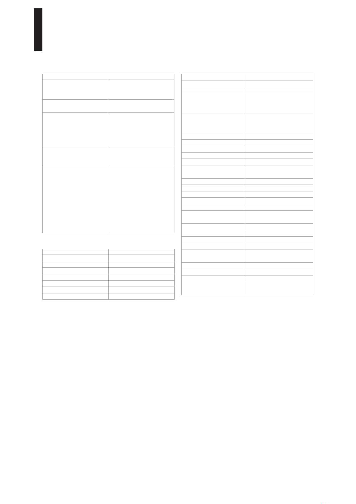
Technical data
Operating principle Microwave module
Detection speed Min. 0.1 m/s
Approvals CE
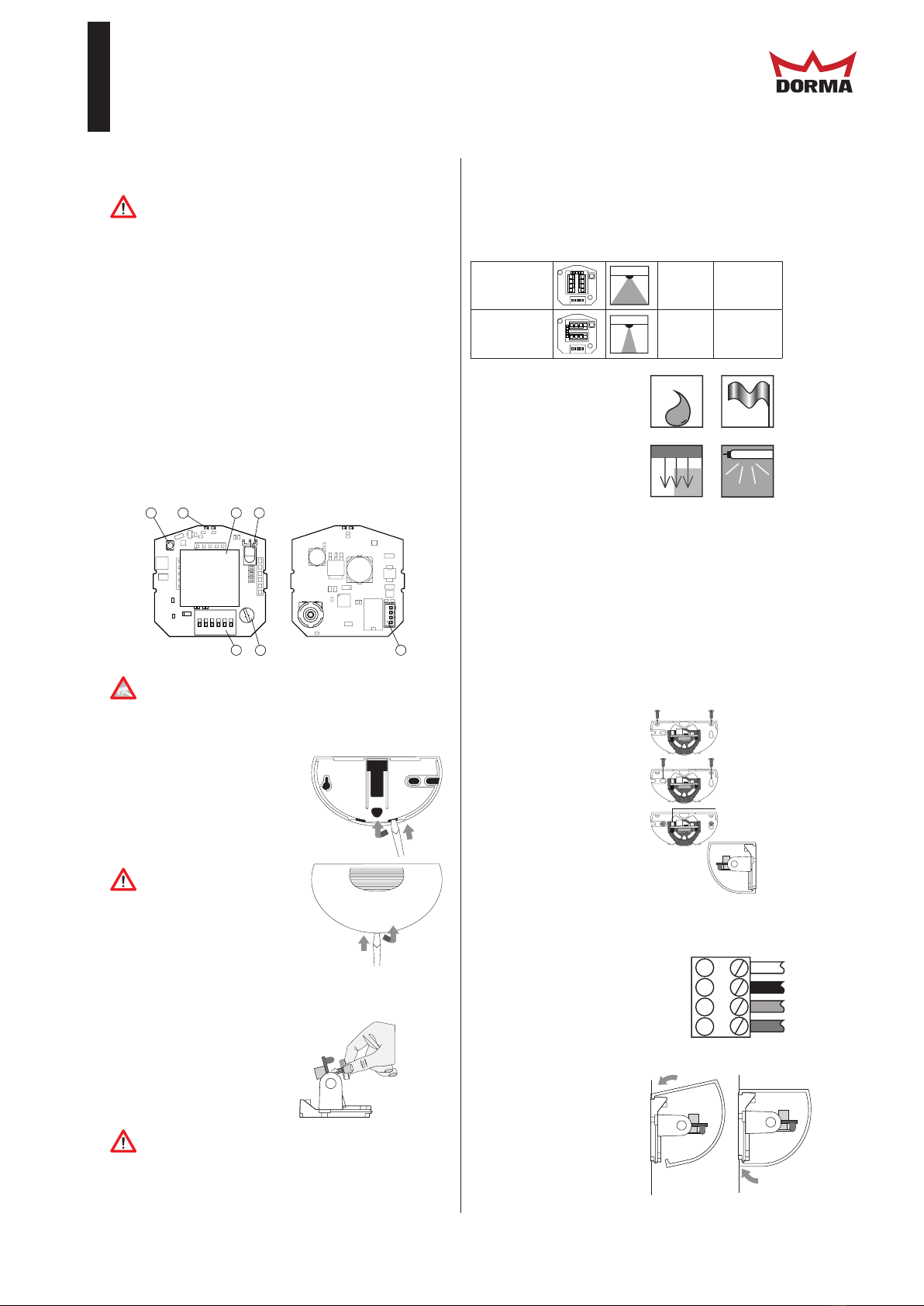
Detection field angle
vertical
horizontal
0 .. 90° in 5° increments
± 30° in 2.5° increments
Detection range at
installation height of 2200
mm and 30° angle:
(W x D)
Narrow: 2000 x 4500 mm
Wide: 4500 x 2000 mm
Operating frequency 24.15 ... 24.25 GHz, K band
Status display Red/green LED
Operating controls Potentiometer and DIP switch
Operating voltage 12 - 36 V DC/12 - 28 V AC
No-load current < 50 mA at 24 V DC
Power consumption < 1.2 W at 24 V DC,
< 1.7 W at 36 V DC
Operation mode Active/passive
Signal output Relay: 1 NO/NC
Switching voltage Max. 48 V AC/48 V DC
Switching current Max. 0.5 A AC/1 A DC
Switching power Max. 24 W/ 60 VA
Off-delay time (output) off, 0.2 s - 5 s, adjustable
(default setting 1 s)
Ambient temperature -20 °C to 60 °C
Relative humidity Max. 90 %, not condensing
Mounting height Max. 4000 mm
Class of protection IP 54
Connection Plug, 4-pin (connector cable
included with delivery)
Housing material Polycarbonate (PC), ABS
Weight 130 g
Transmitting power < 20 dBm EIRP
Dimensions without rain
protection cover (W x H x D)
123 mm x 65 mm x 57 mm
Troubleshooting
Fault Corrective action
Door is detected. Reduce the detection area
size.
Adjust the inclination angle.
LED not lit up. No power supply.
Device defective.
Sensor responds to very
slight interference such as
rain, vibration, reflections.
Door opens for no apparent
reason.
Increase immunity.
Reduce the detection area
size.
Potentiometer does
not respond.
Operation by remote control
is activated. Push DIP switch
6 UP (ON).
Remote control does
not respond.
Operation with DIP switch
and potentiometer is set.
Push DIP switch 6 DOWN.
Device is disabled (OFF).
Switch the operating voltage
off and on again. Sensor can
be configured for 30 minutes
without code.
Check the remote control
battery.
Original settings
Function Setting
DIP switches Switch 1-5: top, 6: bottom
Detection field angle 15°
Direction of detection Forward
Off-delay time (output) 1 s
Relay contact Active
Immunity 1
Slow Motion Off