DORMA AUTOMATICES, Inc. 924 Sherwood Drive Toll-Free: 877-367-6211 Subject to change without notice
DL3463-050 08/2016 Lake Bluff, IL 60044 Fax: 847-249-3999
ED100 / ED250 SERVICE MANUAL
—
9
6 Maintenance
A. Safety checks and inspection
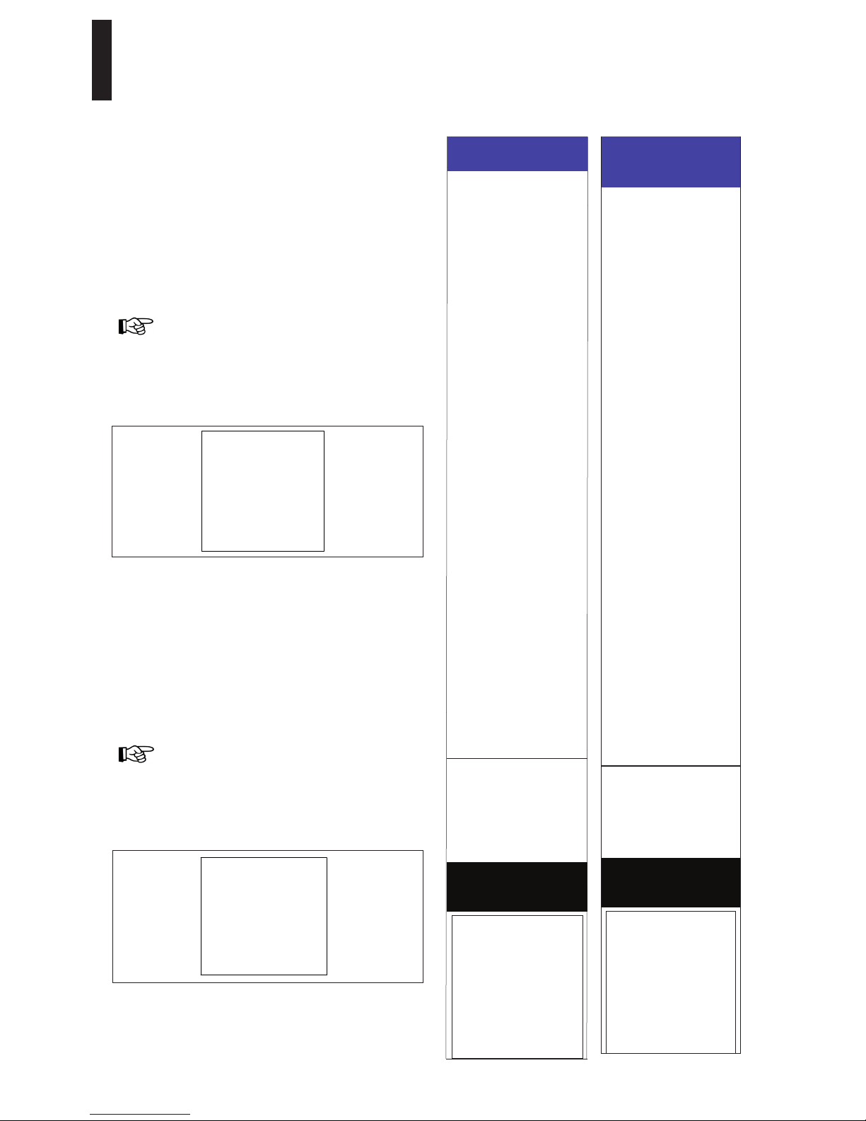
Safety information label – Automatic Swinging Doors
This AAADM label outlines safety checks that should be
performed daily on automatic swinging door controlled by
ED100 / ED250 operator.
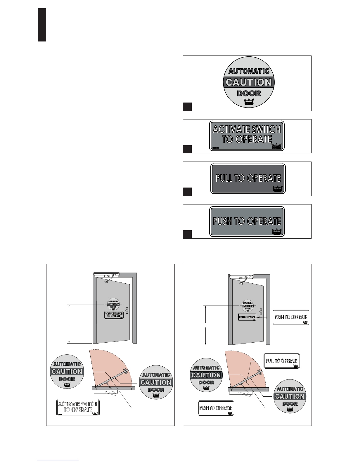
Safety information label – location
Place label in a protected, visible location on door frame, near
operator power switch if possible.
Annual Compliance Inspection section of label
This section of label is only completed on swing doors
that comply with ANSI/BHMA A156.10 standard and
pass inspection.
Additional annual compliance inspection labels
Place additional labels directly over Annual Compliance
Inspection section on Safety Information label.
Safety information label – Low Energy Swinging Doors
Label outlines safety checks that should be performed daily
low energy swinging door controlled by ED100 / ED250 door
operator.
Safety information label – location
Place label in a protected, visible location on door frame, near
operator power switch if possible.
Annual Compliance Inspection section of label
Section only filled out on low energy swing doors that
comply with ANSI/BHMA A156.19 standard and pass
inspection.
Additional Annual Compliance Inspection labels
Place additional labels directly over Annual Compliance
Inspection section on Safety Information label.
SAFETY INFORMATION
Automatic Swinging Doors
. Walk toward the door at a
normal pace. The door
should open when you ar
about 4 feet from the door.
. Stand motionless on
threshold for at least 10
seconds. The door shoul
not close.
. Move clear of the area. Th
door should remain open for
at least 1.5 seconds and
should close slowly and
smoothly.
. Repeat steps1 through 3
from other direction if door
is used for two way traffic.
. Inspect the floor area. It
should be clean with no
loose parts that might caus
user to trip or fall. Keep
traffic path clear.
. Inspect door's overall
condition. The appropriat
signage should be present.
. Have door inspected by a
AAADM certified inspecto
at least annually.
AAADM
American Association of Automatic
Door Manufacturers
ANNUAL COMPLIANCE
INSPECTION
INSPECT FOR AND
COMPLIES WITH ANSI
A156.10 ON:
DATE:______________
by AAADM Certified
Insepector
Number:___________
AAADM-2496
DO NOT USE DOOR if it fails
any of these safety checks of if
it malfunctions in any way. Call
a qualified automatic door
service company to have door
repaired or serviced.
See Owner’s manual or
instructions for details on
each of these and other
safety items. If you need
a copy of the manual,
contact the manufacturer.
These minimum safety checks,
in addition to those in the
Owner’s Manual, should be
made each day and after any
loss of electrical power.
SAFETY INFORMATION
Low Energy Swinging
Doors
. Activate the door. Door
should open at a slow
smooth pace (4 or more
seconds), and stop withou
impact.
. Door must remain fully open
for a minimum of 5 seconds
before beginning to close.
. Door should close at a slow,
smooth pace (4 or more
seconds), and stop without
impact.
. Inspect the floor area. It
should be clean with no
loose parts that might cause
user to trip or fall. Keep
traffic path clear.
. Inspect door‘s overall
condition. The appropriate
signage should be present
and the hardware should
be in good condition.
. Have door inspected by an
AAADM certified inspector
at least annually.
AAADM
American Association of Automatic
Door Manufacturers
ANNUAL COMPLIANCE
INSPECTION
INSPECT FOR AND
COMPLIES WITH ANSI
A156.19 ON:
DATE:______________
by AAADM Certified
Insepector
Number:___________
AAADM-3044
DO NOT USE DOOR if it fails
any of these safety checks of if
it malfunctions in any way. Call
a qualified automatic door
service company to have door
repaired or serviced.
See Owner’s manual or
instructions for details on
each of these and other
safety items. If you need
a copy of the manual,
contact the manufacturer.
These minimum safety checks,
in addition to those in the
Owner’s Manual, should be
made each day and after any
loss of electrical power.
ANNUAL COMPLIANCE
INSPECTION
INSPECT FOR AND
COMPLIES WITH ANSI
A156.10 ON:
DATE: _____________
by AAADM Certified
Inspector
Number: ____________
ANNUAL COMPLIANCE
INSPECTION
INSPECT FOR AND
COMPLIES WITH ANSI
A156.19 ON:
DATE: ______________
by AAADM Certified
Inspector
Number: ___________