Dorma KTC-2 Technical manual

Stand 08.02.2012 Technische Änderungen vorbehalten
Software-Update_Ver1010_GB.doc DORMA KT-Systeme Seite 1 von 14
KTC-2 (MS9)
Software-Update Version 1.0.10 manual
In order to keep your door systems updated, please proceed with the following
changes.
1. Exchange CPU -Z1 (E60-0228-10) by the new one you already received.
Front view
Relay K3-K7 Terminal block –X101/-X100
Microcell Three control
unit
(N60-0685)
Module for locking device
(E60-0120)
Output module
(E60-0119)
Input module
(E60-0118)
CPU –Z1 (E60-0228-10)

Stand 08.02.2012 Technische Änderungen vorbehalten
Software-Update_Ver1010_GB.doc DORMA KT-Systeme Seite 2 von 14
KTC-2 (MS9)
Rear view
Frequency converter
(N60-0402)
Mains filter (N60-0405)
Mains connection
230 V AC –X103
24 V DC power supply unit
(N60-0583)
Relay K1
(N60-0560)
Service power outlet
max. 300 W
(N60-0694)
Collector (230VAC)-X105
Potentiometer for
24V DC adjustment
Readout the parameter settings before exchanging, in order to transfer these to the
new CPU.

Stand 08.02.2012 Technische Änderungen vorbehalten
Software-Update_Ver1010_GB.doc DORMA KT-Systeme Seite 3 von 14
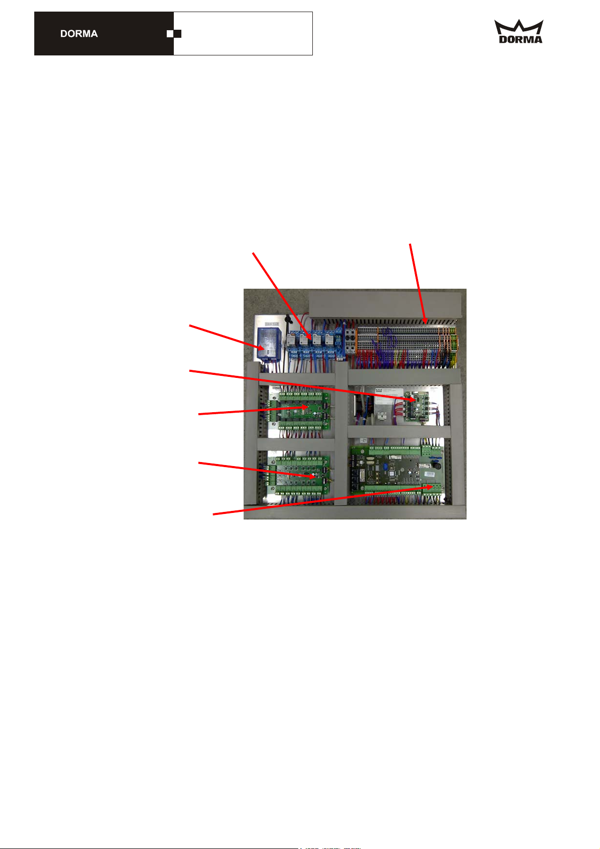
KTC-2 (MS9)
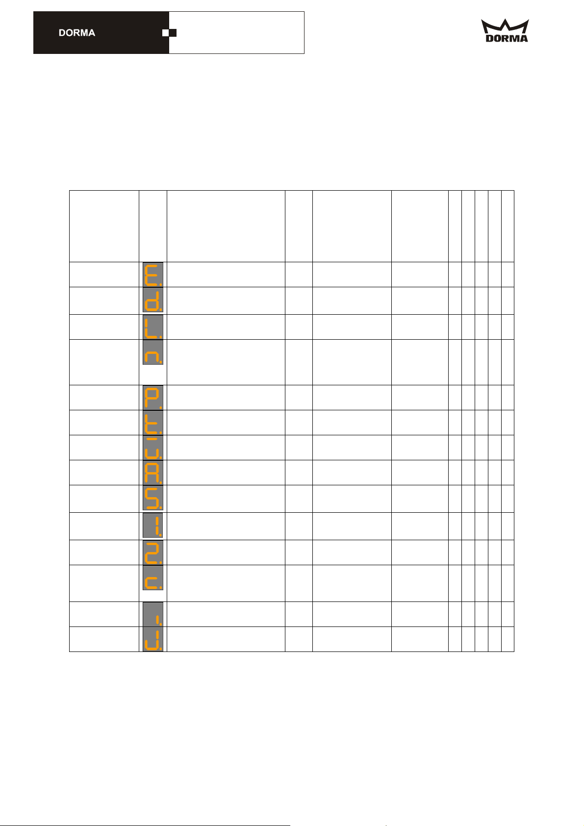
The following chart shows the setting entries:
The standard values are shown here, they may however vary.
Parameters
Parameter
designation
Symbo
l
Description Unit Range Original
setting
Palm
Central system
Learning cycle
Original setting
Wiring
Current error
status
Error list - - - - -
Door diameter
Door diameter mm 2000 .. 6500 (system
learns
diameter)
- - C - -
#el. locking
devices
Electromechanical bolt locking
device no = 0, yes = 1
0 .. 1 0 U U - C -
Hold after stop
Time until the el. brake is
released after an Emergency
Stop
0 = brake never released, 1 - 9
= after... sec.
sec (0 .. 9) sec 1 U U - C -
#X-Pos Auto
1 - 2
Number of starting positions in
Automatic 1 or 2
2 .. 5 2 U U - C -
SlowStop canopy
SlowStop time of canopy-
integrated sensors
sec (0 .. 15) sec
16 = ∞16 U U - C -
SlowStop wing
SlowStop time of wing sensor 0.1
sec
(0 .. 15.9) sec
16.0 = ∞16.0 U U - C -
Hold after stop
Time until the door starts after a
safety stop
0.1
sec
(0 .. 9.9) sec 1.0 U U - C -
Sec. area stop
Detection range of canopy-
integrated sensor in security
area for SlowStop
mm (d * (pi/3)
.. 500) mm 700 U U - C -
Summer
configuration
Starting-positions: 0°/180° (system
reads X-
positions)
- - - - U
Starting position
Summer
Starting-positions: 90°/270° [0],
60°/240° [1]
0 .. 1 0 U U - C -
PosV after safety
stop
Time system operates in
positioning speed after leaving
the stationary position following
a safety stop
0.1
sec
(0.0 .. 2.9) sec 1.0 U U - C -
A/M lighting
Automatic/manual lighting
control
0 ... 1 0 (auto) U U - C -
FUT warm air
curtain
Follow-up time of warm air
curtain
sec 0 ... 600 10 U U - C -
Caption:
U = adjustable value
C = resettable value
- = non-adjustable value

Stand 08.02.2012 Technische Änderungen vorbehalten
Software-Update_Ver1010_GB.doc DORMA KT-Systeme Seite 4 von 14
KTC-2 (MS9)
-Z1
2. Reconnect NC at OUT4 to NO at the locking module „IL1“.
OLD:

Stand 08.02.2012 Technische Änderungen vorbehalten
Software-Update_Ver1010_GB.doc DORMA KT-Systeme Seite 5 von 14
KTC-2 (MS9)
-Z1
NEW:

Stand 08.02.2012 Technische Änderungen vorbehalten
Software-Update_Ver1010_GB.doc DORMA KT-Systeme Seite 6 von 14
KTC-2 (MS9)
3. Please check if terminals X101:59 and 60 are connected to -IL1(see picture).
For doors with integrated sliding doors bridge –X101:+ with 60, please!
- +

Stand 08.02.2012 Technische Änderungen vorbehalten
Software-Update_Ver1010_GB.doc DORMA KT-Systeme Seite 7 von 14
KTC-2 (MS9)
4. Change the following in the UPS monitoring circuit:
- New terminal strips –X105
- Additional relay K7 (230VAC-version)
Exchange the old terminal strip –X105 by the new one and install the additional relay
K7. Wiring as follows:
NEW “K7”

Stand 08.02.2012 Technische Änderungen vorbehalten
Software-Update_Ver1010_GB.doc DORMA KT-Systeme Seite 8 von 14
KTC-2 (MS9)

Stand 08.02.2012 Technische Änderungen vorbehalten
Software-Update_Ver1010_GB.doc DORMA KT-Systeme Seite 9 von 14
KTC-2 (MS9)
5. Carry out the wiring as follows if the door system is furnished with UPS:
If a UPS is joined up in circuit, put the inlet connector for non-heating apparatus from
–X103 into the UPS and the other 230VAC adapter cable to be connected between
UPS and control system at –X103.

Stand 08.02.2012 Technische Änderungen vorbehalten
Software-Update_Ver1010_GB.doc DORMA KT-Systeme Seite 10 von 14
KTC-2 (MS9)
6. Is the door system without UPS, please proceed with the wiring as follows:

Stand 08.02.2012 Technische Änderungen vorbehalten
Software-Update_Ver1010_GB.doc DORMA KT-Systeme Seite 11 von 14
KTC-2 (MS9)
+
-
7. Re-wire the inputs in the rotating part „I1“ here IN10+11 as follows:

Stand 08.02.2012 Technische Änderungen vorbehalten
Software-Update_Ver1010_GB.doc DORMA KT-Systeme Seite 12 von 14
KTC-2 (MS9)
8. Adjust the crossover cable from the MS9 control system to ES200.
Connect the delivered 2-wire cable „33.1 ES200-Not Halt“ with the terminals –
X101:33/34 and ES200:32/33. Remove bridge (ES200: 32-33) at ES200 beforehand.
New connection Terminal “47” is connected to
+24VDC

Stand 08.02.2012 Technische Änderungen vorbehalten
Software-Update_Ver1010_GB.doc DORMA KT-Systeme Seite 13 von 14
KTC-2 (MS9)
9. Change of emergency-stop logic. The ES200 drive will be stopped by
emergency-stop when activated.
The auxiliary contactor N60-0460 must be put on „K1“ contactor.
Normally open K1:53 and 54 to be connected to the terminals –X101:33 and 34 as
follows:
ES200
-X101

Stand 08.02.2012 Technische Änderungen vorbehalten
Software-Update_Ver1010_GB.doc DORMA KT-Systeme Seite 14 von 14
KTC-2 (MS9)
If all changes are carried out, please put the door system back into operation as
follows:
10. Initial operation of the door system
The emergency-stop is activated
The control system is switched on
Program switch KT on Automatic 1
The curved sliding door wings and the showcase doors are closed
The frequency converter and the CPU are parameterized
Door system is in summer position
Push Select push button and keep it pushed for 4 sec
Release emergency-stop
Learning cycle starts
Indication of learning cycle and positioning drive
During the learning cycle and positioning drive the display shows a gyro.
Door system rotates in positioning speed
The door system turns for min. 1 rotation
Afterwards the door system restarts with its regular function
Check all functions according to the original manual and/or the attached chart.
Check if the control system has learned the correct diameter. Check via parameter .
11. Testing of changes
- Door systems with UPS: Revolving door has to rotate in program switch position
Auto1 or Auto2 into summer position and stop there.
- Program switch position in „Summer“ and the sliding door is in operation (test all
program switch positions of the sliding door), sliding door must stop in case the
emergency-stop is activated and remain in this position as long as this is
activated.
- Check all revolving door functions again.
Done
This manual suits for next models
1
Popular Industrial Equipment manuals by other brands

ABB
ABB REF601 CEI User manual and technical description

Elkay
Elkay Flexi-Guard EZ Series Care & use manual

Siemens
Siemens MOBILETT Plus Service instructions

Asset construction hire
Asset construction hire Atlas Copco LT 6005 Basic instructions

Orion
Orion 24555 user manual

Nibco
Nibco PEX Plumbing Installation Manual