manuals.online logo
Brands
  1. Home
  2. •
  3. Brands
  4. •
  5. dosatron
  6. •
  7. Plumbing Product
  8. •
  9. dosatron D14MZ10 User manual

dosatron D14MZ10 User manual

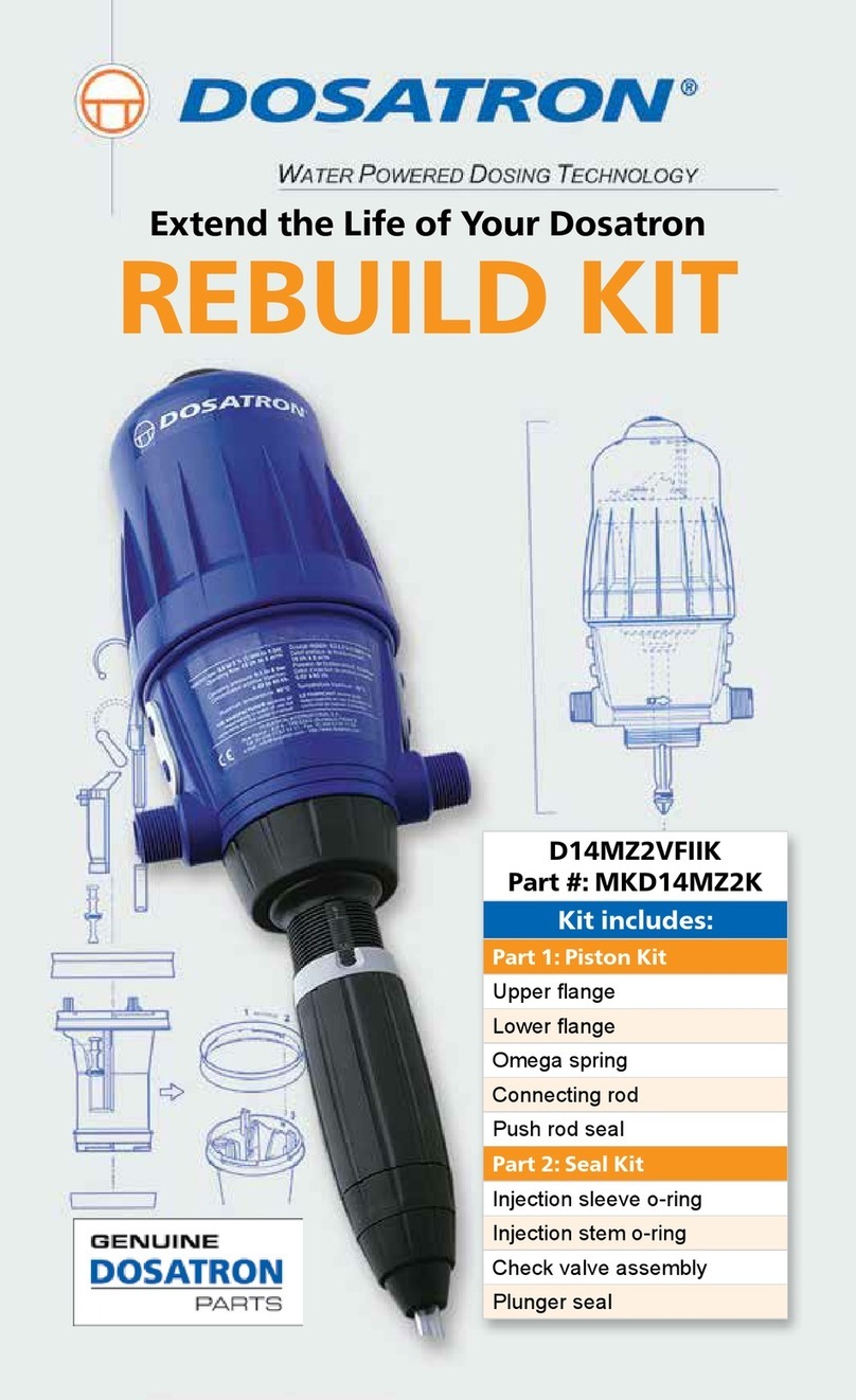
Extend the Life of Your Dosatron
REBUILD KIT
D14MZ10
CHAT at www.dosatronusa.com
This kit is for the Dosatron D14MZ10 and consists of two parts:
Congratulations on purchasing
your Dosatron Rebuild Kit.
Part #: MKD14MZ10AF • MKD14MZ10VF
MKD14MZ10VVF •MKD14MZ10VAF
• Part 1 - Piston Kit
Part 2 - Seal Kit Contents:
PJDI118 - Check Valve Assembly
(VF and AF)
PJDI118V - Check Valve Assembly
(VVF and VAF)
JDI122 - Injection Stem O-Ring
JDI100 - Injection Sleeve O-Ring
JDI123 - Plunger Seal
• Part 2 - Seal Kit
Remember to wear proper protection when performing maintenance
such as gloves, eyewear, and apron.
Part 1 - Piston Kit Contents:
PDI651 - Omega Spring
PDI649 - Connecting Rod
PDI648 - Push Rod Seal
PDI643 - Upper Flange
PDI644 - Lower Flange
1-800-523-8499 • 1-727-443-5404
D14MZ10
Part 1: Piston Kit Instructions
Begin by removing the piston
from your Dosatron injector.
Unscrew and remove the bell
housing (you may use a
universal strap wrench), pulling
the piston out of the body. Set
the bell housing and body aside.
Remove the plunger by twisting
a quarter turn counter clockwise
and set aside.
In order to remove the top or
larger diameter ange, locate the
small notch inside the black
piston shell. This is where a
tooth, on the inside of the
ange, locks it into place.
1
2
3
1
CHAT at www.dosatronusa.com
You will need to apply pressure
to the ange on either side of
the notch as you twist the ange
counter clockwise. It may be
a snug t. Lift to remove and
discard.
Flip the piston upside down
and follow steps 3 and 4 to
remove the lower or smaller
diameter ange.
To remove the motor and valve
support assembly from the piston
shell, you will need a at head
screwdriver. Using the
screwdriver, remove the upper
valves from the guide. The
valves look like golf tees and
will drop down and out of the
piston shell. Set them aside.
4
5
6
2
1-800-523-8499 • 1-727-443-5404
Grasp the top of the white plastic
parts of the mechanism and lift
straight up.
You now have two
subassemblies – the push rod
on the left and the valve support
frame on the right.
In order to disassemble the push
rod, remove the connecting rod
off the Omega spring.
9
8
7
3
CHAT at www.dosatronusa.com
Twist to remove the Omega
spring out of the push rod.
Install the new Omega Spring
(Part #: PDI651) by carefully
pushing the Omega spring into
the push rod.
Slide the other end of the Omega
spring into the new Connecting
Rod (Part #: PDI649). The key
to this step is to make sure the
curved top of the push rod faces
in the same direction as the
Omega spring.
Replace the Push Rod Seal
(Part #: PDI648). Remove by
grasping and turning counter
clockwise. Carefully slide the
new push rod seal onto the
push rod as far as it will go and
twist a quarter turn clockwise
to lock.
10
11
12
4
1-800-523-8499 • 1-727-443-5404
Install the new Upper Flange
(Part #: PDI643) by locating the
small tooth on the inner diameter
of the ange.
Now locate the notch on the
piston shell.
Be careful not to install the
ange upside down.
14
13
15
5
CHAT at www.dosatronusa.com
Align the tooth with the shell and
press down and twist a quarter
turn clockwise to lock. If it is
difcult to twist or if the ange
lifts up easily, just remove the
ange, realign and try again.
Install the new Lower Flange
(Part #: PDI644) the same way.
Before reinstalling the push rod
and valve support assembly, look
inside the piston shell. You will
notice four holes in a line and a
single hole on the other side.
16
17
18
6
1-800-523-8499 • 1-727-443-5404
Notice how the valve support
frame aligns on the side with the
four holes, making sure it goes
into the grooves.
To demonstrate the alignment
of the push rod assembly, the
curved top would face inward,
inserting the push rod into the
single hole. This is where
the connecting rod sits in
the piston.
The key is to make sure the
white connecting rod drops
into the notches inside the
piston shell.
20
19
21
7
CHAT at www.dosatronusa.com
Now to insert both the valve
support frame and the push rod
into the piston shell, use your
index nger to push on the
spring. This will set everything
into place and you will hear
a click. If the parts aren’t
tting together, just lift both
subassemblies out and try again.
Insert the upper valves into the
bottom of the upper area,
snapping them into the valve
support frame.
To test the piston pull the push
rod up and press it down a few
times. It should click in both
directions.
22
23
24
8
1-800-523-8499 • 1-727-443-5404
Reinstall the plunger into the
bottom of the piston shell and
twist a quarter turn clockwise
to lock.
Carefully press the piston back
into the injector and install the
bell housing.
25
26
For video instructions go to: http://www.dosatronusa.com/
d14mz10/ and view the D14MZ10 Troubleshooting Video and the
D14MZ10 Piston Video or scan the QR codes below with your
smart phone.
If you have any questions, call 800-523-8449 or to CHAT visit
www.dosatronusa.com.
D14MZ10 Piston Video D14MZ10 Troubleshooting Video
9
CHAT at www.dosatronusa.com
D14MZ10
Part 2: Seal Kit Instructions
PJDI122/PJDI122V
Unscrew the suction hose nut
and remove the suction hose.
Unscrew the injection stem nut.
Pull the injection stem straight
out from the body of the injector.
Set the body aside.
1
2
3
10
1-800-523-8499 • 1-727-443-5404
Unscrew and remove the check
valve nut.
Grab the barb and pull the
check valve assembly straight
out and discard.
Unscrew and remove the
lock nut.
4
5
6
11
CHAT at www.dosatronusa.com
Remove the C clamp by
spreading the opening and
sliding it down over the threads.
Unscrew and remove the
adjusting nut. Slide the injection
stem nut off.
Push the white injection stem up
and out of the black sleeve.
9
8
7
12
1-800-523-8499 • 1-727-443-5404
Remove and replace the
Injection Stem O-Ring
(Part #: JDI122).
Remove and replace the
Sleeve O-Ring (Part #: JDI100).
Align the tooth inside the lower
portion of the black sleeve with
the groove in the white stem.
Sliding the stem down in, as far
as possible.
10
11
12
13
CHAT at www.dosatronusa.com
Slide the injection stem nut
up onto the sleeve, and thread
the adjusting nut back on.
Replace the C clamp by sliding
it over the threads. Rotate until it
clicks into place.
Thread on the lock nut and
hand tighten.
14
13
15
14
1-800-523-8499 • 1-727-443-5404
Install the new Check Valve
Assembly into the stem.
NOTE: Part #: PJDI118 for
D14MZ10VF and D14MZ10AF.
Part #: PJDI118V for
D14MZ10VAF and
D14MZ10VVF.
Reinstall the check valve nut.
Set the stem aside and pick up
the blue body. Using a small at
head screwdriver, remove the
Plunger Seal (Part #: JDI123).
Install the new plunger seal into
the groove on the plunger.
16
17
18
15
CHAT at www.dosatronusa.com
Align the notches in the lower
part of the blue body with the
teeth on the top of the injection
stem assembly.
Reinstall the nut hand tight.
If the scale you prefer is not
facing out, just loosen the stem
nut and remove.
Pull the stem down slightly,
rotate 180 degrees and push it
back up.
20
19
21
16
1-800-523-8499 • 1-727-443-5404
Reinstall the nut hand tight.
Before installing the suction
hose, inspect it. If it ares out,
cut an inch or so off and reinstall.
If the suction hose is cracked,
rigid, or looks really old, just
replace it.
Thread the suction hose nut
onto the hose. Slide the hose
onto the barb. Reattach the
hose nut.
22
23
24
For video instructions go to:
https://www.youtube.com/user/DosatronIntl
and view the D14MZ10 Service Video or
scan the QR code with your smart phone.
D14MZ10
Service Video
CHAT at www.dosatronusa.com
2090 Sunnydale Blvd. • Clearwater, FL 33765
1-800-523-8499 • www.dosatronusa.com

Other manuals for D14MZ10

1

This manual suits for next models

4

Other dosatron Plumbing Product manuals

dosatron D9 Green Line Operator's manual

dosatron

dosatron D9 Green Line Operator's manual

dosatron D14MZ2VFIIK User manual

dosatron

dosatron D14MZ2VFIIK User manual

Popular Plumbing Product manuals by other brands

Hans Grohe Push open 50100 Series Assembly instructions

Hans Grohe

Hans Grohe Push open 50100 Series Assembly instructions

Wirquin PRO COMPACT + Assembly instructions

Wirquin PRO

Wirquin PRO COMPACT + Assembly instructions

baliv 70 Series manual

baliv

baliv 70 Series manual

Glacier bay HD67877W-6001 Installation and care guide

Glacier bay

Glacier bay HD67877W-6001 Installation and care guide

METHVEN MINIMALIST MMSCP installation guide

METHVEN

METHVEN MINIMALIST MMSCP installation guide

Hans Grohe Massaud Tumbler 42234000 Dimensions

Hans Grohe

Hans Grohe Massaud Tumbler 42234000 Dimensions

Graff ME25 2329500 installation instructions

Graff

Graff ME25 2329500 installation instructions

Kohler K-10481 installation guide

Kohler

Kohler K-10481 installation guide

Hans Grohe Axor 39134000 Instructions for use/assembly instructions

Hans Grohe

Hans Grohe Axor 39134000 Instructions for use/assembly instructions

Waterstone 1100 installation instructions

Waterstone

Waterstone 1100 installation instructions

Water Factory Systems FaucetMATE owner's manual

Water Factory Systems

Water Factory Systems FaucetMATE owner's manual

Hans Grohe AXOR Uno 45113 1 Series Installation/User Instructions/Warranty

Hans Grohe

Hans Grohe AXOR Uno 45113 1 Series Installation/User Instructions/Warranty

Harvia sentiotec Komfort Small Instructions for installation

Harvia

Harvia sentiotec Komfort Small Instructions for installation

Hans Grohe Focus E 31700 Series Assembly instructions

Hans Grohe

Hans Grohe Focus E 31700 Series Assembly instructions

Zip HydroTap G4 Tap installation instructions

Zip

Zip HydroTap G4 Tap installation instructions

PEERLESS P240LF manual

PEERLESS

PEERLESS P240LF manual

Elkay Arezzo LK7420BC Specifications

Elkay

Elkay Arezzo LK7420BC Specifications

Tecma Silence Installation & use

Tecma

Tecma Silence Installation & use

manuals.online logo
manuals.online logoBrands
  • About & Mission
  • Contact us
  • Privacy Policy
  • Terms and Conditions

Copyright 2025 Manuals.Online. All Rights Reserved.