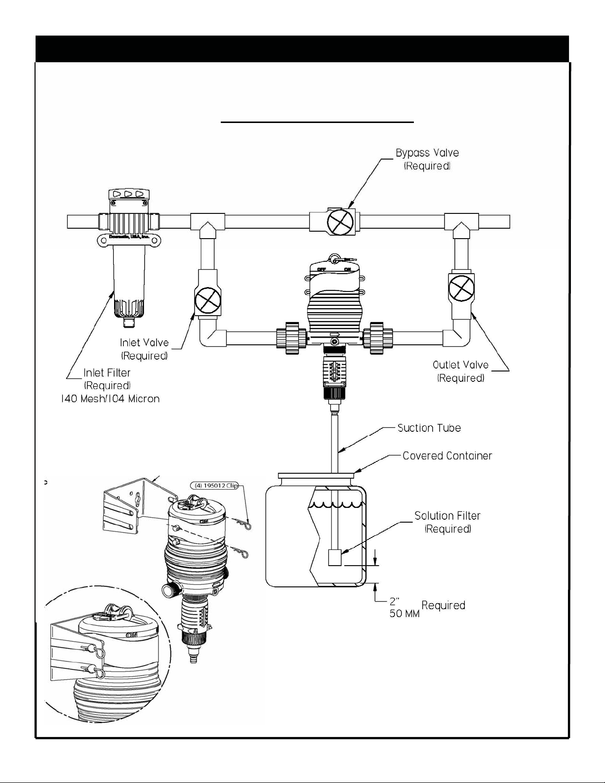
Dosmatic MINIDOS 10% Manual

Installation & Operating Instructions
Manuel d’Installation et d’Utilisation
Instrucciones para Instalacion y Operacion
Model No.
1.0 %
2.5 %
5.0 %
10.0 %
MiniDos
ISO 9001:2000 Quality Management System

CAUTION:
To reduce risk of injury, user
must read and understand the
Installation & Operating In-
structions before using this
product.
ITEM PAGE
Introduction…………….… 3
Safety…………………...... 4
Installation…………..... 5-7
Operation…………….... 8-9
Maintenance…………. 9-10
Trouble Shooting…..... 10-11
Specifications………..…. 12
Repair Parts Motor….…. 13
Repair Parts Lower… 14-17
Warranty….……………. 20
Locations……………….. 20
CONTENTS
2

INTRODUCTION PRESENTATION
Please take the time to read this in-
struction manual thoroughly and
follow the procedures. This will
help increase the life of your injec-
tor.
Certain precautions, which
are marked with this symbol:
need to be read carefully.
The injector is packaged with the
following items (as shown in figure
1):
Dosmatic injector (not shown)
Dosage piston (A)
O-ring (B)
Manual (not shown)
Mounting bracket (C )
Mounting clips (D)
Filter (F)
Suction Tube (G)
Certaines précautions, qui
sontsignalées par ce sybole:
ont besoin d’être luestrès atten-
tivement.
Veuillez prendre le temps de lire
entièrement ce manuel d’instruction
et de suivre les procédures. Ceci
vous aidera à augmenter la durée de
vie de votre doseur.
Nous conditionnons l’injecteur avec
lescomposants suivants (comme
représentésur le schéma 1):
L’injecteur DOSMATIC (non
représenté)
Piston doseur (A)
Joint (B)
Manuel (non représenté)
Support de fixation (E)
Epingle de fixation (D)
Tige de commande (E)
Filter (F)
Suction Tube (G)
PARTS PACKAGED WITH INJECTOR
Fig. 1
Lea detenidamente este manual
de instrucciones y siga sus ins-
trucciones. Esto le ayudará a pro-
longar la vida de su dosificador.
Preste especial atención a
las recomendaciones señaladas
con este símbolo:
El inyector se entrega con los si-
guientes componentes (como se
representa en el
esquema 1):
- Inyector Dosmatic (no
representado).
- Pistón Dosificador (A)
- Junta (B)
- Manual (no representado)
- Soporte de montaje (E)
- Horquilla de fijación (D)
-Filtro (F)
- Tubería (G)
A
B
C
F&G
D
Dosage pistons ranging from 1% - 10%
3

4
1. SELECT A LOCATION: That
is on the water line that chemi-
cal injection is desired and
meets all the following require-
ments as well as all applicable
local codes:
2. Remove Red Caps Prior to
installation.
NOTE: The entire water line down
stream from the injector will have
chemical injected into it. If the
chemical injected makes the water
unsafe to drink label the water
lines.
2. AN APPROVED BACK
FLOW PREVENTOR MUST BE
INSTALLED:In the water line
ahead of the unit to prevent water
and chemical mixture from entering
the source water supply.
3. AVOID A POTENTIALLY
HAZARDOUS CHEMICAL
ACCIDENTS: An injector loca-
tion should be selected to provide
a safe, but accessible, place for the
chemical solution container. It
should be kept away from children
and/or high usage areas.
4. AVOID SOLUTION CON-
TAMINATION, use only clean
FILTERED water. Do not allow
contaminants to enter the solution
container because they will be
pumped into the water line, can
cause the spread of disease and
can also cause excessive wear.
5. WATER TEMPERATURE:
Max: 100qF or 38qC
Min: 32qF or 0qC5.
6. MAX WATER PRESSURE:
100PSI / 6,9 BAR
7. RELEASE WATER PRES-
SURE: Before working on injector.
SAFETY
WARNING NOT FOR HUMAN
CONSUMPTION
ENDROIT
Choisissez un endroit qui répond à
toutes les conditions suivantes ainsi
qu’aux obligations locales :
1. Sur la ligne d’eau où l’injection
chimique est réalisée.
Note : La conduite d’eau à partir
de l’injecteur contiendra le produit
chimique injecté.
Si le produit chimique injecté rend
l’eau impropre à la consommation,
les conduites d’eau devront être éti-
quetés :
ATTENTION EAU NON
POTABLE
2 PREVENTION : UN DISCON-
NECTEUR , CLAPET ANTI RE-
TOUR, NORMALISE DOIT
ETRE INSTALLE OBLIGATOI-
REMENT,dans le circuit hydrauli-
que en amont de l’injecteur pour
LUGAR
Elija un lugar que responda a todas las
condiciones siguientes así como a las
normativas locales:
En la conducción hidráulica donde se
realiza la inyección química.
Nota: La conducción de agua a
partir del inyector contendrá el
producto químico inyectado.
Si la solución a inyectar provoca la
inaptitud del agua para el consumo,
todas las conducciones deben llevar un
distintivo como el que sigue:
¡ ATENCIÓN!
¡AGUA NO POTABLE!
2. PREVENCIÓN: SE DEBE
INSTALAR OBLIGATORIA-
MENTE UN
DESCONECTOR NORMALI-
ZADO en el circuito hidráulico, em-
plazado antes del
inyector para evitar el acceso a la red
principal de los productos químicos.
3 PARA EVITAR RIESGOS DE
ACCIDENTE QUÍMICO:
Ubique el contenedor de solución en
un lugar alto pero accesible. Debe estar
fuera del alcance de los niños y de zo-
nas de tránsito frecuente. Además, el
emplazamiento elegido para la instala-
ción debe estar libre de riesgos de hela-
das.
4 PARA EVITAR LA CONTAMI-
NACIÓN DE LA SOLUCIÓN:
Utilice únicamente agua limpia. Prote-
ja el contenedor de la solución para
evitar la intrusión eventual de contami-
nantes, ya que éstos serían bombeados
e integrados en el circuito hidráulico y
podrían provocar la propagación de
enfermedades. La suciedad y otras im-
purezas en el
interior del depósito de disolución pue-
den provocar un desgaste prematuro
del inyector.
5. TEMPERATURA DEL AGUA
Máx : 38°C
Mín : 0°C
3. POUR ÉVITER TOUT RISQUE
D’ACCIDENT CHIMIQUE
Placer le réservoir de solution chimique
à injecter dans un endroit sûr mais ac-
cessible.Il doit être hors de portée des
enfants et des passages fréquents, l’em-
placement de l’installation ne devra
également pas être soumis aux risques
de gel.
4. POUR ÉVITER TOUTE CONTA-
MINATION DE LA SOLUTION,
n’utiliser que de l’eau claire et FIL-
TREE. Protéger le bac de solution pour
éviter l’intrusion éventuelle de contami-
nants, en effet, ils seraient pompés et
intégrés dans le circuit hydraulique et
pourraient causer la propagation de ma-
ladies.
La saleté, les débris et autres impuretés
dans le bac peuvent aussi causer une
usure prématuré de l’appareil.
5. TEMPERATURE DE L’EAU
Max : 38°C
Min : 0°C

5
SEE FIG 2
1. NOTE: Water going through in-
jector must be free of sand, dirt and
grit. Installation of 140 mesh (104
micron) or finer filter will be re-
quired.
2. MOUNT INJECTOR: Securely
to a solid object such as a wall.
Note arrow on injector indicating
water flow. See fig. 3
3. BACKFLOW PREVENTOR:
Install an adequately sized that
meets your local code requirements.
4.BYPASS VALVING: To by-
pass injector when not in service or
to service injector pipe in the three
valve bypass arrangement as shown
in Fig. 2. Valves (A) (B) & (C ).
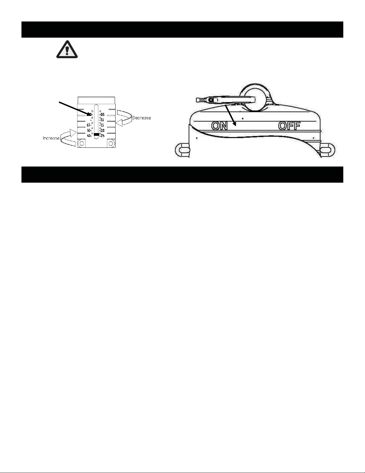
5. CHECK SYSTEM FOR
LEAKS: Open the bypass valve
(A) close valves (B) and (C ) so that
the water will not flow into injector.
Slowly turn on the main water line
so that water will run through the
plumbing system. Turn on all of the
valves located downstream from
your injector to release trapped air.
Slowly turn on the inlet valve (B).
Open the outlet valve (C ) at injec-
tor outlet. Close the bypass valve
(A). As water travels freely through
your injector, you will hear a soft
“clicking” sound.
6. SOLUTION CONTAINER:
Refer to figure 4. You may use any
size container, but we recommend
using one with a lid or cover. To
connect your solution container,
Gently push the end of the suction
tube (#25) onto the bottom of the
fitting assembly(#11). Place the fil-
ter into the solution container at
least 2 inches (5 CM) from the bot-
tom. Cover the solution filter with
at least 2 inches (5 CM) of chemi-
cal solution.
INSTALLATION
INSTALLATION
Voir Fig 2
1 NOTE : L’eau qui passe par l’in-
jecteur ne doit pas contenir de sa-
ble ou saleté. L’installation d’un
filtre de grille 104 μ est requise.
2 FIXER L’INJECTEUR sur un
support solide tel un mur. Faire at-
tention à la flèche sur le doseur qui
indique le sens de l’eau motrice. Voir
fig 3
3Installer un clapet anti-retour qui
répond aux normes locales.
4 MONTAGE EN DERIVATION :
pour dévier l’eau motrice lorsque la
pompe n’est pas en service vous pou-
vez installer la tuyauterie avec 3 val-
ves en by pass comme montré dans la
fig 2 Valves (A) (B) & (C).
5 VERIFIER SI LE SYSTEME
FUIT
Ouvrir la vanne (A), fermer les van-
nes (B) et (C), ainsi l’eau ne passe
pas par le doseur.
Lentement allumer la ligne d’eau
principale ainsi l’eau passera dans
l’ensemble du système.
Ouvrir toutes les vannes situées en
aval de votre injecteur pour chasser
l’air. Ouvrez lentement la vanne à
l’entrée du doseur (B). Ouvrez la
vanne (C) à la sortie de l'injecteur.
Fermez la vanne de dérivation (A).
L’eau circule librement par votre in-
jecteur puis vous entendez le
« click », bruit du fonctionnement.
6 BAC DE PRODUIT : Ref fig 4.
Vous pouvez utiliser toute taille de
bidon mais il est recommandé qu’il
ait un couvercle. Pour vous connecter
au bidon, pousser doucement l’em-
bout du tube d’aspiration (#25) dans
le l’embout d’aspiration (#11). Placer
le filtre dans le bidon au moins à 5cm
du fond du fût. Couvrir le filtre d’au
moins 5 cm de hauteur de solution
chimique.
INSTALACIÓN
1NOTA : el agua que abastece la
instalación no debe contener are-
na fina u otros abrasivos. Se debe
instalar necesariamente un filtro
de malla de 140 μ como mínimo.
2 FIJAR LA BOMBA en un so-
porte sólido como una pared.
Tener cuidado con la flecha sobre
el dosificador que indica el senti-
do del agua motriz. Ver fig. 3
3Instalar una válvula anti retor-
no.
4 MONTAJE EN BY PASS:
Esta instalación está recomenda-
da, ya que permite derivar la pre-
sión de agua del inyector mientras
se realiza el mantenimiento, insta-
lar tubería y 3 válvulas como lo
explica la Fig. 2 Válvula (A) (B)
& (C).
5 COMPROBAR SI EL SISTEMA
SE SALE : Abrir la válvula (a), ce-
rrar las válvulas (b) y (C), así el agua
no pasa por la bomba. Lentamente
abrir la línea de agua principal; así el
agua pasará por el circuito. Abrir
todas las válvulas situadas antes del
inyector para expulsar el aire. Abra
lentamente la válvula a la entrada del
dosificador (b). Abra la válvula (C) a
la salida del la bomba. Cierre la vál-
vula de derivación (a). El agua circu-
la libremente por la bomba luego se
oye el “click”, (ruido de funciona-
miento).
6CONTENEDOR DE PRODUC-
TO
Fig 4. Puede elegir el depósito de
producto de cualquier tamaño,
pero con una tapa
Coloque el tubo de aspiración (#25)
sobre la boquilla de aspiración (#11)
adaptada al inyector.
Instale la rejilla de filtrado en el ex-
tremo del tubo de aspiración. Intro-
dúzcalo todo a través de un agujero
perforado en la cubierta del contene-
dor de la solución, y llévelo hasta el
fondo dejando como mínimo 5 cm
entre el filtro y el fondo del depósito.
El depósito debe contener solución
suficiente para cubrir por lo menos el
filtro aproximadamente unos 5 cm.

INSTALLATION DWG.
Fig. 2
TYPICAL INSTALLATION
* Consult local code requirements for backflor prevention.
A
B
C
Fig. 3
6

OPERATION
SERVICE FLOW: Water drawn
down stream from the injector will
automatically cause the injector to
“click” and inject the set amount of
solution into the water line. The
higher the flow rate the more fre-
quent the clicking, as the injector is
designed to inject solution at the
same set ratio irregardless of water
flow.
Water flow and pressures
must be within the estab-
lished specifications. See
the specification section on
page 12 for your model.
CHANGE FEED RATE: The
feed rate on the injector is adjust-
able EVEN WHILE OPERATING AND
UNDER WATER PRESSURE. Rotate
the “Ratio Adjustment Sleeve” (61)
to change the solution injection ra-
tio. See fig 5 The setting indicator
mark in the sleeve opening indi-
cates the approximate ratio of injec-
tion setting. Check outlet water for
chemical to assure desired feed rate
is being delivered.
NOTE: Do not screw Ratio Ad-
juster below lowest setting line on
decal. This can cause the injector to
lock.
BYPASS OPERATION: Inject-
ing solution into the water line can
be TEMPORARILY stopped with
the bypass feature. Moving the
“Bypass Lever” to the “OFF” posi-
tion allows service water to pass
through the injector without inject-
ing chemical. With the Bypass
Lever set on the “ON” position the
injector will operate as normal and
“clicking” will be heard when water
is flowing. It is recommend to use
the three valve bypass valves in Fig
2 for continued bypassing or servic-
ing of the injector.
ACTION DU DEBIT : Le débit
d’eau motrice vers le doseur en-
traînera automatiquement le fonc-
tionnement de l’appareil qui
« cliquera » et injectera l’additif
dans la conduite d’eau.
Plus le débit est élevé
plus l’appareil « clique »
fréquemment, comme l’in-
jecteur est conçu pour injecter le
même taux quelque soit les varia-
tions de débit. Voir les spécificités
de votre appareil en p11.
CHANGEMENT DU TAUX
D’INJECTION
Le taux d’injection est réglable en
continu, MEME EN COURS DE
FONCTIONNEMENT et SOUS
PRESSION DE L’EAU. Pour
changer le taux d’injection tournez
« le cylindre d'ajustement » (61) .
Voir fig. 5 le repère de réglage
indique le taux de réglage de l’in-
jection.
N.B. : Ne pas dévisser la bague de
réglage au-delà de la graduation la
plus basse.
Vérifier à la sortie de la pompe que
le pourcentage désiré soit bien ob-
tenu.
UTILISATION DU BY PASS
L’injection de produit peut être
TEMPORAIREMENT interrompu
par l’équipement by pass de l’ap-
pareil. En basculant le commuta-
teur vers le « off » l’eau passe par
le doseur sans injection de produit.
En position « ON» on entend à
nouveau le « clic » l’appareil fonc-
tionne normalement grâce à l’eau
motrice. Pour une utilisation plus
durable en by pass il est recom-
mander de faire l’installation avec
3 vannes comme Fig2.
Attention : L'injecteur est sous
pression de l'eau indépendamment
de la position du commutateur ON/
OFF.
7
ACCIÓN DEL CAUDAL: El cau-
dal de agua motriz hacia la bomba
implica automáticamente el funcio-
namiento del la bomba que hace
“Clic” e inyectará el aditivo en el
circuito hidráulico.
Cuanto mayor es el caudal la bomba
hará más veces “clic”.
El inyector inyecta el mismo
% cualquiera que sea las va-
riaciones de caudal. Ver las caracte-
rísticas de su bomba en p11.
MODIFICACIÓN DEL POR-
CENTAJE DE INYECCIÓN
La tasa de inyección se puede regu-
lar mientras la bomba está en funcio-
namiento y bajo presión de agua.
Para cambiar el % de inyección en-
rosque o desenrosque el anillo de
reglaje (61) hasta alcanzar el reglaje
deseado. Alinear la parte superior
del anillo de reglaje hasta situarse
sobre el % de inyección deseada.
(ver esquema 5)
NOTA: No desenrosque el anillo de
reglaje más allá de la graduación
más baja. Compruebe a la salida del
inyector que la tasa de inyección es
la deseada.
INTERRUPTOR BY PASS: La
inyección de producto puede TEM-
PORALMENTE ser parada por el
mecanismo que equipa la bomba.
Oscilando el interruptor hacia el
“OFF” el agua pasa por la bomba sin
inyección de producto. En posición
“ON” se entiende de nuevo el “Clic”
la bomba funciona normalmente
cuando el agua pasa. Para una utili-
zación más duradera en desviación
es recomendar hacer la instalación
con 3 válvulas como Fig2.
Atención: El inyector está siempre
bajo presión del agua independiente-
mente de la posición del interruptor
ON/OFF.

RINSE INJECTOR AFTER
EACH USE: Additive allowed
to remain in injector can dry out
and foul or damage lower end at
the next start up. Put Suction
Tube into a 1 qt. (4 liters) or more
container of fresh filtered water.
Pull fresh water through the injec-
tor by operating until container is
empty. This procedure is not
needed for continuous operation.
BYPASS INJECTOR: When not
in use put the injector in bypass
mode by using the three valve by-
pass (preferred) or the Bypass
Lever on the injector.
CLEAN SUCTION TUBE FIL-
TER SCREEN: Inspect each
time new solution is added. Clean
as frequently as necessary by
washing in fresh water. Remove
Filter Screen (27) from Suction
Tube (25) and run water back-
wards through it. Replace if neces-
sary. Keep Filter Screen off bot-
tom of solution container to pre-
vent dirt and precipitate from
Setting Indicator
Mark
Bypass Lever
OPERATION Cont.
MAINTANANCE
Fig 5 Run Position
Caution: Injector is under
line water pressure regardless of the
position of the “Bypass Lever”.
RINCER LA POMPE APRES
CHAQUE USAGE: La solution qui
resterait dans la pompe peut sécher,
encrasser et endommager la partie in-
férieure lors de la prochaine remise en
route. Placer le tube d’aspiration dans
un bidon avec un litre ou plus d’eau
propre, filtrée, et faire fonctionner le
doseur jusqu’à ce que le bidon soit
vide. Cette procédure n’est pas néces-
saire en cas de service continu.
DOSEUR EN DERIVATION: Lors-
que l’appareil n’est pas utilise mettre
le doseur en dérivation avec le sys-
tème 3 vannes (de préférence) ou avec
la manette ON/OFF.
8
ACLARAR CON AGUA LA BOMBA
DESPUÉS DE CADA USO: Si queda
solución en el interior de la bomba, ésta
se puede secar y dañar la parte inferior,
constatándose este hecho cuando la bom-
ba se pone de nuevo en marcha en la
siguiente aplicación.
Coloque el tubo de aspiración dentro de
un bidón con un litro como mínimo de
agua limpia, filtrada, y haga funcionar el
inyector hasta que el bidón esté vacío.
Este procedimiento no es necesario
cuando el funcionamiento de la bomba
no se ve interrumpido.
BOMBA EN DERIVACION: Cuando
la bomba no funciona ponerla en el sis-
tema by pass con las 3 válvulas
(preferido) o utilizar el interruptor de la
bomba.
FILTRO DE ASPIRACIÓN: Com-
pruebe su estado cada vez que utilice una
nueva solución. Límpielo tan frecuente-
mente como sea necesario con agua cla-
ra. Retire el tubo de aspiración (25) y
enjuáguelo haciendo circular en sentido
contrario, hacia el filtro (27). Mantenga
el filtro a unos 10 cm. aproximadamente
de la base del depósito, con el fin de
evitar la colmatación del filtro por depó-
sitos o precipitados.
ALMACENAMIENTO:
Limpiar como lo explicado antes y deje
el dosificador en el interior de un reci-
piente de agua de 10 litros de agua lim-
pia. Cada mes añadí un poco (un dedal)
de antialgas.

MAINTANANCE Cont.
TROUBLE SHOOTING
NO CLICKING SOUND
1. Water flow rate exceeds Rated
Service Flow of injector: Reduce
flow rate. (See Specs Pg. 12)
2. Operating pressure exceeds
max. limit: install a pressure re-
ducer valve. (See Specs Pg.12)
3. #17 O-Ring if leaking: Replace .
4. Main Piston Assy. #9 worn: Re-
place #9 and install a 104 micron
filter to remove abrasive particles
from water.
REFER TO REPAIR PARTS
LIST TO IDENTIFY REFER-
ENCED PARTS
NETTOYER LE RESERVOIR
DE SOLUTION : Le maintenir
fermé pour éviter que des impure-
tés, insectes, plumes ou autres dé-
bris volants y pénètrent. Rincer le
réservoir souvent et avec soin. Ne
pas mélanger de solutions chimi-
ques qui pourraient réagir et former
un précipité. N’utilisez que de
l’EAU FILTREE lors du remplis-
sage du réservoir.
NETTOYER LE FILTRE D’EN-
TREE : Ou le remplacer dès que
cela est nécessaire, afin d’augmen-
ter la durée de vie du doseur et de
diminuer la perte de charge.
REMPLACEMENT DU PISTON
DOSEUR ET DU JOINT: L’in-
jecteur est livré avec une piston do-
seur (44) ainsi que le joint de la tige
(17), voir fig 1, comme ce sont des
pièces d’usure normale, les rempla-
cer lorsque vous constatez un sous
dosage.
LIMPIE EL DEPÓSITO DE SO-
LUCIÓN: Manténgalo cerrado pa-
ra evitar que las impurezas, insec-
tos, plumas y otros agentes aéreos
penetren. Aclare el depósito fre-
cuente y cuidadosamente. No mez-
cle soluciones químicas que puedan
interaccionar generando precipita-
ciones. Utilice únicamente agua
filtrada hasta que se llene de nuevo
el depósito de solución.
LIMPIE EL FILTRO DE EN-
TRADA, o reemplácelo cuando sea
necesario con el fin de alargar la
vida de su dosificador y disminuir
la pérdida de carga.
REEMPLACE EL PISTON DO-
SIFICADOR Y LA JUNTA DEL
EJE. El inyector se entrega con un
Pistón Dosificador (44) y Junta del
eje (17) Fig1, como son piezas de
desgaste normales, tiene que cam-
biarlas cuando hay subdosificacion.
9
Si vous n’entendez plus le
«click»
1. Si le débit de l’eau est supérieur au
débit indiqué pour le doseur, le dimi-
nuer dans le cadre des débits de fonc-
tionnement indiqués. (spécificités p11)
2. Si la pression dépasse celle maximale
autorisée : installer un limiteur de pres-
sion. (spécificités p11)
3. En cas de fuite remplacer le joint #17
4. Ensemble piston moteur #9 usé: le
remplacer, et installer un filtre à 100μ
en amont du doseur, afin de retenir les
particules abrasives contenues dans
l’eau.
SE REFERER A LA LISTE DE PIE-
CES DETACHEES POUR IDENTI-
FIER LES PIECES
STORAGE: For extended storage,
rinse injector as described above
and place entire injector underwater
(in 5 gal container). Monthly, ap-
ply a small amount (thimble full) of
chlorine bleach to avoid algae
growth.
CLEAN SOLUTION CON-
TAINER: Keep covered to pre-
vent dirt, flies, feathers, and other
flying debris from entering con-
tainer. Rinse container thoroughly
and often. Do not mix chemicals
together that might react and cause
a precipitate. Use FILTERED WA-
TER when filling container.
CLEAN INLET FILTER: Clean
or replace inlet filter as required to
increase the life of the unit as well
as reduce pressure loss.
REPLACE DOSAGE PISTON
AND SHAFT SEAL: The injector
is shipped with a spare Dosage Pis-
ton (44) and Shaft Seal (17), see
Fig. 1, as these are normal wear
parts. Replace both when solution
injection is less than set amount.
Si no escucha el característico
“clic”
1. Si el caudal de agua es superior al
caudal indicado para el dosificador,
disminúyalo hasta que se sitúe dentro
del rango indicado. (características
P11)
2. Si la presión supera la máxima ad-
mitida, instale un limitador de pre-
sión. (características P11)
3. Reemplace la junta #17 si ésta está
desgastada.
4. Si el pistón motor está desgastado
(#9): reemplácelo e instale un filtro de
100 μ (emplazado en la conducción
antes del dosificador), con el fin de
retener las partículas abrasivas conte-
nidas en el agua.VAYA A LA LIS-
TA DE RECAMBIOS PARA CO-
NOCER LA PIEZA

TROUBLE SHOOTING
NO CLICKING SOUND
5. Cover #1 or Main Body #40
bores worn or scored: Lightly
sand inside diameter of bores to re-
move scoring or grooves. Install a
104 micron filter to remove abra-
sive particles from water.
6. Poppets (Upper or Lower) are
off Poppet Arms: Replace all Pop-
pet Assemblies and reduce flow
and/or pressure.
CLICKING SOUND WITHOUT
SUCTION OF SOLUTION
1. Dosage Piston #44 and O-Ring
Retainer #15 are installed incor-
rectly: Be sure #44 Dosage Piston
is installed thin lips up.
2. Dosage Piston #44 for worn:
Replace as necessary.
3. O-ring Seat #14 or Dosage Pis-
ton #44 damaged: Replace.
4#7 Cylinder is worn or scored:
Replace.
5. #17 O-Ring if worn and/or
loose: Replace
6. Suction Tube #25 or Suction
Tube Fitting #11 cracked & leak.
Replace as necessary.
7. Clogged Suction Tube Filter:
Replace and/or clean as necessary.
8. Check Valve #13 leaking: Clean
& replace as necessary.
WATER RE-FILLING
SOLUTION TANK
1. Check Valve #13 leaking:
Check seat area on Suction Tube
Fitting #11. Check Valve and seal
must fit loose in the Suction Tube
Fitting.
2. Washer seal on #13 is swollen:
Replace with new Check Valve
Assy.
5.La surface interne du demi corps
supérieur #1 ou du demi corps infé-
rieur #40 est abîmée : Passer délicate-
ment au papier de verre pour éliminer
les rayures. Installer un filtre à eau 100
μ pour retenir les particules abrasives
de l’eau.
6. Les soupapes (supérieures ou infé-
rieures) sont sorties de leurs sup-
ports : remplacer l’ensemble soupape /
support de soupape concerné.
Si vous entendez les «clics», et que
l’aspiration ne se fait plus:
1. S’assurer du bon montage du piston
doseur #44 et du maintien du joint #15.
s’assurer que le doseur (44) ai bien les
« fines lèvres » vers le haut
2. Vérifier l’état d’usure du piston do-
seur #44, le remplacer si nécessaire.
3. Remplacer le joint #14 si usé, ou s’il
y a lieu.
4.Vérifier le cylindre . le remplacer s’il
est rayé ou usé
5. Remplacer le joint #17 si usé ou per-
du
6. Examiner le tube d’aspiration #25
ainsi que l’embout d’aspiration #11, les
remplacer en cas de fissure.
7.Vérifier Nettoyer et/ou changer la
crépine du tube d’aspiration.
8Vérifier le clapet, inspecter et net-
toyer.
L’EAU REMPLIT LE CONTAINER
DE SOLUTION
1Vérifier/Nettoyer le joint 13 du clapet
vérifier dans l’embout d’aspiration #11.
Vérifier Le clapet anti-retour et le joint
2si le joint #13 est gonflé, le changer
avec un nouveau kit clapet anti-retour
assemblé.
10
5.Si la superficie interna del me-
dio cuerpo superior #1 o del me-
dio cuerpo inferior #40 está da-
ñada, pase cuidadosamente papel
de lija para eliminar las ralladuras.
Instale un filtro de 100 μ para rete-
ner las partículas abrasivas conte-
nidas en el agua.
6. Las válvula (superiores o infe-
riores) se han salido de sus so-
portes: reemplazar por el conjunto
válvula / soporte y reduzca el cau-
dal y /o la presión. Si escucha el
característico “click”, pero no hay
aspiración de producto.
Si escucha el característico “clic”,
pero no hay aspiración de produc-
to
1. Verifique el montaje del pistón
dosificador #44 y el mantenimien-
to de la junta #15.
2. Compruebe que el pistón dosifi-
cador #44 no está deteriorado por
el uso, y reemplácelo si es necesa-
rio.
3. Verifique el estado de la junta
#14 o del pistón dosificador #44 si
está dañado o rayado.
4. Verifique y Reemplace lo cilin-
dro #7 si está usada o floja.
5. Reemplace la junta #17 si esta
usada o perdida.
6. Verifique tubo #25 y embudo
de aspiración #11, si es necesario
cámbielo.
7. Reemplace o Limpie el filtro de
tubo de aspiración.
8.Verifique la válvula anti-retorno,
limpiar y verificar el funciona-
miento.
El agua llena el depósito del pro-
ducto a dosificar.
1Limpie la junta tórica de la vál-
vula dosificadora #13 y verifique
el estado de la superficie de asiento
de la junta de la boquilla de aspira-
ción #11. La válvula #13 debe mo-
verse libremente sin oposición en
el interior de la boquilla de aspira-
ción.
2. Si la junta de la válvula dosifica-
dora #13 está deformada, reempla-
ce la válvula
#13 completa (con su junta).

SPECIFICATIONS
Model Part # Part # Flow Rate Feed Ratio Operating
Pressure
Inlet/Outlet
NPT BSP Minimum Maximum Minimum Maximum Pipe Con-
nection
MiniDos
2.5%
*112602 *112603 0.03
gpm
12 gpm 0.5% 2.5% 6.0 – 100 psi ¾” npt
0,11 lpm 45 lpm 1;200 1:40 0,41 – 6,9 bar ¾” bsp
Model Part # Part # Flow Rate Feed Ratio Operating
Pressure
Inlet/Outlet
NPT BSP Minimum Maximum Minimum Maximum Pipe Con-
nection
MiniDos
1%
*112600 *112601 0.03
gpm
12 gpm 0.2% 1.0% 6.0 – 100 psi ¾” npt
0,11 lpm 45 lpm 1;500 1:100 0,41 – 6,9 bar ¾” bsp
Model Part # Part # Flow Rate Feed Ratio Operating
Pressure
Inlet/Outlet
NPT BSP Minimum Maximum Minimum Maximum Pipe Con-
nection
MiniDos
5%
*112604 *112605 0.03
gpm
12 gpm 1.0% 5.0% 6.0 – 100 psi ¾” npt
0,11 lpm 45 lpm 1;100 1:20 0,41 – 6,9 bar ¾” bsp
Model Part # Part # Flow Rate Feed Ratio Operating
Pressure
Inlet/Outlet
NPT BSP Minimum Maximum Minimum Maximum Pipe Con-
nection
MiniDos
10%
*112606 *112607 0.03
gpm
12 gpm 1.0% 10.0% 6.0 – 100 psi ¾” npt
0,11 lpm 45 lpm 1;100 1:10 0,41 – 6,9 bar ¾” bsp
*These are part numbers for standard units only, please request remote option when ordering.
NOTE: Dosmatic reserves the right to change specifications without notice. Check with factory for lat-
est specifications.
11

REPAIR PARTS
DRIVE MOTOR PARTS
Reference Part # Description of Part
1 195100 Upper Body
3 212745V O-ring,cover/body
84 195710 On/Off Male
85 195711 On/Off Female
21 195700 Shaft
20 212009V O-ring, A10
86 195720 Mixing Chamber Gasket
9 011662M Piston Assembly
* part #’s subject to change.
12

MiniDos 1.0 %LOWER END INJECTOR PARTS
* part #’s subject to change.
13

LOWER END INJECTOR PARTS MiniDos 2.5 %
* part #’s subject to change.
14

LOWER END INJECTOR PARTS MiniDos 5 %
* part #’s subject to change.
15

LOWER END INJECTOR PARTS MiniDos 10 %
* part #’s subject to change.
16

Model: 2.5% Description of Kits Part # Manual Refer-
ence
Kit A – Wear Parts Kits (dosage piston and o-ring) 011720V 17, 44
Kit B – Wear Parts Kit (Kit A, lower shaft and o-ring) 011723V 14, 17, 44, 51
Kit C – Wear Parts Kit (Kit A , inner cylinder and o-ring) 011720BV 17, 37, 44, 64
Kit D – Suction Tube Fitting Assy (poppet, nut/washer, o-ring, spring, fitting) 011463V 10, 11, 12, 13,
71, 80
Kit G – Lower End Kit, complete (Kit D, outer
cylinder, ratio adjuster, o-rings, retainer clips, pins,
retainer, filter, solution tube
011716 7, 10, 11, 12, 13,
14, 16, 17, 22, 25,
27, 37, 44, 51, 52,
61, 64, 71, 79, 80
Kit H – Motor Piston Assy (upper end kit, excluding knob) 011662M 9
Kit M – Mounting Bracket Kit (mounting bracket, 2 pins) 011732 54, 55
Wear Parts Kits
Model: 1% Description of Kit Part # Manual Ref-
erence
Kit A – Wear Parts Kit (dosage piston/lower shaft
assy. and o-ring)
011805V 17, 51
Kit C – Wear Parts Kit (Kit A , inner cylinder and o-
ring)
011626 17, 37, 51, 64
Kit D – Suction Tube Fitting Assy (poppet, o-ring,
nut/washer, spring,
011463V 10, 11, 12, 13,
71, 80
fitting)
Kit E – Wear Parts Kit (Kits C & D, upper shaft, pin) 011625 10, 11, 12, 13,
16, 17, 37, 51,
52, 64, 65, 71,
80
Kit H – Motor Piston Assy (upper end kit, exclud-
ing knob)
011662M 9
Kit M – Mounting Bracket Kit (mounting bracket, 2
pins)
011732 54, 55
Continued on next page...
* part #’s subject to change.
17

Wear Parts Kits
Model: 5% Description of Kit Part # Manual Reference
Kit A – Wear Parts Kit (dosage piston and o-ring) 011719V 17, 44
Kit B – Wear Parts Kit (Kit A and shaft) 011633 14, 17, 44, 52
Kit C – Wear Parts Kit (Kit A and inner cylinder and o-ring) 011736 17, 37, 44, 64
Kit D – Suction Tube Fitting Assy (poppet, nut, washer, o-ring, 011461BV 10, 11, 12, 13, 71, 80
spring, fitting)
Kit E – Wear Parts Kit (Kits C & D, shaft, pin) 011715 10, 11, 12, 13, 14, 16, 17, 37, 44,
52, 64, 71, 79, 80
Kit G – Lower End Kit, complete (Kit E, outer cylinder, ratio 011717 7, 10-14, 16, 17, 22, 25, 27,
37, 44, 52, 61, 64, 71, 79, 80
adjuster, o-rings, clips, pins, retainer, filter, solution tube)
Kit H – Motor Piston Assy (upper end kit, excluding knob) 011662M 9
Kit Hby – Bypass Kit Assy (bypass stem, o-rings, bypass knob) 011653V 32
Kit M – Mounting Bracket Kit (mounting bracket, 2 pins) 011732 54, 55
Model: 10% Description of Kit Part # Manual Reference
Kit A – Wear Parts Kit (dosage piston and o-ring) 011852PV 17, 44
Kit B – Wear Parts Kit (Kit A and shaft) 011627 14, 17, 44, 52
Kit C – Wear Parts Kit (Kit A, inner cylinder and o-ring) 011856P 7, 37, 44, 64
Kit D – Suction Tube Fitting Assy (poppet, nut, washer, o-ring, spring, fitting) 011462V 10, 11, 12, 13, 71, 80
Kit E – Wear Parts Kit (Kits C & D, shaft, pin) 011729 7, 10, 11, 12, 13, 14, 16,
17, 37, 44, 52, 64, 71,
79, 80
Kit G – Lower End Kit, complete (Kit E, outer cylinder, ratio 011730 7, 10, 11, 12, 13, 14, 16,
17, 22, 25, 27, 37, 44,
52, 61, 64, 71, 79, 80
adjuster, o-rings, clips, pins, retainer, filter, solution tube)
Kit H – Motor Piston Assy (upper end kit, excluding knob) 011662M 9
Kit M – Mounting Bracket Kit (mounting bracket, 2 pins) 011732 54, 55
* part #’s subject to change.
18

La Garantie Dosmatic
Nous pensons faire les meilleurs et les plus fiables injecteurs du marché.
Ainsi, notre garantie reflète notre confiance; nos appareils sont pourvus de la meilleure garan-
tie possible.
1. Dosmatic assurera le remplacement de toute pièce avérée défectueuse pour des raisons de
matériau ou
de production à compter de la date d’achat et au cours des périodes suivantes:
3 ans – le couvercle et le corps de pompe sont garantis 3 ans de tout défaut de matériaux ou
de montage à partir de la date d’achat, ou nous remplaçons les pièces
2 ans - le piston moteur est garantie 2 ans de tout défaut de matériaux ou de montage à par-
tir de la date d’achat, ou nous remplaçons la pièce
1 an - pour la partie inférieure* est garantie 1 an de tout défaut de matériaux ou de montage
à partir de la date d’achat, ou nous remplaçons la pièce
*NB : (vous restez responsable de l’entretien d’usage- filtration des eaux entrantes et des solu-
tions, et
remplacement des joints et du piston doseur lorsqu’ils sont usés).
2. Retourner l’appareil auprès de votre distributeur transport payé. Après inspection, le doseur
sera réparé ou remplacé, ce gratuitement, transport payé, si Dosmatic constate un défaut de
Dosmatic constate un défaut de
We believe that we make the best and most reliable water-driven injectors available. Therefore, our
warranty reflects our confidence; we will back our units with the best guarantee available.
Dosmatic will provide for replacement of all parts proven to be defective in material or workmanship
from the date of purchase for the following time periods: In the United States and Canada All Other
3 years – The cover and body are warranted to be free from defects in materials and workmanship
for THREE YEARS from date of purchase, or we’ll replace them free of charge.
2 years – The water motor is warranted to be free from defects in materials and workmanship for
TWO YEARS from date of purchase, or we’ll replace it free of charge.
1 year – The lower end (chemical pump) is guaranteed for ONE YEAR, or we’ll replace it free of
charge. Your only responsibility is ordinary maintenance – filtering incoming water and replacing the
O-ring and plastic dosage piston when worn.*
*NOTE: (Your only responsibility is ordinary maintenance – filtering incoming water and solution and
replacing the o-ring and dosage piston when worn)
2. Return the unit to the distributor or to Dosmatic’s manufacturing facility, freight prepaid. Upon in-
spection, the unit will be repaired or replaced, at Dosmatic’s option, free of charge, if found to be de-
fective in material or workmanship and will be returned freight prepaid.
THE DOSMATIC WARRANTY:
19

.
DOSMATIC LOCATIONS:
Part # 013815
LA GARANTÍA DOSMATIC
En Dosmatic estamos convencidos que hacemos los mejores y más fiables inyectores del mercado. De esta for-
ma, nuestra garantía refleja nuestra confianza. Nuestros inyectores cuentan con la mejor garantía posible.
1. Dosmatic garantiza la sustitución de todas las piezas defectuosas, ya sea por el
material o por el proceso de fabricación, desde la fecha de compra hasta los
siguientes periodos de tiempo:
3 años – Cubierta y cuerpo del dosificador tienen una garantía de 3 años a partir de la fecha de compra so-
bre los defectos de material o fabricación
2 años – el Pistón motor tiene una garantía de 2 años a partir de la fecha de compra sobre los defectos de ma-
terial o fabricación
1 año – la Parte inferior del dosificador* tiene una garantía de 1 año a partir de la fecha de compra sobre
defectos de material o fabricación
*NOTA: La responsabilidad del mantenimiento del dosificador es del usuario.
(filtración del agua de entrada y de las soluciones, reemplazamiento de juntas
tóricas y del pistón dosificador cuando éstos estén ya desgastados).
2. Remita el dosificador a su distribuidor, transporte pagado. Después de la inspección del mismo, será repara-
do o reemplazado de forma gratuita. Se enviará de nuevo al usuario sin coste de transporte una vez Dosmatic
haya comprobado el fallo en los materiales o en el proceso de fabricación.
20
Dosmatic Europe S.A.R.L.
20 Route de Taillefer
33450 Montussan
(Bordeaux) France
Tel: (33)(0)5 57 97 13 13
Fax: (33) (0)5 57 97 10 19
Email: [email protected]
Dosmatic Australia~New Zealand
P.O. Box 9074
Wyoming, NSW 2250 Australia
Tel:(61)243290905
Fax:(61)243290904
Email: doug.rowe@dosmatic-anz.com.au
Dosmatic Japan/Toyo System Co. Ltd.
Kakamigahara City,504 Japan
97-4 Kinzoka Danchi
Tel: (81)(0)0583-83-1135
Fax: (81) (0)0583 83 7319
Email: [email protected]e.jp
Dosmatic Asia Co., Ltd.
861/8 T.I.T. Tower Rm.1703
Satupradit Rd.
Bangkok, Thailand 10120
Tel: (66) 26 74 97 58
Fax: (66) 26 74 97 59
Email: infor@dosmaticasia.com
Lerenveld 14
Lint 2547 Belgium
Tel: 32 3 488 7371
Fax: 32 3 488 0227
Email: jozef.stolck@dosmatic-benelux.be
Dosmatic Central/South America
Miguel Cane #179
B1824 NXC Lanus
Buenos Aires, Argentina
Tel: (54) 11 4202 6048
Email: gpadin@sinectis.com.ar
Dosmatic Benelux
Dosmatic U.S.A./International, Inc.
1230 Crowley Cir.
Carrollton, TX 75006
Tel: (972) 245 9765
Fax: (972) 245 9000
Email: [email protected]
This manual suits for next models
3
Table of contents
Other Dosmatic Water Pump manuals
Popular Water Pump manuals by other brands

Giant
Giant LP200-SS Operating instructions/ repair and service manual

Clarke
Clarke CPE30A3 Operation & maintenance instructions

FMT Swiss AG
FMT Swiss AG AdBlue 13 040 OPERATING INSTRUCTIONS AND SAFETY NOTES

JABSCO
JABSCO 50890 user manual

Munsch
Munsch NPC Series operating manual

Taco
Taco 0012 instruction sheet