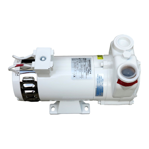
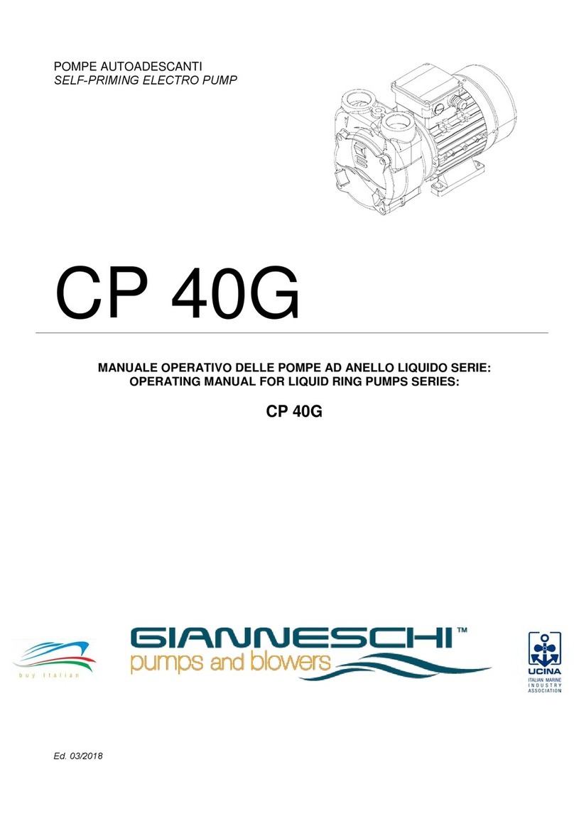
Gianneschi ACB 531 Series User manual

POMPE AUTOADESCANTI
SELF-PRIMING ELECTRO PUMP
ACB 531
MANUALE OPERATIVO DELLE POMPE CENTRIFUGHE AUTOADESCANTI:
OPERATING MANUAL FOR CENTRIFUGAL SELF-PRIMING PUMPS:
ACB 531/A
ACB 531/B
ACB 531/C
Ed. 04/2011

Gianneschi Pumps and Blowers s.r.l. - Via G. Pastore, n°19/21 –55040 Capezzano Pianore (LU) - ITALIA
Tel: +39 0584 969391 Fax: +39 0584 969411
Cod. Fisc. e P.Iva IT: 01619620469 –(REA 154940 Lucca) –Cap. Soc. 54.000 €
2
INDEX
1.0 .................................................................................................................................. INTRODUCTION 3
1.1 ............................................................................................................................ CONDITION OF USE 3
1.2 ..................................................................................................................PRELIMINARY INSPECTION 3
1.3 ......................................................................................................................STORAGE INSTRUCTION 3
1.4 ...............................................................................................................................................SAFETY 5
1.5 ....................................................................................................................................INSTALLATION 5
1.6 ................................................................................................................... ELECTRICAL CONNECTION 7
1.7 ...........................................................................................................................................STARTING 7
1.8 ...................................................................................................................................MAINTENANCE 8
1.8.1 .......................................................................................................................... MECHANICAL SEAL 8
1.9 ......................................................................................................................................SPARE PARTS 9
1.9.1 .............................................. SOBSTITUTION OF THE IMPELLER, MECHANICAL SEAL AND BEARINGS 11
INDICE
2.0 .................................................................................................................................. INTRODUZIONE 15
2.1 .....................................................................................................................CONDIZIONI DI IMPIEGO 15
2.2 ....................................................................................................................CONTROLLI PRELIMINARI 15
2.3 ......................................................................................................................................STOCCAGGIO 15
2.4 ......................................................................................................................................... SICUREZZA 17
2.5 .................................................................................................................. COLLEGAMENTI ELETTRICI 17
2.6 ......................................................................................................... INSTALLAZIONE E AVVIAMENTO 18
2.7 ................................................................................................................................ MANUTENZIONE 20
2.7.1 ....................................................................................................................... TENUTA MECCANICA 20
2.8 ............................................................................................................................ PARTI DI RICAMBIO 21
2.8.1 ........................................................................................................................... DISEGNO ESPLOSO 22
2.8.2 .................................................... SOSTITUZIONE DELLA GIRANTE, DELLA TENUTA E DEI CUSCINETTI 23

Gianneschi Pumps and Blowers s.r.l. - Via G. Pastore, n°19/21 –55040 Capezzano Pianore (LU) - ITALIA
Tel: +39 0584 969391 Fax: +39 0584 969411
Cod. Fisc. e P.Iva IT: 01619620469 –(REA 154940 Lucca) –Cap. Soc. 54.000 €
3
1.0 INTRODUCTION
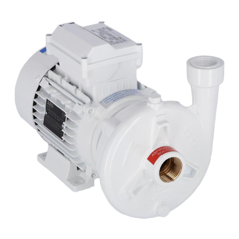
This booklet describes the operating procedures for ACB 531 series el/pump.
These pumps are usually used for marine application, to pump sea and fresh water, diesel oil, not
inflammables liquids and liquids without suspended parts.
Most common uses are: Bilge, Diesel and Oil Transfer, Fire-Fighting, plant supply or where
required a pump with a good flow rate.
Standard construction is with bronze body pump and impeller.
The use of these machines must be made by qualified and experienced personnel, in full
compliance with local legislation.
These instructions should be carefully read before installation of any ACB 531 series pump.
The manufacturer declines all responsibility in case of accident or damage due to
negligence or lack of observance of instructions given in this booklet, or application in
conditions not conforming to detail on the motor plate. All responsibility is also declined for
damage caused by improper use of the pump
1.1 CONDITION OF USE
These el/pumps must be used with clean liquids in this conditions:
- Max pressure admitted in the pump casing 8 Bar
- Max suction depth 8m
- Temperature of the liquid from -5°C to +60°C
- Acustic level <85 dB
- Pump abrasive liquids Not admitted
1.2 PRELIMINARY INSPECTION
Unpack the pump and check its integrity. Furthermore check that the data on the plate corresponds
to the data required and that the shaft turns freely. If there is any irregularity, contact the
GIANNESCHI Pumps and Blowers immediately, signalling the nature of the discrepancy.
CAUTION: If there is any doubt about safety of the pump, do not use it.
1.3 STORAGE INSTRUCTION
After receipt and inspection the unit, if not immediately installed, the unit must be repackaged and
stored in the best way.
For a proper storage proceed as follows:
- Store the pump in a location witch is closed, clean, dry and free of vibrations.
- Do not store in areas with less than 5°C temperature (for lower temperature it’s
necessary to completely the drain the pump of any liquids which are subject to
freezing)
- Fill the pump with a rust-preventative liquid that is compatible with the pump gaskets
and elastomers. Rotate the shaft by hand to impregnate all internal surface. Drain
the excessive liquid from the pump and months.
- Cover the pump with plastic sheet or similar protective material.
-

Gianneschi Pumps and Blowers s.r.l. - Via G. Pastore, n°19/21 –55040 Capezzano Pianore (LU) - ITALIA
Tel: +39 0584 969391 Fax: +39 0584 969411
Cod. Fisc. e P.Iva IT: 01619620469 –(REA 154940 Lucca) –Cap. Soc. 54.000 €
4
Fig. 1 Example of Lifting

Gianneschi Pumps and Blowers s.r.l. - Via G. Pastore, n°19/21 –55040 Capezzano Pianore (LU) - ITALIA
Tel: +39 0584 969391 Fax: +39 0584 969411
Cod. Fisc. e P.Iva IT: 01619620469 –(REA 154940 Lucca) –Cap. Soc. 54.000 €
5
1.4 SAFETY
- Before installation, ensure that mains supply is grounded in accordance with local
legislation and corresponds to motor plate detail
- Before carrying out any maintenance, ensure safety by switching off main voltage and
removing pump plug from socket.
- The machines are electrically supplied: avoid contact between the liquid pumped and
electrical part of the machine.
- The motor may become hot when running keep attention.
- The pump must only be repaired by competent or qualified personnel
Using manufacturer’s spares. If this procedure is not followed, GIANNESCHI Pumps and
Blowers decline any responsibility and warranty is invalid.
1.5 INSTALLATION
Correct installation can be complex and should nly be undertaken by qualified, experienced
personnel. CAUTION: During installation all regulation for safety and good practice must be
followed.
Install the pump in a dry and well ventilated location with room temperature not above +50°C: The
machine must be placed on a solid and clean surface in horizontal position, feet down. To reduce
vibration block the machine with the bolts to the surface and install some vibration dumpers.
Pipes: Install the pipes well anchored on their own supports near the inlet and outlet points of the
pump to avoid their transmitting any vibration. Ensure the pipes are fully sealed with jointing
compound to the pump ports. From internal diameter of pipes, which can never be less than the
diameter of the pump connections, depends the delivery of the pump. Pumps are supplied with
thread ports, so three pieces pipe union is recommended at suction and delivery ports. With rigid
pipe, a damper joint (flexible connection) should be installed close to the pump to reduce stress on
the pump head.
Check all pumps are clear and free of obstruction or retraction. Check that suction and delivery
pipes are correctly connected to pumps ports.
Suction Pipes:
For suction pipe length in excess of 10mt, or where there are many curves use pipe with bigger
diameter. Suction pipe must be completely air thigh with continuous upward slope to pump inlet, to
avoid air-lack.
A strainer should be fitted in the suction line to stop foreign substances from damaging the pump.
A vacuum gauge is recommended where pump performance needs to be closely monitored as well
a non-returned valve and sluice valve.
Delivery Pipe:
On delivery pipe, that should be air-tight , install a sluice valve and a manometer.

Gianneschi Pumps and Blowers s.r.l. - Via G. Pastore, n°19/21 –55040 Capezzano Pianore (LU) - ITALIA
Tel: +39 0584 969391 Fax: +39 0584 969411
Cod. Fisc. e P.Iva IT: 01619620469 –(REA 154940 Lucca) –Cap. Soc. 54.000 €
6

Gianneschi Pumps and Blowers s.r.l. - Via G. Pastore, n°19/21 –55040 Capezzano Pianore (LU) - ITALIA
Tel: +39 0584 969391 Fax: +39 0584 969411
Cod. Fisc. e P.Iva IT: 01619620469 –(REA 154940 Lucca) –Cap. Soc. 54.000 €
7
1.6 ELECTRICAL CONNECTIONS
Electrical connections must be made exclusively by qualified personnel in accordance
with the
instructions from the manufacturer of the motor or other electrical components and
must adhere to the local National Electrical Code.
It is recommended that electric motors and eventual connected accessories be protected against
overloading by means of circuit breakers and/or fuses.
Circuit breakers and fuses must be sized in accordance with the full load amperage appearing on
the motor nameplate.
It is advisable to have an electrical switch near the pump for emergency situations. Prior to
connecting the electrical wiring, turn the pump shaft by hand to make sure that it rotates freely.
Connect the electrical wiring in accordance with local electrical codes and be sure to ground the
motor.
Motor connection should be as indicated on the motor tag (frequency, voltage, poles and max
consumption) and as discussed in the motor instruction manual.
It is recommended that motors 7.5 kW be wired for Star-Delta start-up, to avoid electrical overloads
to the motor and mechanical overloads to the pump.
Be sure to replace all safety guards before switching on the electrical power.
If possible check the direction of rotation before the motor is coupled to the pump but protect the
motor shaft to prevent any accidents. When this is not possible briefly jog the pump to check its
direction of rotation (see arrow on pump for correct rotation). If the direction must be changed two
of the three electrical wire leads must be alternated with each other (at the terminal box or at the
motor starter).
Please be aware that rotation in the wrong direction and/or pump running dry may cause severe
pump damage.
Electrical instrumentation such as solenoid valves, level switches, temperature switches, flow
switches, etc. which are supplied with the pump or systems must be connected and handled in
accordance with the instructions supplied by their respective manufacturers.
1.7 STARTING
Check the shaft turns freely (an hexagonal key or a screwdriver
should be into the slot of the shaft).
FILL THE BODY PUMP THROUGH THE DELIVERY
HOLE (Part N. 13) TO PRIME THE PUMP.
NEVER RUN PUMP DRY
This is an important operation that has to done at first
starting and each time the body pump is empty to avoid
damage.
Start the pump with the delivery sluice valve closed and that one
open in suction, then, open slowly the delivery sluice valve.
Check the rotation sense of the motor. Make sure that the motor
is working in its performance data field and that the current
absorbed recommended on the plate is not exceeded.

Gianneschi Pumps and Blowers s.r.l. - Via G. Pastore, n°19/21 –55040 Capezzano Pianore (LU) - ITALIA
Tel: +39 0584 969391 Fax: +39 0584 969411
Cod. Fisc. e P.Iva IT: 01619620469 –(REA 154940 Lucca) –Cap. Soc. 54.000 €
8
1.8 MAINTENANCE
Before doing anything, ensure the machine is disconnected from the power
source and that there is no possibility of accidental connection.
These machines usually do not need any maintenance so long the following precautions are taken.
- If there is a risk of freezing, it’s necessary to empty the pump casing then fill the pump up
before it gets Woking again.
- Make sure the pump never works dry.
- If the pump does not work for a long time it is better to empty the pump casing and clean it.
- If a filter and a foot valve are installed, check periodically their integrity and cleanness.
- The impeller never can’t blocked. If it happens, a descaling of the impeller and casing pump
must be done.
1.8.1 MECHANICAL SEAL
- Purpose of mechanical seals is to retain handled product inside the pump in the area where
the shaft exits the pump casing.
- To assure maximum reliability and safe operation Gianneschi Pumps and Blowers
evaluates seal choices at time of pump selection in connection with customer’s
requirements, application and liquid details.
- Mechanical seals do not require maintenance until losses of liquid are visible.
- Mechanical Seals should NEVER run dry.
- It’s recommended to check the wear on seal faces every 1000 working hours.

Gianneschi Pumps and Blowers s.r.l. - Via G. Pastore, n°19/21 –55040 Capezzano Pianore (LU) - ITALIA
Tel: +39 0584 969391 Fax: +39 0584 969411
Cod. Fisc. e P.Iva IT: 01619620469 –(REA 154940 Lucca) –Cap. Soc. 54.000 €
9
1.9 SPARE PARTS
1. Screw for cover fixing
2. Pump cover
3. Impeller
4. Screw for internal disk
5. O-Ring
6. Internal disk
7. Seeger
8. Spacer
9. Mechanical seal
10. Counter face
11. Body pump
12. Washer
13. Priming Cap
14. Oil Seal
15. Seeger
16. Front bearing
17. Adapter shaft key
18. Adapter shaft
19. Back bearing
20. Seeger
21. Connection flange
22. Flange/Pump fixing screw
23. Flange/Motor fixing screw
24. Motor key
25. Electric Motor
26. Counter flange bolt
27. Counter flange
28. Gasket
29. Nut

Gianneschi Pumps and Blowers s.r.l. - Via G. Pastore, n°19/21 –55040 Capezzano Pianore (LU) - ITALIA
Tel: +39 0584 969391 Fax: +39 0584 969411
Cod. Fisc. e P.Iva IT: 01619620469 –(REA 154940 Lucca) –Cap. Soc. 54.000 €
10
1.9.1 EXPLODED DRAWING

Gianneschi Pumps and Blowers s.r.l. - Via G. Pastore, n°19/21 –55040 Capezzano Pianore (LU) - ITALIA
Tel: +39 0584 969391 Fax: +39 0584 969411
Cod. Fisc. e P.Iva IT: 01619620469 –(REA 154940 Lucca) –Cap. Soc. 54.000 €
11
1.9.1 SOBSTITUTION OF THE IMPELLER, MECHANICAL SEAL AND
BEARINGS
1. Unscrew the 6 screw of the body
pump with the front cup.
2. Take the front cup (Part. 2)
3. Extract the Impeller (Part. 3) and the
Impeller Key (Part. 17)
4. Unscrew the 2 internal M6 screw
(Part. 4)
5. Tighten two M8 screw to allowed the
internal disk extraction
6. Extract the internal disk (Part. 6),
please attention to O-Ring (Part 5)

Gianneschi Pumps and Blowers s.r.l. - Via G. Pastore, n°19/21 –55040 Capezzano Pianore (LU) - ITALIA
Tel: +39 0584 969391 Fax: +39 0584 969411
Cod. Fisc. e P.Iva IT: 01619620469 –(REA 154940 Lucca) –Cap. Soc. 54.000 €
12
7. Remove the Seeger (Part. 7), the
spacer and the mechanical seal (Part.
9) with its graphite ring (Part.10)
8. Unscrew the 4 body pump screw
(Part. 23)
9. Remove the body pump (Part. 11) if it’s
necessary using the rubber hammer
10. Unscrew the 4 screw for fixing the
flange to the motor (Part. 22)
11. Extract the flange (Part. 21) with the
shaft (Part. 18) and the bearing (Part.
16 and 19), if it’s necessary using the
rubber hammer
12. Remove the Oil-Seal (Part. 14)

Gianneschi Pumps and Blowers s.r.l. - Via G. Pastore, n°19/21 –55040 Capezzano Pianore (LU) - ITALIA
Tel: +39 0584 969391 Fax: +39 0584 969411
Cod. Fisc. e P.Iva IT: 01619620469 –(REA 154940 Lucca) –Cap. Soc. 54.000 €
13
13. Remove the internal front (Part.
15)and back Seeger (Part. 20)
14. Extract the shaft (Part. 18) with the
bearings (Part. 16 and 19); if it’s
necessary using the rubber hammer
15. Remove the bearings (Part. 16 and
19)
To reassemble all the pumps, is better to work in the reverse system, changing the O-Ring
(Part. 5).
ATTENTION: The honed faces of the mechanical seal must be at contact
- Clean Accurately all seals of mechanical seal
- Lube with glycerine all packing
- Clean accurately with alcohol the faces of mechanical seal.

Gianneschi Pumps and Blowers s.r.l. - Via G. Pastore, n°19/21 –55040 Capezzano Pianore (LU) - ITALIA
Tel: +39 0584 969391 Fax: +39 0584 969411
Cod. Fisc. e P.Iva IT: 01619620469 –(REA 154940 Lucca) –Cap. Soc. 54.000 €
14
DEFECT AND RESOLUTION
DEFECT
CAUSE
SOLUTION
- The Motor does not
start
- No Voltage
- Check the value of the
line voltage
- Impeller Blocked
- Clean the impeller and
the pump casing
- Motor detective
- Consult a Gianneschi
Service or dealer
- The motor run but the
pump not work
- Valve and filter dirty
- Clean valve and filter
- Suction depth to height
- Install the pump neas
the water static level
- Air in suction
- Check the air-tightness
of the pipe
- The pump was not fill
up with water
- Fill up the pump
- Wrong direction of
rotation
- Invert two polarity
- The pump make noise
- Air in the pipes
- Put out the air
- Insufficient pressure
- The liquid has too
viscosity
- Check the viscosity if
the liquid
- Impeller and diffuser
damaged
- Replace the parts
- Pressure request by
the system other than
the possibility of the
pump
- Change the pump
model

Gianneschi Pumps and Blowers s.r.l. - Via G. Pastore, n°19/21 –55040 Capezzano Pianore (LU) - ITALIA
Tel: +39 0584 969391 Fax: +39 0584 969411
Cod. Fisc. e P.Iva IT: 01619620469 –(REA 154940 Lucca) –Cap. Soc. 54.000 €
15
2.0 INTRODUZIONE
Questo fascicolo descrive le istruzioni d’uso e manutenzione delle elettropompe serie ACB 531.
Tali elettropompe, per la loro estrema affidabilità, durata, semplicità d’uso, sono comunemente
utilizzate in campo nautico, in particolare per il pompaggio di acqua di mare, acqua dolce, gasolio,
acque grigie, liquidi non infiammabili e liquidi puliti senza parti in sospensione, per applicazioni di
esaurimento sentina, sentina principale, antincendio, travaso gasolio, alimentazione impianti e
dove si richiede un eccellente capacità di auto-innesco; tali pompe, grazie al loro particolare profilo
idraulico, possono raggiungere valori di portata superiori alle normali pompe a canale laterale.
L’esecuzione particolarmente compatta, è comunque dotata di giunto rigido con doppio cuscinetto
di supporto.
L’utilizzo di queste elettropompe deve essere eseguito da personale competente ed è subordinato
alle direttive delle legislazioni locali.
Prima di installare le elettropompe è indispensabile leggere attentamente questo opuscolo:
la Gianneschi Pumps and Blowers S.r.l. declina ogni responsabilità in caso di incidente
dovuto a negligenza o alla mancata osservanza delle istruzioni di seguito descritte; declina
altresì ogni responsabilità per danni causati da un uso improprio del prodotto.
2.1 CONDIZIONI DI IMPIEGO
Queste elettropompe devono essere utilizzate con liquidi puliti entro queste condizioni:
- Pressione statica massima ammessa nel corpo pompa 8 Bar
- Massima profondità di aspirazione 8 Mt.
- Temperatura del liquido da pompare da -5°C a +60°C
- Livello di rumorosità <85dB
- Pompaggio di liquidi abrasivi Non Ammesso
2.2 CONTROLLI PRELIMINARI
Estrarre l’elettropompa dall’ imballo e verificarne l’integrità: verificare inoltre che i dati di targa
corrispondano a quelli desiderati e che l’asse della pompa giri liberamente, in caso contrario
contattare immediatamente la Gianneschi Pumps and Blowers S.r.l.
ATTENZIONE: In caso di dubbi sulla sicurezza della macchina non utilizzarla.
2.3 STOCCAGGIO
Se dopo il ricevimento ed il controllo la pompa non sarà immediatamente installata sull'impianto
essa dovrà essere re imballata ed immagazzinata nel migliore dei modi.
Per lo stoccaggio e l’immagazzinamento della pompa è opportuno attenersi alle seguenti
indicazioni precauzionali:
- riporre la pompa in un luogo chiuso, pulito, asciutto, non esposto ai raggi solari e privo di
vibrazioni
- evitare che la temperatura scenda sotto i 5°C
- riempire la pompa con un liquido protettivo, compatibile con le guarnizioni e gli elastomeri
presenti nella pompa, e ruotarla a mano per impregnare tutte le superfici interne drenare in seguito
la pompa e tutte le tubazioni collegate.

Gianneschi Pumps and Blowers s.r.l. - Via G. Pastore, n°19/21 –55040 Capezzano Pianore (LU) - ITALIA
Tel: +39 0584 969391 Fax: +39 0584 969411
Cod. Fisc. e P.Iva IT: 01619620469 –(REA 154940 Lucca) –Cap. Soc. 54.000 €
16
un’ulteriore soluzione, specialmente per un immagazzinamento prolungato, è quella di riempire
totalmente la pompa con un liquido protettivo idoneo per tutti i componenti della pompa avendo
cura di evitare il formarsi di sacche d’aria.
- chiudere ogni foro ed apertura che comunica con l'interno della pompa
- proteggere tutte le parti esterne lavorate con prodotti antiruggine
- ricoprire la pompa con un telo di materiale impermeabile
- almeno ogni mese far ruotare per alcuni giri la parte rotante dell'albero della pompa per evitare
possibili incrostazioni e/o bloccaggi
- riservare lo stesso trattamento a tutti gli equipaggiamenti supplementari della pompa.
Fig. 1 Esempi di sollevamento

Gianneschi Pumps and Blowers s.r.l. - Via G. Pastore, n°19/21 –55040 Capezzano Pianore (LU) - ITALIA
Tel: +39 0584 969391 Fax: +39 0584 969411
Cod. Fisc. e P.Iva IT: 01619620469 –(REA 154940 Lucca) –Cap. Soc. 54.000 €
17
2.4 SICUREZZA
Le elettropompe serie ACB 531 sono conformi alla direttiva 2006/42/CE. Tali conformità decadono
qualora il prodotto non fosse installato su di un impianto o una macchina dichiarante conforme a
questa direttiva.
- Prima dell’ installazione assicurarsi che la rete di alimentazione sia conforme alle norme
vigenti, sia dotata di messa a terra e risponda ai dati di targa del motore.
- Prima di qualsiasi intervento di manutenzione assicurarsi che la pompa sia totalmente
scollegata dall’ impianto elettrico.
- Poiché l’elettropompa è alimentata elettricamente, evitare il contatto tra quest’ ultima ed il
liquido da pompare.
- Durante il funzionamento il motore elettrico può essere caldo; porre attenzione!
- L’elettropompa deve essere riparata esclusivamente da personale autorizzato e
qualificato, che deve utilizzare solo ed esclusivamente ricambi originali Gianneschi; qualora
questo non venisse rispettato, la Gianneschi Pumps and Blowers S.r.l. si esonera da ogni
responsabilità e la garanzia perde il suo valore.
2.5 COLLEGAMENTI ELETTRICI
I collegamenti elettrici devono essere esclusivamente effettuati da personale
specializzato che dovrà attenersi alle istruzioni del costruttore del motore e delle
apparecchiature elettriche ed alle normative nazionali previste.
ATTENERSI ALLE PRESCRIZIONI DI SICUREZZA.
TUTTI I LAVORI DEVONO ESSERE ESEGUITI IN ASSENZA DI TENSIONE
ELETTRICA.
E' raccomandabile che tutti i componenti elettrici (motore della pompa centrifuga ed eventuali
accessori collegati) siano protetti contro il sovraccarico con opportuni interruttori e/o fusibili.
L'intensità di corrente a pieno carico, stampata sulla targhetta del motore, deve essere usata per
selezionare l'adeguato grado di protezione.
E' consigliabile prevedere un pulsante di emergenza in posizione agevole nei pressi della pompa.
Prima di effettuare i collegamenti elettrici far girare la pompa ed il motore a mano per verificare se
ruotano liberamente.
Effettuare correttamente, secondo le norme vigenti, i collegamenti elettrici senza trascurare la
messa a terra del motore.
Collegare i morsetti rispettando i dati di targa del motore (frequenza, tensione, numero delle fasi e
consumo max.) leggendo attentamente le eventuali ulteriori istruzioni che accompagnano il motore
stesso.
Per motori con potenza 7,5 kW è raccomandato di predisporre l’avviamento con collegamento a
stella-triangolo al fine di evitare sovraccarichi elettrici al motore e meccanici alla pompa.
Ricordarsi di riposizionare tutte le protezioni esistenti prima di ridare tensione alla linea.
Se possibile, verificare il senso di rotazione del elettropompa prima dell’ avviamento,
proteggendone accuratamente l’albero al fine di evitare possibili incidenti, altrimenti far funzionare
il gruppo elettropompa per un tempo brevissimo dopo avere completato e verificato l’intera
installazione (la rotazione contraria e/o a
secco può causare danni molto seri): se dovesse ruotare in senso contrario (sulla pompa è
indicato con una freccia il senso corretto di rotazione) occorre scambiare tra loro 2 dei 3 cavi di
alimentazione del motore.
L’eventuale strumentazione elettrica (es.: elettrovalvole, livellostati, termostati, flussostati, ecc.)
fornita con la pompa dovrà essere collegata seguendo le istruzioni e le relative prescrizioni di
sicurezza che le accompagnano.

Gianneschi Pumps and Blowers s.r.l. - Via G. Pastore, n°19/21 –55040 Capezzano Pianore (LU) - ITALIA
Tel: +39 0584 969391 Fax: +39 0584 969411
Cod. Fisc. e P.Iva IT: 01619620469 –(REA 154940 Lucca) –Cap. Soc. 54.000 €
18
2.6 INSTALLAZIONE E AVVIAMENTO
Controllare che l’asse della pompa giri liberamente (questo è possibile inserendo l’apposita chiave
o cacciavite nella parte posteriore dell’ asse motore)
Installare la pompa in luogo asciutto e correttamente ventilato, con temperatura ambiente non
superiore ai +50°C.
Posizionare la elettropompa in posizione orizzontale, correttamente fissata al contro-basamento,
per ridurre le vibrazioni si consiglia di installare sempre degli antivibranti.
Montare le tubazioni di aspirazione e mandata in maniera corretta, verificando il corretto serraggio
dei bulloni di fissaggio; NON installare tubazioni di DN inferiore a quello nominale delle flange della
elettropompa, in caso di tubazioni di DN differente le prestazioni della pompa potrebbero variare a
seconda della tubazione installata.
Verificare che le tubazioni siano correttamente sigillate e che non vi siano perdite nell’ impianto;
NB, una perdita nella tubazione di aspirazione può far entrare aria all’ interno del corpo pompa e
comprometterne il corretto adescamento.
Se la tubazione di aspirazione supera i 10mt totali di lunghezza, si consiglia di installare una
tubazione di diametro maggiore.
Installare sulla tubazione di mandata valvole e manometri.
PRIMA DELL’ AVVIO RIEMPIRE IL CORPO POMPA MEDIANTE
GLI APPOSITI FORI REALIZZATI (Componente N. 13)
NON FAR GIRARE MAI LA POMPA A SECCO
Avviare la pompa con la saracinesca di mandata chiusa e quella di
aspirazione completamente aperta, aprire poi, lentamente, la
saracinesca di mandata. Controllare il verso di rotazione, che
l’elettropompa lavori entro il suo campo di prestazione e che non
venga superata la corrente assorbita indicata in targa.

Gianneschi Pumps and Blowers s.r.l. - Via G. Pastore, n°19/21 –55040 Capezzano Pianore (LU) - ITALIA
Tel: +39 0584 969391 Fax: +39 0584 969411
Cod. Fisc. e P.Iva IT: 01619620469 –(REA 154940 Lucca) –Cap. Soc. 54.000 €
19

Gianneschi Pumps and Blowers s.r.l. - Via G. Pastore, n°19/21 –55040 Capezzano Pianore (LU) - ITALIA
Tel: +39 0584 969391 Fax: +39 0584 969411
Cod. Fisc. e P.Iva IT: 01619620469 –(REA 154940 Lucca) –Cap. Soc. 54.000 €
20
2.7 MANUTENZIONE
Prima di ogni intervento assicurarsi che la tensione sia staccata e che non ci
siano possibilità di connessioni accidentali.
Le elettropompe, generalmente, non necessitano di manutenzione ordinaria, purché
siano presi alcuni accorgimenti che ne prolungano l’esercizio.
- Dove esiste il pericolo di gelate, è necessario svuotare il corpo pompa dal liquido
e quindi riempirlo nuovamente prima di rimettere la pompa in funzione
oNON FAR GIRARE LA POMPA A SECCO
- Se la pompa deve rimanere per un lungo periodo inattiva, è auspicabile lo svuotamento del
corpo pompa e la pulizia della stessa.
- Dove sia installata una valvola di fondo ed il filtro in aspirazione controllare periodicamente
l’efficienza e la pulizia.
- Verificare se la girante non sia mai bloccata, questo comporterebbe gravi danni al motore
elettrico, se ciò avvenisse, provvedere alla disincrostazione della girante e del corpo
pompa.
2.7.1 TENUTA MECCANICA
Scopo delle Tenute Meccaniche è contenere il liquido pompato all’interno della pompa nell’area di
passaggio dell’albero.
Le tenute meccaniche possono essere di diversi tipi di materiali, esecuzioni ed installazioni.
La corretta scelta è stata valutata in fase di progettazione dalla GIANNESCHI PUMPS a seguito
delle indicazioni fornite dal cliente in funzione del liquido e delle condizioni d’esercizio tale da
garantire la massima affidabilità e sicurezza durante il funzionamento.
Le elettropompe serie ACB montano tenute meccaniche del tipo singolo auto flussata (API Plan
01, 02 o 11) non è necessario predisporre alcun sistema di flussaggio e/o pressurizzazione in
quanto la costruzione della pompa ne permette la corretta lubrificazione e mantenimento delle
pressioni ideali.
Le tenute meccaniche solitamente non richiedono di manutenzione finché non si vedono perdite di
liquido (per la loro sostituzione vedere le istruzioni di smontaggio e montaggio).
Le tenute non devono MAI funzionare a secco!
Si consiglia comunque di verificare lo stato di usura delle facce ogni circa 1000 ore di
funzionamento in normale utilizzo.
Table of contents
Languages:
Other Gianneschi Water Pump manuals

Gianneschi
Gianneschi ECOINOX C.E. Operating instructions

Gianneschi
Gianneschi BMA-M Series User manual

Gianneschi
Gianneschi CP Series User manual

Gianneschi
Gianneschi CB Series User manual

Gianneschi
Gianneschi CP 40G Series User manual

Gianneschi
Gianneschi ACB 60 User manual

Gianneschi
Gianneschi EXCELSIOR User manual

Gianneschi
Gianneschi MVG User manual