Double Horse 9116 User manual

Double Horse 9116
Technical Manual
Compiled from contributions by owners of the DH9116 RC
helicopter and members of RC Groups Discussion Forums via the
“Double horse 9116 Heli” Thread at
http://www.rcgroups.com/forums/showthread.php?t=1540154

DH9116 Transmitter - Signal Code Bind
To re-establish the signal link between the helicopter and the transmitter by gaining access to the transmitters
automatic signal code synchronization mode (transmitter bind).
Make sure you plug in the battery to the helicopter first, but leave the switch off, make sure you keep the heli
within very easy reach. Also, make sure the throttle stick trim is set all the way down.
Hold the transmitter in your left hand, and hold down the throttle stick in the throttle off position, as far down
as it can go with your thumb (without straining or breaking the stick).
With your other hand, switch on the transmitter, and then within the first 5 seconds, while the transmitter is
still flashing and beeping, quickly switch on the helicopter.
A red LED inside the canopy will also flash quickly.
After 15 seconds, the red LED on the transmitter will stop flashing and it will stop beeping. Check to see if the
red LED inside the helicopter's canopy has also stopped flashing and is now "solid" or not blinking, if so, the
helicopter is now bound to the transmitter and you should hear both servos 'flutter" as they settle into the
transmitters pre-set servo settings.
To double check to see if the helicopter is properly bound to the transmitter, hold the heli in the palm of your
hand at arm’s length, and give the throttle stick a quick burst or throttle up, but still low enough so it doesn't
shoot up out of your hands and hit the ceiling. If the helicopter spins up, all is good. If not, you'll have to go
through the whole procedure again.

DH9116 Transmitter - Original Factory Program Menu Settings.
Terms used within the transmitter and this blog.
TX = Transmitter
ELEV = Elevator (cyclic movement forward or backward)
AILE = Aileron (cyclic movement side to side, slide left & right)
RUDD = Rudder (to increase or decrease tail rotor thrust, spin the tail left or right)
THRO = Throttle (increase or decrease motor rpm, to raise or lower the helicopter in altitude)
D/R = Dual Rate (increase or decrease servo maximum throw)
EPA = End Point Adjustment (increase or decrease to match the servo arm movements with transmitter control
stick travel)
Note: All stick trims are to be centered, throttle stick is at its lowest position; rocker switch is in the 'quick"
position.
Switch the TX on; the battery voltage indicator shows full and the actual voltage value flashes and fluctuates;
the red LED flashes and the buzzer beeps 14 times quickly, then changes to a higher pitch single beep, then
falls silent; the red LED also stops flashing (this is the end of the transmitter bind or helicopter to transmitter
signal synchronization mode).
Long press of the MENU button; after 1 second the backlight glows;
MODE Flashes; 2 is visible (to change modes, press up or down, press menu to save and exit)
Press of the MENU button and ELEV SUB F flashes - 000 ("F" suddenly appears next to the RUDD TRI)
press of the SEL button, AILE SUB L flashes - 000
press of the SEL button, THRO SUB F flashes - 000
press of the SEL button, RUDD SUB L flashes – 000
press of the SEL button, back to ELEV SUB F flashes – 000
press of the MENU button, ELEV D/R - 100%
press of the SEL button, AILE D/R flashes - 100%
press of the SEL button, RUDD D/R flashes - 100%
press of the SEL button, back to ELEV D/R flashes - 100%
press of the MENU button, ELEV REV flashes – REV
press of the SEL button, AILE REV flashes - REV
press of the SEL button, THRO REV flashes - NOA
press of the SEL button, RUDD REV flashes – REV
press of the SEL button, back to ELEV REV flashes – REV
press of the MENU button, ELEV EPA flashes - 100% (RUDD TRI changes to F)
To change the F to B, move the elevator stick forward or backward to change.
press of the SEL button, AILE EPA - 100% (RUDD TRI changes to R)
To change R to L, move the aileron stick side to side.
press of the SEL button, RUDD EPA - 100% (RUDD still at R)
To change the R to L, move the rudder stick side to side.
press of the SEL button, back to ELEV EPA flashes - 100% (RUDD TRI changes back to F)
press of the MENU button, THRO TRI 0 - 000%
press of the SEL button, THRO TRI 1 - 025%
press of the SEL button, THRO TRI 2 - 050%
press of the SEL button, THRO TRI 3 - 075%
press of the SEL button, THRO TRI 4 - 100%
press of the SEL button, back to THRO TRI 0 - 000%
press of the MENU button, back to mode - 2
END OF MENU

DH9116 Swashplate to Servo Arm Adjustable Linkage - Original
Factory Lengths
Factory lengths for both servo linkages. To increase in length, turn clockwise (left). To decrease in length, turn
anti or counter-clockwise (right).
The longest linkage with the outside (O.D) points of a digital vernier caliper should be 36mm (exactly
36.61mm), and with the inside (I.D) points of a digital vernier caliper the total overall length is 42mm (exactly
41.59mm)
The shortest linkage with the outside (O.D) points of a digital vernier caliper should be 26mm (exactly
26.32mm), and with the inside (I.D) points of a digital vernier caliper the total overall length is 32mm (exactly
31.21mm).
These lengths are base line measurements only. With these lengths, the helicopter should hover or take off
with a drift backwards and to the slightly to the right.
Proceed to the next section, to mechanically fine adjust the servo arm linkages to get a perfect hands-free
hover.

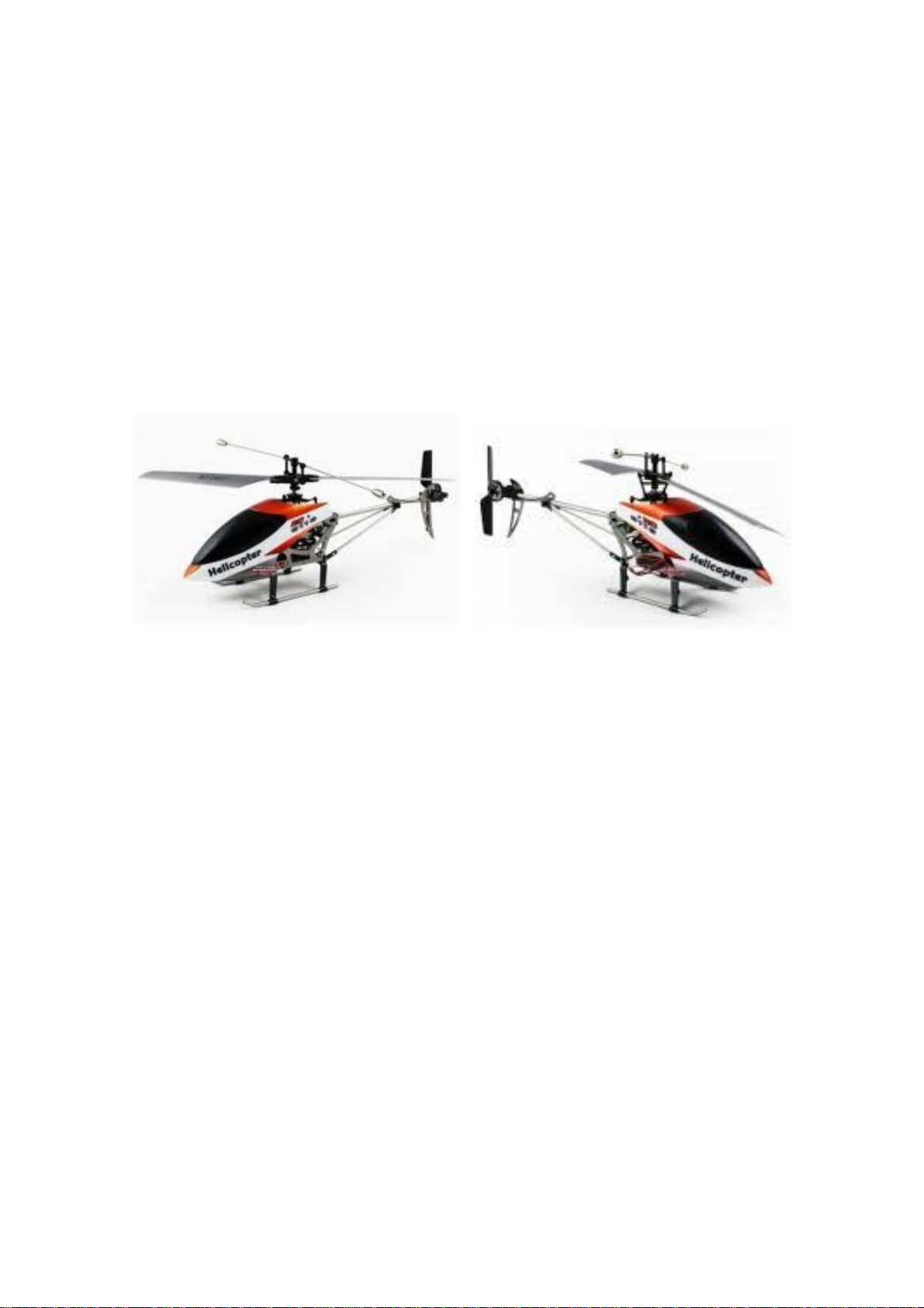
DH9116 Initial Basic Swashplate Leveling Procedure & Mechanical
Trimming / Adjustment of the Servo Arms & Linkages
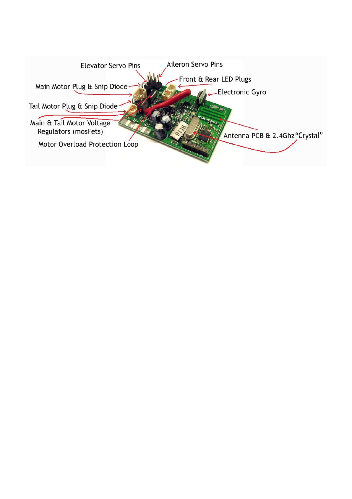
Remove the canopy and find the plugs to the tail motor and main motor on the pcb and pull them out (making
note of where they go), therefore disconnecting both the motors from the helicopter's battery power source.
Connect the battery to the helicopter, turn on your transmitter and switch on / power up the helicopter and
allow the helicopter to bind or sync with the transmitter, the servo's should flutter when it is bound. Centre all
the trims on the sticks on the TX and center all the sticks.
Place the helicopter on a level surface and in a position, so you can see it comfortably, you are going to be
doing this for 20 minutes or so. Make sure all the blades are in their shortest throw positions and the balance
bar is level (a small line level fixed to the balance bar is perfect for achieving this). Look at the swashplate and
ascertain if the top plate of the swash is at right angles or perpendicular to the main shaft. I find putting a long
thin knitting needle or a bamboo "satay" skewer stick on the top plate exaggerates the angle and makes it
more obvious. I have also found if you draw a thick horizontal and vertical line in the shape of a cross ("+") on
an "A4" sheet of paper, then temporarily position it on a wall (making sure it is perfectly horizontally and
vertically level before you fix it) directly behind the helicopter it can be used as reference marks for maintaining
the alignment of the main shaft and the swashplate leveling "stick". Adjust both servo arm linkages until the
swashplate is level along the length of the helicopter, re-attach the linkages to the swashplate, and re-connect
the tail and main motors and re-attach the canopy (re-attaching the canopy is important, because the weight of
the canopy will affect the balance of the helicopter and if it isn't on, hovering without it will give a false drift
backward).
Test fly / hover the helicopter. This must be done on a perfectly calm day or indoors well away from walls, etc.,
like a large shed or gym. Any slight breezes will influence or over-exaggerate any fine mechanical adjustments
you make, and you will be "chasing your own tail" trying to get it perfect.
Adjusting the position of the Servo arms.
Make sure first that you have fully re-charged the battery, then place the heli on a flat, level surface, like a
table or workbench top, and connect the battery and turn on the heli and the tx, allow then to bind and set the
throttle to zero, make sure all the stick trims on the tx are centred. This is to allow the servo's to stay at their
midpoint settings, because if the heli was switched off, you can move the servo and arms and knock them out
of central alignment. Unscrew the centre screw from the central pivot point on the servo arm and remove it,
pull the servo arm straight off (it might need prying or wriggling off), then re-align the inside grooves of the
servo arm with the corresponding grooves on the servo axle, so the arm is now horizontally level with the table
top (if you can't get it spot on, don't worry, it just needs to be as close as possible to 90°) and re-attach the
screw. Repeat the same procedure to the opposite side servo arm.
Servo Arm to Swashplate Link Adjustments.
To adjust the servo arm links to obtain a near perfect hands free hover, start with the swashplate levelling
procedure and re-set the servo arm links back to the factory lengths (but if you haven't adjusted them
previously, skip that bit, as they should be set to those lengths already). That is your starting point. At this
setting, the heli should take off with a bias to the rear and to the right. Once you get the heli airborne, attempt
to get it into a nose in hover, as close as to you as you can, so you can see the servo links rise and fall above
the top edge of the canopy, as you try to get the heli to hover stably with the sticks. If the heli wants to shoot
off to the left or right, as you are moving the sticks to counter it's movements, take note of which way the
servo link is going, if it goes down, that link needs to be shortened (screw in a clockwise direction) if it rises, it
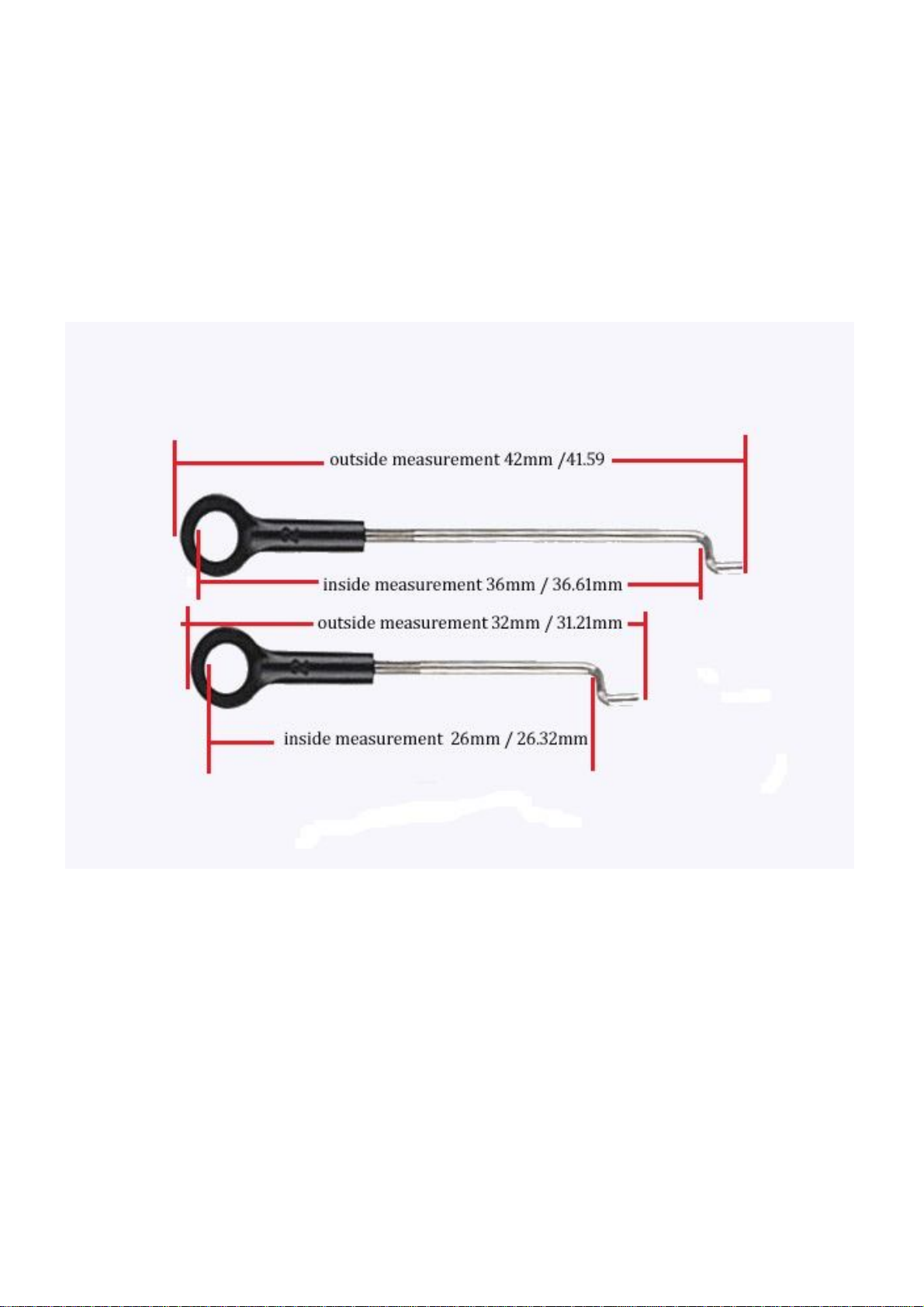
needs to be lengthened (screw out in a counter-clockwise direction). Bring the heli down and pop off that link
from the swashplate ball, by placing your fingernail behind the "ring" of the servo link and giving it a good
"flick". Screw in or out the servo link as required, in one full or one half turn increments, then press fit it back
on and go through the test hover procedure again. Only work on one direction at a time. Obviously, if the heli
wants to scoot off in a diagonal direction, you need to adjust both servo arm links, but only adjust one link at a
time, so to bring it back to a straight line drift (so it only wants to drift forwards or backwards, for instance).
For sliding/banking left or right ,you adjust the aileron servo (right hand side, looking from the tail). For
backward/forward drift, you adjust both servo links in equal amounts, but only after you've eliminated any side
to side drifting first.
A trimming in flight must be done on a 0 wind free day or a large indoor venue and it should take at least 1
fully charged battery, maybe 2 (so it should take about 30 - 45 minutes to do, maybe less, if you've got your
head around what you need to do first), to get it hovering close to perfect, because taking off and hovering
constantly requires optimum battery capacity. Ideally, the heli should take off near vertically and it should self-
level into a stable hover about 1.5 metres (head height) from the ground. So punch the throttle to get it
airbourne as quickly as possible, then get it into a hover. If the heli starts to loose altitude, even with a full
throttle stick, bring it down and re-charge it as soon as possible after you've let the battery cool down for 5 -
10 mins.

At this stage, we want to focus on the forward / backward drift, so focus on getting that as close to perfect as
possible, DO NOT WORRY ABOUT ANY SIDE DRIFT. You should have an ever so slight forward bias as it
takes off, not unlike a forward drift. If not, adjust both linkages one half turn at a time until you do (test fly /
hover after each adjustment). If you find after each successive adjustment, there is in a middle point between
forward and backwards and you just can't get it right, adjust it for a slight forward bias and then use the trims
on the sticks to get it hovering perfectly and balanced against forward / backward drift.
When you have it trimmed to compensate for forward and backward drift, make a note of any side drift and
what direction you move the aileron stick to correct that drift while it is hovering. If it is drifting to the left, the
right (aileron) servo arm linkage is too high, if it is drifting to the right, the right (aileron) servo arm linkage is
too low. There may be only one full or half turns to the link to bring it back, if the drift is severe, maybe it
needs more turns, adjust the link one half turn at a time and test hover after each adjustment until the drift
eliminated, if you find you can't get it perfect, fine tune it again with the tx stick trims, as required.
DH9116 Transmitter – Physically change from Mode 1 to Mode 2
In light of recent events (28th, June 2012) this change is now in two parts. The first part is the physical change,
the second, requires some minor soldering skills.
To physically change the TX sticks movements from Mode 1 to Mode 2, if you feel confident of having a go will
will take about 1/2 an hour or 45 minutes work and will only require a medium "jewellers" or "hobby" type,
phillips head (+) screwdriver, a soldering iron, some fine 0.7mm 60/40 resin cored solder and some “solder
braid” or wick. Unfortunately, you'll have to crack open the back of the TX. Before you physically change over
the sticks functions, make sure you have changed the mode in the program menu settings prior to starting.
Part One;
Remove all of your batteries and remove the 6 screws in the back of the main body and two smaller screws in
the handle with the medium Phillips head jeweller’s screwdriver. Gently open the back of the TX and slip out the
antenna pole from the back of the body, leaving it to remain on the front of the body. If you feel inclined slip
out the red and black wired battery power plug from the mainboard. Next, look inside the back of the TX and
you'll see the back of the sticks, move the stick you want to make into the throttle up and down (as you'd use it
as a throttle) and you'll see a small coiled spring stretch and retract, that's the spring you want to remove, it is
usually held in place by a small notched arm in the mechanism that works that side of the stick and a similar
device on the stick housing itself. Remove the top ring shaped part of the spring only from the side plate of the
housing at this stage (you'll work out how, it's pretty self-evident). Remove both screws on the top of the side
plate and gently insert a medium jewellers screwdriver or similar between the inside of the side plate itself and
the finely notched radius arm, and gently pry it up and away from the notched radius arm. When you've got it
out, you can slip free the bottom ring shaped part of the spring from the stick, if it hasn't fallen away already.
Put the spring and the side plate to one side for the time being. Do the same procedure to the stick you which
to make the throttle and reverse the procedure to install in their now new positions. Remove the screw from
metal lever type spring that is rubbing along the top of the opposite stick's finely notched radius arm and it's
adjacent screw from the side plate of the stick you want to make the throttle, turn it 180 degrees and slip the
side plate into the recesses where you took the other one from, and push it home, in the process making sure
the stick axle is also within the hole in the side plate (wriggle to stick to re-centre the axle into the hole if
needed), replace the top screw and position the angled part of the spring lever along the notched radius arm
and screw it in checking the tension of the spring lever to make sure it feels ok to you. It should be free, but
with a slight "notchy" feel and some minor resistance.
Part Two;
If you look at the electrical pots for the elevator / aileron stick and the throttle / rudder stick, you will notice all
but one is blue; the mode 1 throttle pot is however coloured green. You will need to physically swap the green
pot with the corresponding blue pot, which will require you to unsolder all the wires from the small pcb from
both pots, and physically swap the two pots over, then re-solder the wires back onto the small pcb on top of
the pots. The throttle stick pcb wire soldering sequence is; Top = Black, Middle = Green, Bottom = Red. The
elevator stick pcb wire soldering sequence is; Top = Black, Middle = White, Bottom = Red. Make sure there are
no “bridged” joins, and check the solders for continuity after.
Re-connect the battery power plug, if you removed it when you first opened the back of the TX. Re-install the
screws and batteries and turn the unit on. Double check that everything works within acceptable parameters,
but taking into account the new adjustments to the sticks and make sure the stick movements correspond to
the actions displayed on the LCD screen for Mode 2. If you find the new stick positions don’t correspond, switch
the Tx on and off a few times and it should change over automatically. I have physically converted one of my
TX’s from Mode 1 to Mode 2, to make sure the instructions I gave were as precise and detailed as possible.

DH9116 Servo Move Modification
To fix the servo arm link touching the canopy, when the servo is at full throw forward, and also, in my opinion,
to fix the excessive outward flexing of the servo arm.
The servo is usually removed by unplugging it from the pcb, then unscrewing the two retaining screws, and
simply pulling it out, but for this mod, I needed to move the servo inside between the two metal side plates by
5mm, so the servo screw tabs would have to be on the inside, not the outside. So I removed the servo
completely from the frame, then super-glued two small nuts to the inside of the tabs. I then removed enough
screws from one side of the side plate, and the main shaft and anti-rotation bar / top main shaft mounting
block, to allow me to slip the servo into position between the two sides of the frame. After a quick alignment to
estimate how much the servo needed to be moved, I found the width of a small section of cable/zip tie was just
wide enough to slip in between the body of the servo and the side plate, and also between the servo body and
the screws. This gave me the desired adjustment I needed to keep the servo aligned and in position. I then
positioned and fixed down the servo to the other servo by the use of some 2mm thick double sided foam tape,
for extra support and to help any additional flexing or stress on the servo mounting screw tabs.
Then I replaced all the parts and screws and checked the alignment of the servo arm and linkage with the ball
on the swashplate.

The image below left is of the servo at rest before the mod, then compare this image to the next image (below
right) of the servo at rest after the mod.
Once I checked everything was ok, I then switched the TX and the helicopter on and checked to see if the servo
arm no longer outwardly flexed and the linkage "dog leg" end was well clear of the canopy.
The below left image is as it was before, with the servo arm at full throw forward, right image is after the mod.
Table of contents
Other Double Horse Toy manuals
Popular Toy manuals by other brands

Lionel
Lionel 352 Icing Station owner's manual

Mattel
Mattel Hot Wheels Trick Tracks Ultimate Stunt World instructions

Eduard
Eduard Gloster Javelin FAW.9/9R air brakes quick start guide

Marvel
Marvel IRON MAN IRON THRUSTER quick start guide

marklin
marklin 37052 instruction manual

Smoby
Smoby 220314 quick start guide