Dover Triton 96 Series User manual

96XX
GROUNDING STRAP
FIELD INSTALLATION GUIDE
VERSION 2.0
TDN 07007-00002 05/01
COPYRIGHT NOTICE
Copyright © 2001 Triton Systems , Inc. All rights reserved. No part of this publication may
be reproduced, transmitted, transcribed, stored in a retrieval system, or translated into any
human or computer language, in any form, by any means whatsoever, without the express
written permission of Triton Systems, Inc.
CORPORATE HEADQUARTERS: RMA (RETURN MATERIAL AUTHORIZATION)
RETURN ADDRESS:
522 E. Railroad Street 21405 B Street
Long Beach, MS 39560 Long Beach, MS 39560
PHONE: (228) 868-1317
FAX: (228) 868-0437

TRITON SYSTEMS, INC.
96XX CASH DISPENSER
GROUNDING STRAP FIELD INSTALLATION GUIDE
2
FOLLOW THESE STEPS TO INSTALL THE 96XX
CASH DISPENSER GROUNDING STRAP:
1. Unlock and open the Cash Dispenser Control
Panel. Turn off the AC power to the terminal by
pushing the AC power switch (on the right side
of the Card Cage chassis) to the OFF (0) posi-
tion.
2. Connectthefirst ring terminal totheCardCage
chassis, as shown in Figure 2. You can identify
the first ring terminal by its location at the end of
a 17-inch long segment of the grounding strap.
3. Route the grounding strap to the speaker and
connectthesecond ring terminal tothespeaker
mounting screw, as shown in Figure 3.
DEILPPUSSTRAP SLOOTDEDNEMMOCER
1 03100-02190NP,partSdnuorGXX69 1 muideM,revirDwercSspillihP
1ytefasDSErof6egaPees(partStsirWDSE )secruostnempiuqednanoitamrofni
TO PROTECT THE EQUIPMENT FROM POTENTIALLY DAMAGING ELECTROSTATIC DIS-
CHARGE (ESD) EVENTS, WEAR A GROUNDED ESD WRIST STRAP DURING THE INSTALLA-
TION PROCEDURE! SEE PAGE 4 FOR INFORMATION ON ESD SAFETY AND SOURCES OF
ESD SAFETY EQUIPMENT.
Refer to Figure 1, Grounding Strap Routing Diagram. You will route the Grounding Strap between
six points, securing it at each point using one of the attached Ring Terminals. Each Ring Terminal will
fit under the existing screw/washer at each point. Remove the screw/washer, place the designated
Ring Terminal into position over the screw-hole, replace the screw/washer and tighten down.
NOITACOL NOITACOL
1
EGACDRAC
4
REDAERDRAC
2
REKAEPS
5
YLBMESSAYALPSID TEKCARBGNITNUOM
3
DRAOB)DEPS(DAPYEK
6
YLBMESSARETNIRP TEKCARBGNITNUOM
Figure 1. Grounding Strap Routing Diagram.
1
5
6
4
2
3
Figure 2. Connect Grounding Strap to
Card Cage chassis screw.

TRITON SYSTEMS, INC.
96XX CASH DISPENSER
GROUNDING STRAP FIELD INSTALLATION GUIDE
3
4. Connect the third ring terminal to the keypad
board mounting screw, as shown in Figure 4.
5. Connect the fourth ring terminal to the Card
Reader mounting screw. If the card reader has
an attached grounding wire, ensure the terminal
lug on this wire is secured to the same point as
the grounding strap ring terminal, as shown in
Figure 5.
6. Connect the fifth ring terminal to the Display
mounting screw, as shown in Figure 6.
7. Connect the sixth ring terminal to the Printer
Mounting Bracket, as shown in Figure 7.
8. Turn the AC power switch on the Card Cage to
the ON (I) position. Close and lock the Cash Dis-
penserControlPanel. The installation procedure
is complete.
Figure 3. Connect Grounding Strap to
Speaker mounting screw.
Figure 4. Connect Grounding Strap to
SPED board mounting screw.
Figure 5. Connect Grounding Strap to Card
Reader mounting screw and grounding
wire.
Card Reader grounding wire. Grounding Strap
Figure 6. Connect Grounding Strap to
Display mounting screw.
Figure 7. Connect Grounding Strap to
Printer Mounting Bracket screw.

TRITON SYSTEMS, INC.
96XX CASH DISPENSER
GROUNDING STRAP FIELD INSTALLATION GUIDE
4
ESD SAFETY
Electrostatic Discharge or "ESD" is a very common
electrical phenomenon. It is caused when a static
charge is suddenly released (discharged), causing
aflowof electric current and generating voltagesthat
can damage electronic components.
Static is produced by the contact and separation of
materials: shoes and floors, clothes and the human
body, parts being moved on or from surfaces. The
generated charge will reside on the body until it is
discharged. A common example occurs when you
walk across a carpeted floor and touch a doorknob.
Typically, you sense the discharge in the form of a
"zap,"abrief, possibly intense electrical jolt orshock.
Although such discharges need to be at least 3500
volts in order to be felt by the average individual,
voltagesoflessthan100voltscanpermanentlydam-
age or destroy electronic components.
ESDeventsdonotalwaysdestroyanelectroniccom-
ponent on the first occurrence. Sometimes, many
events are required, received over a period of time,
before the component finally fails.
Once the device fails completely, the failure is re-
ferred to as a catastrophic ESD failure. ESD dam-
age that is not catastrophic leaves the component
operable,but damaged, such that it can fail at a later
time, possibly under normal operation. In fact, most
ESD events are not catastrophic in nature, but cu-
mulative, and because of the microscopic nature of
ESD, when a catastrophic failure occurs you cannot
verify that ESD was the cause.
To reduce the possibility of ESD events when work-
ingonelectronic equipment, you should always wear
anESDwriststrapthat is plugged into a good ground
point.
A properly grounded wrist strap effectively prevents
anystatic charge from building up. Any static charge
that would tend to be created is instantly “drained”
by the wrist strap.
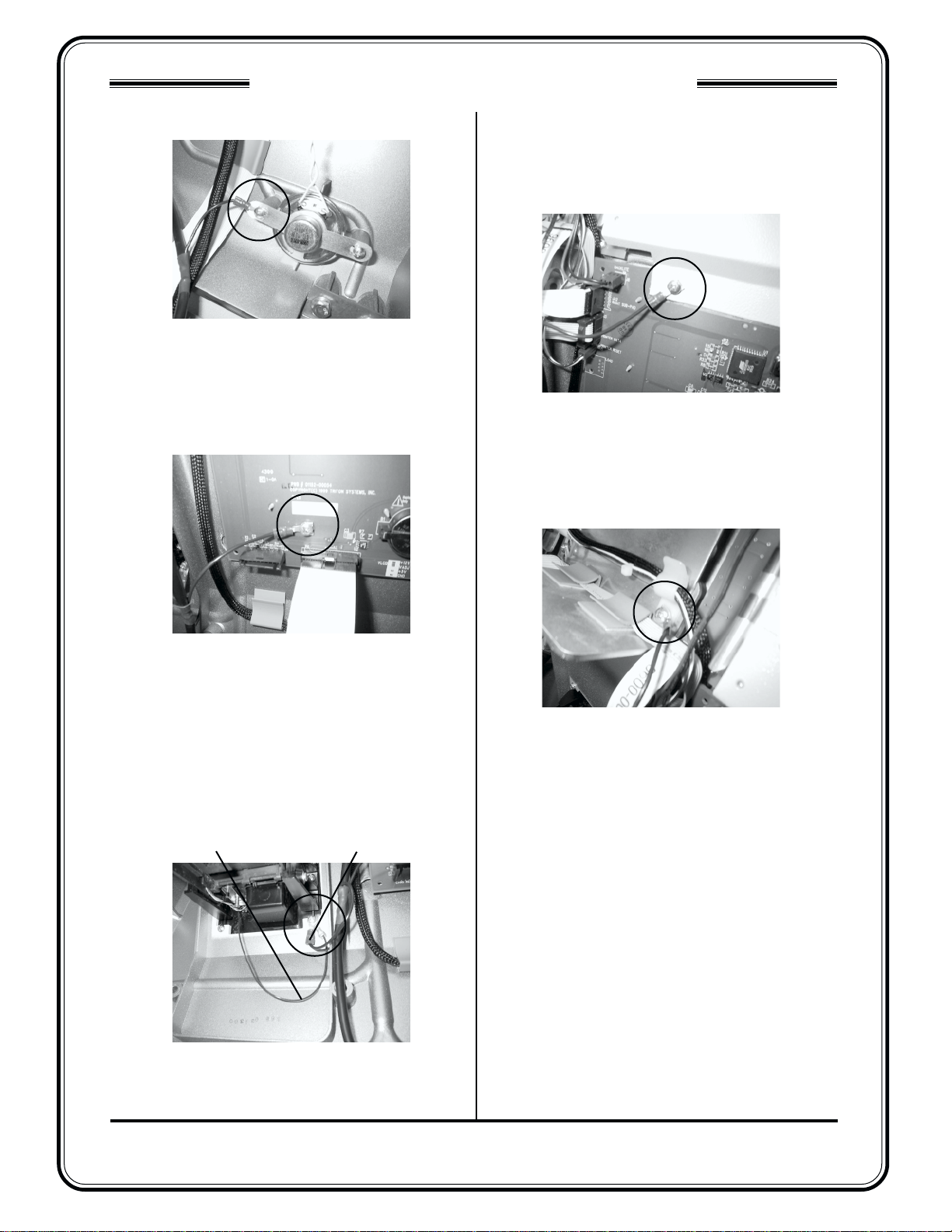
WRIST STRAP GROUND CONNECTION
Connect the wrist strap grounding cord to a
solidly grounded point! Once such point is the
pneumatic piston slide rail within the control panel
hood. Open the control panel hood to gain access to
the slide rail, as shown in Figure 8.
Youcanuseanalligatorclipadapter(provided in most
ESD safety kits) to connect the cord to the slide rail,
or to some other convenient grounding point.
The wrist strap grounding connection must be
maintainedat all times during thegrounding strap
installation procedure.
Figure 8. Grounding Point on Pneumatic
Piston Slide Rail.
Other manuals for Triton 96 Series
1
Other Dover Cash Register manuals