DPCAV PANDORA User manual

P
ANDORA
(
REV-C
), www.dpcav.com Page 1
©2007-2008 Jun-11-2008
Figure 2, Kit Contents
P
ANDORA
Pan & Tilt Kit (REV-C)
www.dpcav.com
The items shown in the photo below are provided in the kit. Be sure to check for missing parts
BEFORE your start assembly.
The following items are supplied by you:
1. Pan axis servo: Hyperion HP-DS12HCP or Hitec HS-81 R/C Servo. The HS-81MG (metal
gear) version is not recommended due to its limited travel range.
2. Tilt axis servo: Hitec HS-65HB R/C Servo. Alternate: generic 9-gram R/C servo, 20oz/in or
greater torque, max size 0.95"L x 0.45"W x 0.9"H.
3. Cased KX-131 (KT&C KPC-S226CB) or uncased Panasonic CX-161 CCD board camera.
4. 15 minute epoxy.
5. Loctite Threadlocker (Blue #242).
6. Manual or electric drill.
7. Screwdriver set.
8. Small file or sharp hobby knife.
9. Optional: 25W to 40W soldering iron and electrical solder.

P
ANDORA
(
REV-C
), www.dpcav.com Page 2
©2007-2008 Jun-11-2008
Figure 3, Main Chassis
Figure 4,
Solder Fillet
Assembly Tips:
1. You can build Pandora two ways: As a bottom (under carriage) mount or a top (cockpit view)
mount. The assembly steps for these two versions are nearly the same. Just follow the
instructions to build the version you need.
2. Pandora’s chassis construction uses simple tab and slot construction. Tabs are labeled with
single letters and the mating slots are labeled with a double letter. For example, Tab A goes to
Slot AA and Tab B goes to Slot BB. The identification text is printed on the chassis parts.
3. For the best fit, the Tab’s inside rounded corners should be filed or cut square. This will ensure
that the parts fit close together.
4. You may use fast curing Epoxy or a soldering iron to build your Pandora chassis. The
soldering method is best suited for experienced builders, but it will reduce the assembly time
considerably. That is because there is no waiting for the adhesive to dry.
5. Whenever you have any doubt on how something goes together, just review the various
photos. I suspect your questions will be resolved by reviewing the examples that are shown.
Chassis Assembly:
1. Using the details shown in Figures 1 and 2, gather
the left side panel (item 1), right side panel (item 2)
bottom chassis (item 3), front bulkhead (item 4)
and rear bulkhead (item 6). Dry fit the parts; trim
the inside corners of any tab that does not allow
proper seating in the mating slot.
Note: Be sure to install the panels so that their
circled ID numbers (
â
,
ã
,
ä
,
å
, and
ç
) are on the
inside of the chassis. Please review the photo for
the proper position of each panel.
2. Once everything fits properly, assemble them with
15-minute epoxy or use your soldering iron (your
choice).
Note: Soldering the chassis requires a fine fillet bead of solder
along the inside seams. Do not use too much solder! Your fillets
should look smooth and appear as shown in the figure on the left.

P
ANDORA
(
REV-C
), www.dpcav.com Page 3
©2007-2008 Jun-11-2008
Figure 5, HS-81 Wheel Top View Figure 6, HS-81 Wheel Bottom View
Figure 7, Tilt Horn mounts to the Tilt Plate
3. Install the Hitec HS-81 servo's nylon cross-arm wheel onto the chassis. This requires four 2-56
x 3/16" machine screws, 2-56 nuts, the two Servo wheel back plates (items 7 & 8), and
Threadlocker. The servo wheel’s four holes will need to be drilled out (.089" hole). If the
wheel’s holes do not line up with the chassis’s holes then rotate it 90 degrees. An ear on one
of the wheel back plates will need to be trimmed so that it does not interfere with the front
bulkhead.
4. Using epoxy or solder, mount the tilt horn (item 13) to the tilt plate (item 9). Ensure that the two
parts are perpendicular and that the horn’s tab is flush with the plate’s slot.

P
ANDORA
(
REV-C
), www.dpcav.com Page 4
©2007-2008 Jun-11-2008
Figure 8, Front Axle View Figure 9, Rear Axle View
Figure 10, Tilt Pushrod
5. Carefully trim the nylon axle tube to EXACTLY 1.25 inches (32mm). The ends must be flat and
smooth. Insert the threaded stainless steel shaft into the nylon axle tube. This will ensure the
axle tube is straight before it is mounted.
6. Using three short lengths of 22AWG solid wire, attach the axle assembly to the front of the Tilt
Plate (item 9). It helps to preform the wire into small horseshoe shapes. On the panel’s rear
side the wire ends are tightly bent over to hold the axle in place. Center the axle tube on the tilt
panel and glue it in place with epoxy. The six retaining wire holes can be soldered or filled with
epoxy. Do NOT allow any adhesive to get on the threaded steel shaft (it must be free to
rotate).
7. Using the two supplied M2x8 metric machine screws and Locktite, install the cased KX-131
camera onto the tilt plate (remove the original case screws). See Figure 10 for an example of
the KX-131 camera installation.
If a Panasonic CX-161 camera is used, then two standoffs and screws will be needed (not
supplied). See Figure 13 for an example of the CX-161 camera installation.
8. Using the piano wire, cut and bend the tilt pushrod into the shape shown below. The drawing
is scaled full-size, so it can be used as a template. Please note that top end has a Z-bend.

P
ANDORA
(
REV-C
), www.dpcav.com Page 5
©2007-2008 Jun-11-2008
Figure 11, “Bottom” Mount Details
Figure 12, Camera Full Forward Figure 13, Camera Full Down
Bottom Mount (Under-Carriage) Assembly:
Note: Carefully review the photos shown below for details to the following assembly steps.
1. Install the HS-65HB (or generic 9-Gram) servo on the chassis’s side panel (item 2) using two
2-56 x 3/8" machine screws and nuts, as well as the grommets supplied with the servo. Be
sure to apply Threadlocker to the threads.
2. Using two 2-56 nuts (with Locktite), install
the tilt plate (item 9) onto the main chassis.
Do NOT tighten the axle nuts. Verify
correct axle placement so that the tilt plate
can smoothly swing up and down. Please
note that this configuration uses the
forward axle mounting holes, as seen in
Figure 10.
3. If a HS-65HB servo is used, then install its
one-inch long nylon arm. Alternate: When
a generic 9-gram servo is used, the red
servo arm (item 11) is installed on the
servo’s nylon wheel. Drill the wheel’s holes
with a 0.064" bit and install the red arm
with two 2-56 x 1/4" self tapping screws.
Please see Figure 10 for details.
4. Install a DuBro mini EZ pushrod connector on the arm (drill a hole for the EZ using a 0.060"
bit). Please note that the ”lower” pushrod hole is used in this configuration.
5. Install the pushrod as shown in the photos. The Z-bend end is placed on the Tilt panel side.
Warning: The servo arm position must be made with care to prevent damage to the servo
when it travels to its extreme positions. It will be necessary to adjust your R/C system’s
EPA/ATV mix for the proper servo range.

P
ANDORA
(
REV-C
), www.dpcav.com Page 6
©2007-2008 Jun-11-2008
Figure 14, “Top” Mount Details
Figure 15, Camera Full Forward Figure 16, Camera Full Down
Top Mount (Cockpit View) Assembly:
Note: Carefully review the photos shown below for details to the following assembly steps.
1. Install the Generic 9-Gram servo on the chassis’s side panel (item 1) using two 2-56 x 3/8"
machine screws and nuts, as well as the grommets supplied with the servo. Be sure to apply
Threadlocker to the threads.
2. Using two 2-56 nuts (with Locktite), install
the tilt plate (item 9) onto the main chassis.
Do NOT tighten the axle nuts. Verify
correct axle placement so that the tilt plate
can smoothly swing up and down. Please
note that this configuration uses the rear
axle mounting holes, as seen in Figure 13.
3. If a HS-65HB servo is used, then install its
one-inch long nylon arm. Alternate: When
a generic 9-gram servo is used, the red
servo arm (item 11) is installed on the
servo’s nylon wheel. Drill the wheel’s holes
with a 0.064" bit and install the red arm
with two 2-56 x 1/4" self tapping screws.
Please see Figure 13 for details.
4. Install a DuBro mini EZ pushrod connector on the arm (drill a hole for the EZ using a 0.060"
bit). Please note that the ”upper” pushrod hole is used in this configuration.
5. Install the pushrod as shown in the photos. The Z-bend end is placed on the Tilt panel side.
Warning: The servo arm position must be made with care to prevent damage to the servo
when it travels to its extreme positions. It will be necessary to adjust your R/C system’s
EPA/ATV mix for the proper servo range.

P
ANDORA
(
REV-C
), www.dpcav.com Page 7
©2007-2008 Jun-11-2008
Final Assembly:
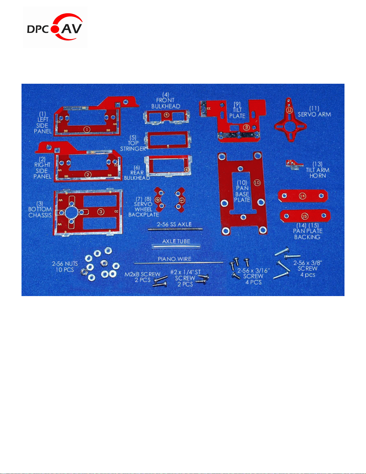
1. Install the top Stringer (item 5) on the chassis at Slots DD. Use a small amount of epoxy or
solder. Use it sparingly since it may be necessary to remove the stringer for repairs or perhaps
to upgrade to the optional 5VDC Voltage Regulator in the future.
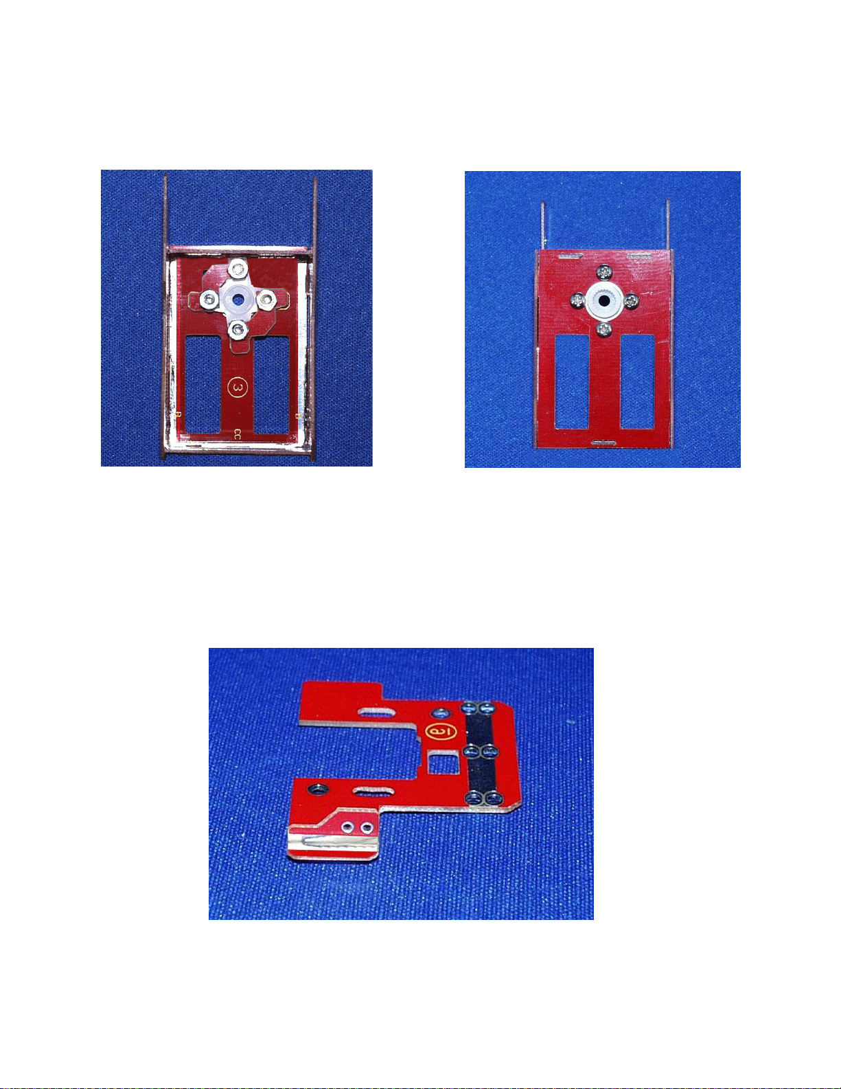
2. Using two 2-56 x 3/8" machine screws and nuts (with Loctite), install the HS-81 pan servo
(with rubber grommets and metal eyelets) to the Base Plate (item 10). Using the retaining
screw supplied with the servo, attach the servo to the chassis mounted servo wheel. Be sure
to install it so that servo center results in a forward looking camera pan position. For best
results, set your R/C transmitter’s EPA/ATV mix for maximum servo travel. Verify that the pan
servo is able to rotate without hitting any chassis obstructions. By the way, the Pan Backing
Plates (items 14 and 15) are used to help strengthen the model where the Pan Base is
installed in it.
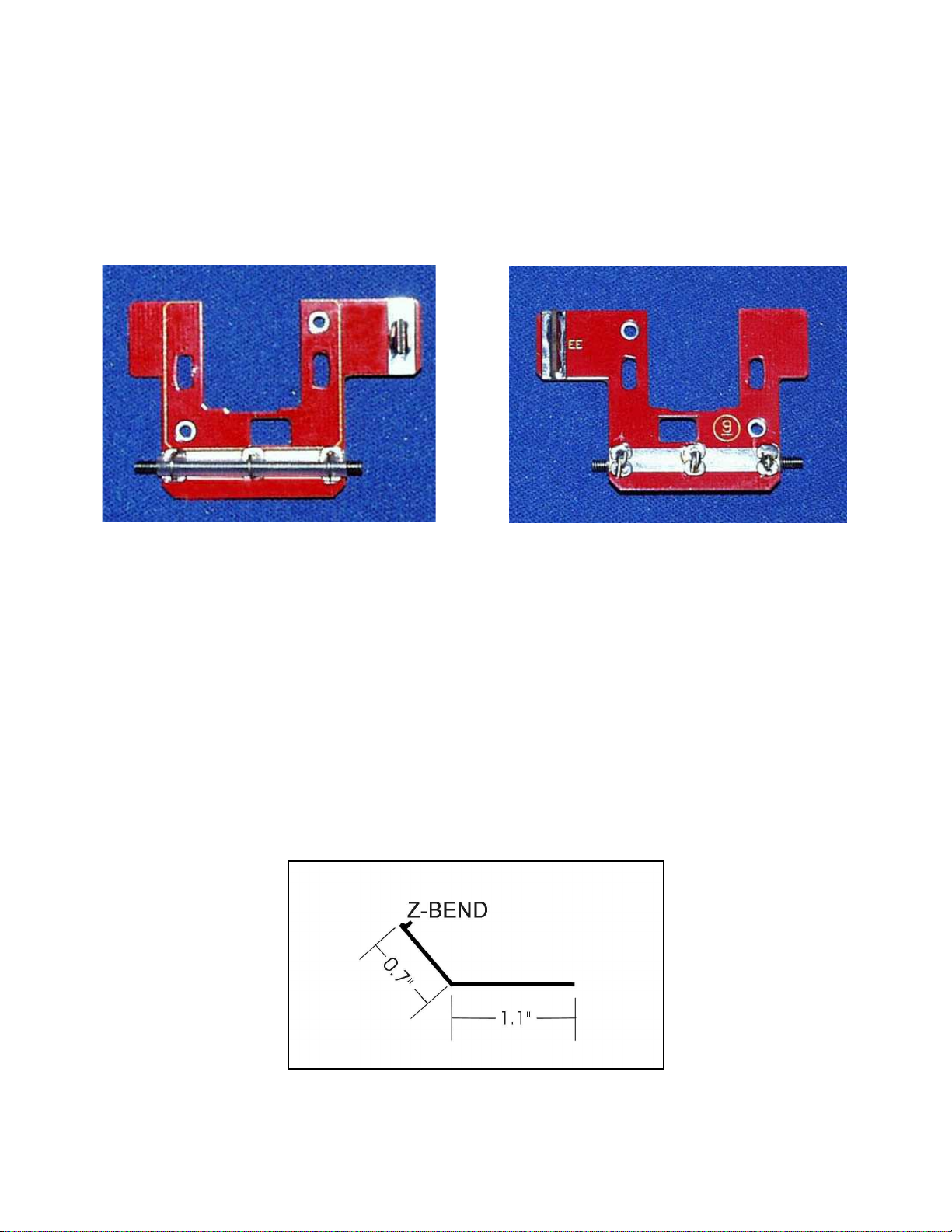
3. While using your R/C transmitter, adjust the tilt linkage for best servo movement. Ensure that
the servo is not allowed to stall or it will be damaged. It will be necessary to adjust your R/C
transmitter’s EPA/ATV mix feature to set the maximum lower and upper travel ranges.
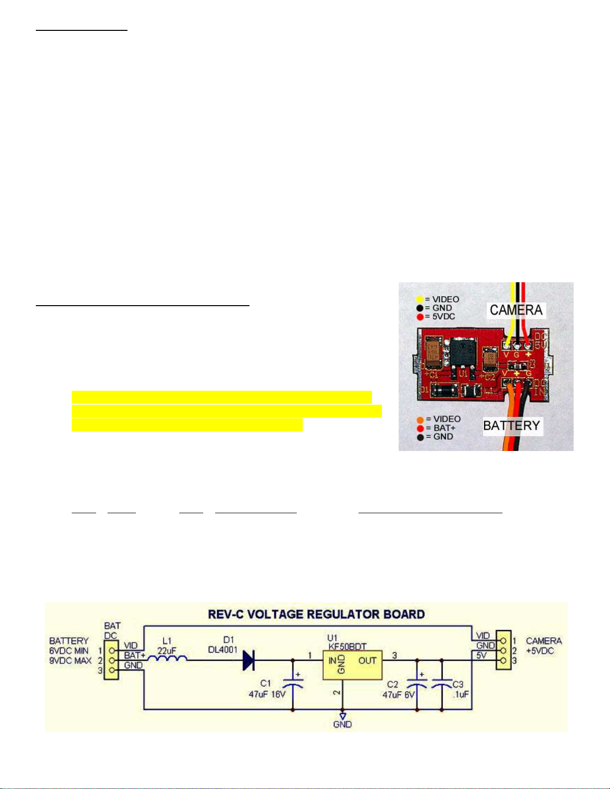
Revision-C Voltage Regulator Option:
The top Stringer (item 5) can be replaced with the optional
5VDC voltage regulator board. It is compatible with the 5-volt
KX-131 (KPC-S226CB) board camera. The input voltage
may range from 6.0VDC to 9.0VDC.
Note: On the Rev-C board, the 3-wire signal order on the
Battery input is NOT the same as the Camera side. Please
consult the photo on the right for full details.
1. The Voltage Regulator requires assembly. It uses SMD
components so advanced soldering skills are needed. The electronic components are
available from mouser.com for about $10.
QTY ITEM REF DESCRIPTION MOUSER PART NUMBER
1 .1uF C3 Capacitor 80-C0805C104J5R
1 47uF 6V C2 Capacitor 80-T491B476K006
1 47uF 16V C1 Capacitor 80-T491C476K016
1 22uH L1 Inductor 80-CBC3225T220MRK
1 DL4001 D1 Diode 833-DL4001-TP
1 KF50BDT U1 LDO VREG IC, 5V 511-KF50BDT
Table of contents
Popular Control Unit manuals by other brands

Gema
Gema OptiStar CG06 Operating instructions and spare parts list

Ublox
Ublox ZOE-M8 Series Hardware Integration Manual

Keyautomation
Keyautomation BOXLED Instructions and warnings for installation and use

mr. steam
mr. steam TEMPO/PLUS owner's manual

Thomas Dudley
Thomas Dudley DUDLEY PINTO quick start guide

TECH FASS
TECH FASS MREM 82 MTM-MF user guide