D+H LSC-M Series User manual
Instruction for use
Lift Smoke Control LSC-M
System for Lift Shaft and
Staircase Smoke Vent

01/48
LSC 44-M4
99.823.35 1.2/06/09
Index
1.0 ......................................................................................3
2.0 .......................................................................6
3.0 System Overview .............................................................................................8
4.0 ...................................................................................................15
Lift Shaft Smoke Vent
Introduction to SHEV Systems
Tube System
1.1 Legal Aspects.........................................................................................................................3
1.2 One System many Advantages..............................................................................................4
1.3 Solutions for every Case of Application .................................................................................5
2.1 Details to the Product.............................................................................................................6
2.2 Details about Mounting ..........................................................................................................6
2.3 Safety Notes ..........................................................................................................................6
2.4 Maintenance ..........................................................................................................................7
2.5 Guarantee ..............................................................................................................................7
3.1 Functional Principle................................................................................................................9
3.2 Why Smoke Suction?...........................................................................................................10
3.3 Wiring Plan Lift Shaft............................................................................................................11
3.4
3.5 Cable for D+H Smoke and Heat Vent Systems ...................................................................13
3.6 Line lenghts and Cross sections ..........................................................................................13
3.7 Project Planning of Smoke Suction System.........................................................................14
4.1 Mounting of Tube System ....................................................................................................16
4.2 Mounting of Reflux Valve at Suction Tube End ....................................................................17
4.3 Pipe Clamps.........................................................................................................................18
4.4 Checking of Tube System ....................................................................................................18
4.5 Tube Project Planning Guideline..........................................................................................19
4.6 Suction Openings.................................................................................................................20
4.7 Air Filter LF-AD ....................................................................................................................21
4.8 Free-Blowing Device............................................................................................................22
Wiring Plan Staircase...........................................................................................................12
4.9 Titanus Pipe-Clean...............................................................................................................22

02/48
LSC 44-M4
99.823.35 1.2/06/09
Index
5.0 .......................................................................23Central Appliance LSC 44-M4
5.1 Mounting Place LSC 44-M4 .................................................................................................23
5.2 Inside Design of Control Center...........................................................................................24
5.3 SHEV Control Panel of Type RZN 4404-M VdS ..................................................................25
5.5 .................................................................................27
5.6 .......................................................................................28
5.7 Codification of
5.8 Codification of Lin
5.9 Codification of Control Panel
5.12 LSC-System for ventilating purposes as well.......................................................................33
5.13 Emergency Power Accumulators .........................................................................................33
5.14 Smoke Suction System of Type MICRO-SENS ..................................................................34
5.16 Central Module LSM 44 .......................................................................................................36
5.17 View motherboard LSM 44...................................................................................................36
5.20 Connection Signalling Lift / External Signals .......................................................................38
5.21 Connection BMS/ RM/ RT....................................................................................................39
5.22 Connection REM/ LT/ MOT/ BZ/ BL .....................................................................................40
6.1 Louvre Drive.........................................................................................................................41
6.2 Domelight.............................................................................................................................41
6.3 Informations for Mounting of Louvres / Domelight ...............................................................42
6.4 Display Panel EF 43-LSC ....................................................................................................42
6.5 Key-operated vent button SLT 42 ........................................................................................43
6.7 Smoke vent button RT 43-H-LSC ........................................................................................46
6.8 Smoke vent button RT 43-H/-N............................................................................................47
6.10 Flashing light BL 41..............................................................................................................48
6.11 General display panel SF 43................................................................................................48
5.4 View motherboard RZN 4404-M VdS...................................................................................26
Standard Connection with RT 43-H/-N
Parallel Connection of RT 43-H/-N
Group 1 and 2 ..............................................................................................29
e 1 and 2 .................................................................................................30
...............................................................................................31
5.10 Factory preset of the DIP-Switch .........................................................................................32
5.11 Delivery Condition................................................................................................................32
5.15 Plug and Play-Initiation-Airflow Alignment ...........................................................................35
5.18 DIP-Switch S1......................................................................................................................37
5.19 DIP-Switch S2......................................................................................................................37
6.6 Fire detector FO 1362.....................................................................................................44-45
6.9 Alarm Series B/SE 24 ..........................................................................................................48
6.0 Smoke Vent Device / Connecting Elements ................................................41
®

1.0
1.1
03/48
LSC 44-M4
99.823.35 1.2/06/09
Lift Shaft Smoke Vent
The State Building Regulations demand, that
smoke vent in lift shafts is ensured in case of fire. By
the Energy Saving Regulation EnEV is
simultaneously demanded, that building external
areas must be constructed in such a way, that they
are permanent air-tight according to the state of the
art.
With LSC D+H offers a special system, which will
provide smoke vent of lift shafts in case of fire by
© 2009 D+H MechatronicAG,Ammersbek,
Rights to technical modifications reserved.
All sizes in millimetre.
Observe protection mark ISO 160 16!
For details see document O00110!
All trade marks used in this form are unreserved
subject to the respective valid trademark right and
possessory right of the respective owner. By
omission of an express marking of the trade name
shall not be given the impression, that the
tradename was not protected by a third party.
Legal Aspects
Legal Aspects
using electric motor controlled louvres, windows or
domelights. The smoke vent flaps, normally closed,
will simultaneously prevent an unnecessary loss of
thermal energy, caused by uncontrolled escaping
of heated air out of the building.
Consequently energy can be saved, ventilation
controlled and smoke vent ensured in case of fire.
Energy Saving Regulation EnEV 10/2007
Operational Safety Regulation
State Building Regulations (LBO)
Lift Guideline 95/16 of the EC
DIN VDI 6017 Behaviour of Lifts in case of Fire
EU guideline DIN V 18599
§ 6 tightness, minimum change of air
(1) Buildings to be erected must be constructed in such a way,
that the heat transfering external area, including the joints, will be
permanently airtight sealed according to the state of art. (…)
energetic valuation of buildings

1.2
04/48
LSC 44-M4
99.823.35 1.2/06/09
One System many Advantages
LSC -Lift Control is an energy-optimized system
for smoke vent and ventilation of lift shafts.
Less draught in a staircase
Early Evacuation
Maintenance direct at Control System
The closed smoke vent openings will lessen the
draught in the staircase and thereby the thermal
comfort will be improved for the user.
Possible whistling sounds will be additionally
avoided, caused by a too high flow of air.
A fire will be already recognized during a fire
formation through the smoke suction system used.
People in the lift can be moved earlier therefore to
the smokefree evacuating level.
The mechanic will not need access to the shaft for
maintenance and cleaning. This will be directly
carried out at the control system.
Lower Thermal Energy Costs
Better Building-Energy Pass
Operators and users must rethink their attitude
towards energy consumption forced by the
continous high oil price as well as generally
increasing energy costs.
The D+H system LSC avoids unnecessary losses
of energy, because a permanent opening in the top
end area of the lift shaft is avoided and with this, an
uncontrolled ventilation of the building will be
prevented.
The result:
Operating expenses will be noticeably reduced.
An optimized thermal insulation will lead as well to
better values in the building-energy pass, which will
be successively prepared for all buildings.
This will have a positive effect on the image of a
building.
From this will result better rentability, not least
because of lower additional costs. This will have a
positive influence on the building value as well.
New!
Integrated Staircase SHEV-System
The flexible SHEV-compact control system
combines simultaneously two functions:
the lift shaft smoke vent
the staircase SHEV-system
Both the requirements will be met with this
intelligent control unit. Both the fire lobbies will be
triggered and monitored separately from one
another.
This system is a compact unit in one housing with
low mounting expenditure and at reasonable
maintenance costs. It has a high degree of
equipment and operating convenience.
-
-

1.3
LSC LSC
05/48
LSC 44-M4
99.823.35 1.2/06/09
Solution for every Application
Detection of a fire will occur by a
in
the
For the a smoke suction system has been
connected by the Lift Smoke Control System
LSC 44-M4. The entire lift shaft will be constantly
monitored through a tube with suction openings,
vertically installed in the lift shaft.
In addition to fire detection in the lift shaft, the
different exit levels will be monitored here by smoke
detectors.
In case of fire (or for ventilation purposes) a smoke
vent opening in the upper area of the lift shaft will be
opened by an electric motor driven drive.
A signal will be additionally given to the lift control,
apart from the release of the SHEV function, which
will run the lift to the predetermined main
evacuating level. This will be usually the main
entrance area.
smoke suction
system in the lift shaft and a smoke detector
staircase.
lift shaft
The integrated will
monitor the adjacent staircase. The smoke
detector, installed at the top end area of the
staircase, will detect the fire smoke in the staircase
and open automatically the smoke vent flap in the
staircase.
The SHEV-function can be triggered additionally as
well via two manually operated SHEV-buttons.The
staircase SHEV-system will run absolutely
independent from the lift shaft smoke vent.
Consequently, fire smoke will be early and reliably
recognized even under difficult conditions.
Evacuating of persons, who possibly are in a lift, is
of particular significance in public buildings, where
a lot of people are coming and going.
SHEV staircase system
2.0
2.2
2.1
2.3
06/48
LSC 44-M4
99.823.35 1.2/06/09
Safety system for protecting human life and
material assets! Once a year functional testing
by a specialist company authorized by the
manufacturer.
Connection, mounting and functional testing by a
specialist company authorized by the
manufacturer.
Green control diodes in the buttons must constantly
lighten, otherwise see “Informations for Starting”.
Repair power failure at once. Instructions of the fire
protection authorities must be always observed.
This SHEV-system has been constructed in
accordance with the latest state of the art and
science. In case of professional mounting and
maintenance it is of high operating safety.
Nevertheless, there can dangers arise from the
product, if by unqualified personell used inexpertly
or not in accordance with the regulations.
Introduction to SHEV Systems
Details about Mounting
Details to the Product
Safety Notes
Danger of Injury or Life!
central appliance
switched idle
Working on the is only allowed, if
this is . This includes distribution
voltage with 230V alternating voltage as well as
emergency power supply with 24V direct voltage.
Only electrical specialist companies are authorized
to install these systems, who have electrical
specialist staff with relevant experiences in
installing danger alarm systems or smoke and heat
vent systems. Only these ones can take on
responsibility for functioning, and can ensure
product liability for the whole system (see product
liability law BGBL.I S.2198 and BGB (bodily injury,
compensation for damage). Therfore, regular
maintenance and checking of functional readiness
is imperative and has to be ensured. These
Smoke and heat vent systems (SHEVs) are very
important elements of structural preventive fire
protection.
Smoke and heat vent systems are appliances of
preventive fire protection. They fulfil important
functions in case of fire as there are: protection of
human life by creating a smokefree layer, by which
escape and rescue routes will be kept free for the
fire brigade. Consequential damages by
conflagration gases are reduced and therefore
considerable material assets are often protected
from destruction. Precondition for this is, that the
system will function absolutely reliable in a case of
fire.
standard requirements are demanded according to
regulations of the DIN, of the Association of
German Insurer against damage of property (VdS)
and the respective local authorities.
In spite of greatest possible care we can not accept
responsibility for this document. All informations
given are no warranted qualification in the sense of
§ 434 BGB.
Current directions of the authorities and the VDE-
regulations must be taken into account during the
entire mounting and installation of the system.
Regulations of the local EVU must be additionally
observed. Furthermore, individual working steps
must be coordinated with the management of
works.
Should special problems arise during mounting or
operation, with which is not extensively enough
dealt with in the operating instructions, so please for
your own safety do not hesitate to consult with the
manufacturer.
Apart from suction tubes with reflux valve and air
recirculation,
nomical maintenance
warranted.
no components will be installed in
the lift shaft! Acceptance by an expert can be can
be only obtained with this precondition as well as
with simple and eco
Unauthorized modifications and alterations at the
SHEV-system are for safety reasons.
This operating instruction must be
before installation.
Keep to the instruction.
not allowed
read through
carefully
Please observe in any case the safety notes.

2.5
2.4
07/48
LSC 44-M4
99.823.35 1.2/06/09
Guarantee
Maintenance
Smoke and heat vent systems must be maintained
at annual intervals by authorized specialist
companies according to DIN 18232 section 2
paragraph 10.2, and VDE 0833 section 1
paragraph 5.3.4 for alarm systems and
manufacturer guidelines.
Renew test badge, keep control book.
The respective current D+H maintenance
instruction is decisive.
D+H authorized expert companies have been
specially trained by D+H for carrying out expertly
this maintenance, and they get automatically the
latest maintenance instructions.
Following tests must be carried out in the course of
maintenance:
- Outside examination/ inspection of system
components
- Measuring of insulation resistances
- Checking of all relevant power supply units
- Functional testing of connected system
components
- Record of competent carrying-out of
maintenance, and designation according
to directions
Once a year by a specialist company, who is
authorized by the appliance manufacturer.
Only regular and professional maintenance
warrants the necessary and permanent
functional safety.
Only authorized specialist companies are allowed
to install and maintain smoke and heat vent
systems and system components, constructed and
distributed by . All
partners belong to these
authorized specialist companies, who regularly
undergo an in-house training to ensure their
qualification and experience.
According to DIN VDE 0108 section 1 paragraph
9.1.1 accumulators for emergency supply (lead
accumulators) must be checked every six months
by a person, who has been introduced to this task,
and once a year, maintenance must be carried out
by specialist companies.
Accumulator types, which are used for
smoke and heat vent systems
must be VdS approved, and must be released by
to use in smoke and heat
vent systems.
According to DIN 18232 section 2 paragraph 10.2
the tests must be put down in an operational book,
which the operator/ building owner must present to
the building supervision authority on request.
This operational book is available at
(Ord.-No.: 68.700.15)
Executed maintenance must be proved by a
maintenance/ and testing
confirmation.
Observe regulations for danger warning systems
VDE 0833, guidelines for electrical systems VdS
2221, DIN 18232 for smoke and heat vent systems,
regulations of the local fire-brigade and of EVU for
connection to mains supply.
D+H Mechatronic AG D+H
Mechatronic AG
D+H
Mechatronic AG
D+H Mechatronic AG
D+H
Mechatronic AG
D+H
Mechatronic AG
You will get guarantee for all D+H products
from date of verified handing over of the system up
to maximal 3 years after date of delivery, when
mounting and starting has been carried out by a
D+H authorized .
2 years
distributor
D+H guarantee is expired, with connection of D+H
components with external systems or with mixing of
D+H products with parts of other manufacturers.

3.0
Rauchabzug
08/48
LSC 44-M4
99.823.35 1.2/06/09
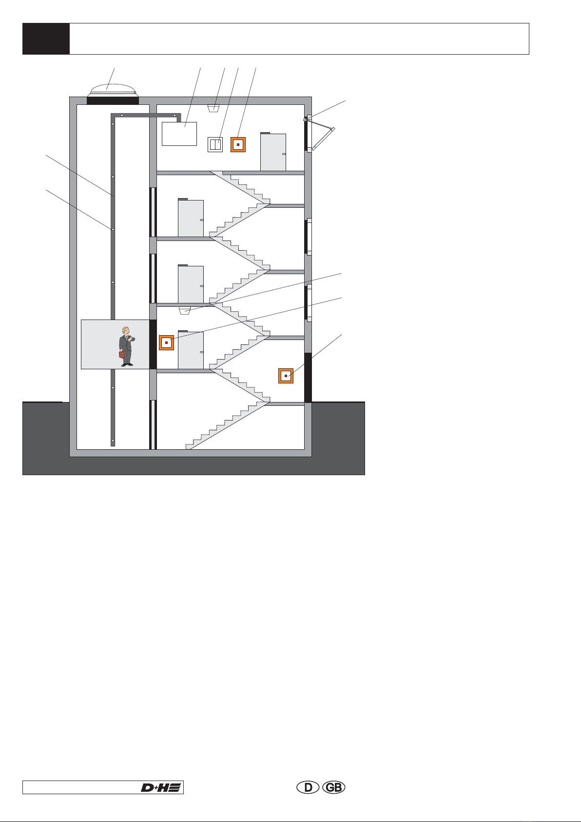
Louvre
window
with drive
in lift shaft
Acoustical + optical
alarm devices *
Smoke detector
*Main evacuating level
Smoke vent button
230V / 50Hz
Mains supply
Lift
shaft
Domelight
with drive
on lift shaft
Tube system
with accessories
<or>
rain detector
VRS 10*
key-operated
ventilation button *
Signal contact
to Lift control
* optional
System Overview
Smoke vent button
RT 43-H-LSC
key-operated
ventilation button *
Smoke
detector
window
with drive
StaircaseLift Shaft
Signal contact to
BMS/ MSR
(measurement
and control)
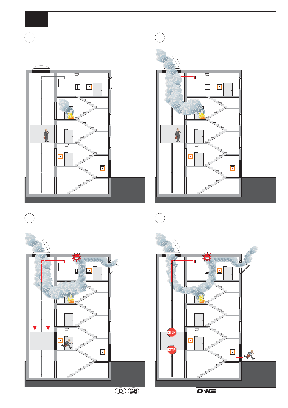
3.1
1 2
3 4
LSC LSC
LSC LSC
09/48
LSC 44-M4
99.823.35 1.2/06/09
Functional Principle
Smoke recognition Opening of the
smoke vent flap
Evacuating travels
of lift car and activation
of the staircase smoke vent
Prevention of
further lift car travels
3.2
LSC
1
2
3456 7
8
9
10
11
10/48
LSC 44-M4
99.823.35 1.2/06/09
Taking samples of air through smoke suction over
the complete height of the lift shaft will prevent
spurious release and allow earlier reliably detecting
of smoke.
Optical smoke detectors ca
e
suction on the individual floor levels and the lift will
be automatically run to the main evacuation level.
No interruption of lift operation necessary during
maintenance.
In the LSC-system is an “extended fire control”
integrated. In this process, the predetermined main
evacuation level will be monitored by an optical
n not be used, because
of whirling caused by the lift car, and danger of dirt
accumulation in the lift shaft, as the danger of
spurious release would be very high.
Smoke will be recorgnized earlier through selectiv
On top of that,
a smoke detector according to the standard DIN
VDE 0833-2 + EN 54-7 in the elevator shaft can not
used, because the inflow of the smoke detector can
not occur freely!
Why Smoke Suction?
1 Suction opening
2 Suction tube
3 Domelight
4 Control panel
5 Smoke detector
6 Ventilation button
7 Smoke vent button
RT 43-N
8 Window drive
9 Smoke detector
10 Smoke vent button
RT 43-LSC
11 Smoke vent button
RT 43-H
smoke detector in front of the landing entrance. If
this smoke detector will release, the lift will be run to
the second evacuation level (will be defined by
customer from the operating authority and the local
fire protection)
Furthermore, SHEV-alarm can be triggered as well
by the smoke detector on the main evacuating level
and the smoke vent flap in the lift shaft will be
opened. Release will be effected in dependence of
the DIP-switch setting (S1) on pcb LSM 44. In case
of SHEV-alarm the electric motor driven opening
drive will be triggered by a re-clocking operation.
With this the drives will be triggered again and again
in regular intervals. Consequently the opening
drives, which may have been blocked first, for
example by icing or sticked seals, will be
nevertheless opened.
The same functionality is ensured also for the
control part of the staircase SHEV-system.

3.3
M
M
JY (St) Y
4x2x0,6
230VAC
24VDC
JY (St) Y
2x2x0,6
JY (St) Y
2x2x0,6
JY (St) Y
2x2x0,6
JY (St) Y
2x2x0,6
JY (St) Y
2x2x0,6
JY (St) Y
2x2x0,6
JY (St) Y
4x2x0,6
JY (St) Y
4x2x0,6
JY (St) Y
4x2x0,6
11/48
LSC 44-M4
99.823.35 1.2/06/09
fire
detector
Key-
operated
vent button
external control
BMS
signal contact
lift
Signal contact
BMS/MSR
smoke
vent button
RT 43-LSC
230V 50Hz
not possible to switch off
control
panel
drive
rain
detector
acoustical signal
transmitter
flashing
light
signal
indicating board
Symbol Description
Wiring Plan Lift Shaft
LSC 44-M4 surface type
600x600x210 (230VAC/ 24VDC)
near the lift shaft
Smoke vent button (RT 43-LSC)
surface 24 VDC circa 1,5m above
upper edge firm flooring (by customer
55mm flush socket)
Vent button 24 VDC (e.g. LT 43) circa
1,2 above upper edge firm flooring (at
flush type by others 55mm flush
socket)
Fire detector 24 VDC
(e.g. FO 1362 or FT 1262)
230V- Power supply
Weak Current Lines
Provide for separate electric circuit.
Mark fuses.
Connecting cable
Install and feed separately from supply mains.
Mark cable and terminal box red.
: NYM-I 3x1.5
Connecting load : RZN 4404-M = 120 VA
flashing
light
acoustical
signal transmitter
signal
indicating board
rain
detector
Drive 24 VDC at smoke vent flap (lines
must end in flush mounted distribution
box, see symbols above).
see cable
wiring table
230VAC
24VDC

3.4
12/48
LSC 44-M4
99.823.35 1.2/06/09
Wiring Plan Staircase
M
JY (St) Y
4x2x0,6
230VAC
24VDC
JY (St) Y
2x2x0,6
JY (St) Y
2x2x0,6
JY (St) Y
2x2x0,6
JY (St) Y
4x2x0,6
key-operated
vent button
smoke
vent button
RT 43-H
smoke
vent button
RT 43-N
see cable
wiring table
to further ones
to further ones
fire
detector
contact
external control
230V 50Hz
not possible to switch off
control
panel
drive
M
Symbol Description
LSC 44-M4 surface type
600x600x210 (230VAC/ 24VDC)
near the lift shaft
Smoke vent button (RT 43-H/N)
surface 24 VDC circa 1,5m above
upper edge firm flooring (by customer
55mm flush socket)
Vent button 24 VDC (e.g. LT 43) circa
1,2 above upper edge firm flooring (at
flush type by others 55mm flush
socket)
230V-Power supply
Weak Current Lines
Provide for separate electric circuit.
Mark fuses.
Connecting cable : NYM-I 3x1.5
Connecting load : RZN 4404-M = 120 VA
Install and feed separately from supply mains.
Mark cable and terminal box red.
Drive 24 VDC at smoke vent flap in the
staircase (lines must end in flush mounted
distribution box, see symbols above).
Rain detector 24VDC (FO 1362) at the top
end of the staircase
230VAC
24VDC

3.5
3.6
LSC 44-M4
13/48
LSC 44-M4
99.823.35 1.2/06/09
Cable for D+H Smoke and Heat Vent Systems
The smoke vent control panel is designed for
opening smoke vent devices, which operate by
thermal ascending force and by automatic fire
recognition devices (thermal detector, smoke
detector), and they release either self-acting or
manual by smoke detectors at an early stage of a
fire, and remain in opened position without further
power consumption. In these cases, functioning
preservation of the electrical line system is required
only at an early stage of fire. Protected wiring is
required with protection against mechanical
damages according to DIN 18232 section 2.7.2.4.
Cable from the smoke vent control panel to
connection of drive (drive lines have a monitoring
wire, in which fire recognition devices (thermal
maximal detector e.g. THE) can be looped-in):
- Safety line, with functional conservation
... E30, according to DIN 4102* or standard
guidelines for line systems MLAR.
Control Cable (Group):
Detector Cables (Line):
Cables through areas not monitored:
The detector cables are monitored for short circuit
and for break.
The opening device is automatically triggered and
opens up in case of fault, when DIP-switch 3 is on
ON.
Smoke vent button cable and cable of automatic
detectors:
- weak current sheathed flexible cable YR 6 x 0.8
or
- house wiring cable IY(ST)Y 4 x 2 x 0.6
An increased time of functioning of the cable can be
required, when drive lines are installed through
building parts, which are not monitored.
- Safety line with functional conservation
... E90, according to DIN 4102* or standard
guidelines for line systems MLAR.
(see supplementary sheet 1 to DIN VDE 0108)
* Notice: No type designation is given for these
cables, because of a large variety on the market.
Please consult your D+H distributor about these.
plain cable length (m) x number of drives
80 **
Line lengths and Cross sections
Number of wires and cross-sections indicated, refer to required lines only. In case of using a line with
earthed conductor (green/ yellow), this one will not be counted in and must not be wired.
*
**
connect in parallel 2 wires for each drive line
only valid for drives with 1A actuating current. Use „160“ for drives with 0,5A actuating current
and „230“ for drives with 0,35Aactuating current.
cross section (mm²) =
Type
drive 0,5A 1 2 345678
1A 1 2 3 4
3 x 1,5mm² 240 120 80 60 48 40 34 30
3 x 2,5mm² 400 200 130 100 80 65 55 50
5 x 2,5mm² 800 400 260 200 160 130 110 100

3.7
14/48
LSC 44-M4
99.823.35 1.2/06/09
Project Planning of Smoke Suction System
Regulations
The following project planning regulation is orientated to the system limitations of TITANUS MICRO-
SENS. In this connection, respective national regulations of the states in the valid version each must be
observed. The project planning must be adapted to these standards.
In Germany
With VdS-Systems
DIN VDE 0833 part 1 and 2 “alarm systems for
fire, burglary and raid”.
Additional provisions for construction of fire alarm
systems, which are issued from the fire
management of the fire brigades, from the
inspection of works or from the building right
authorities, which are only of local validity.
“Guideline for automatic fire alarm systems,
planning and installation” VdS Schadenverhütung
GmbH (VdS 2095).
With CEA-Requirement
With Project Planning Limitations
The CEA-guideline 4022 “Requirements and test
methods for aspirating smoke detectors”
demands a recognition of an airflow disturbance,
if a 50% change of the main airflow arises. In
addition, the size of suction openings has been
laid down on at least 2.0 mm Ø.
The project planning limitations according to
chapter 4.5 have to be taken into account within
this project planning.
Maximum monitoring area of a suction opening
corresponds to the monitoring area of a point
indicator according to the regulations of the
respective national standards.

4.0
Ø 25mm
E
D
C
B
A
10
9
8
7
6
5
4
3
2
1
E
D
C
B
A
10
9
8
7
6
5
4
3
2
1
min.
max.
2m
20m
min.
max.
4m
10m
max.
25cm
15/48
LSC 44-M4
99.823.35 1.2/06/09
ultimate
suction
opening
max. number per tube
system 6 units
max. total tube length
(Ø 25mm) 40m
first suction
opening
first suction
opening
LSC control center
smoke
suction
device
smoke
suction
device
Recirculation in shaft
Shaft
Ceiling
1 x 40 m PVC tube 25x1.9 red
1 x air filter
1 x reflux valve
20 x PVC sleeves
50 x pipe clamps
6 x PVC angles 90°
2 x PVC bends 90°
4 x PVC angles 45°
6 x suction reducing foil
1 x tube of PVC adhesive agent 125 ml
1 x bottle of PVC purifying agent
There is a 25 m Tube-Set optionally
available!
The tube system serves for a defined air sampling
from the monitoring area and consists of different
components.
Tube System
A simplified project planning will be applied in
equipment protection and in conveniences of small
dimensions.
Air Filter
The control panel can also be mounted in the
basement of course, so that the air will be
removed by using suction from the shaft to the
bottom. In this case the reflux valve will be
situated on the lift shaft head.
4.1
1
2
4
3
16/48
LSC 44-M4
99.823.35 1.2/06/09
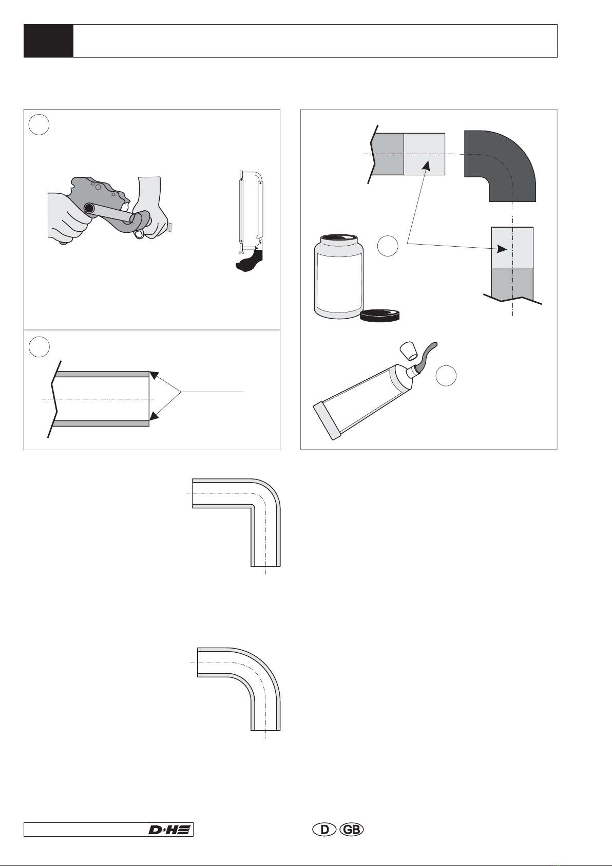
Mounting of Tube System
Burring
fig. 1
fig. 2
Cut tubes to length
(pipe cutter or pipe shears 38mm/
metal cutting saw)
The tube system shall be put together according to the requisition by the project and with observance of
the project planning guidelines.
Burring
Suction tube (PVC)
Suction tube halogen free
(optional available)
R-2519, R-3218, R-4019)
ABSR-2518, ABSR-3220, ABSR-4025
After cleaning, glue
tube street fittings
airtight together!
Clean tube
Street fittings!
Minimize tube lengths and
changes of direction.
(see fig. 1 on the right) have an
extremely high air flow
resistance. Therfore use these
only at places, where they are
inevitable for structural
reasons. If necessary, the tube
length must be reduced in
proportion to the angles used.
(see fig. 2 on the right)
shall be always prefered to
angles. A too high number of
bends and angles will lessen
the velocity of air in the suction
tube and by this, detection time
will be increased.
Angles
Bends
If angles and bends are used, the maximum
total length of the tube system will be reduced.
Standard Value
- a bend corresponds to a straight tube length
of 0,3m.
- an angle corresponds to a straight tube length
of 1,5m.
Tangit
cleaner
Tangit
Adhesive agent
X.x
4.2
1
2
4
3
17/48
LSC 44-M4
99.823.35 1.2/06/09
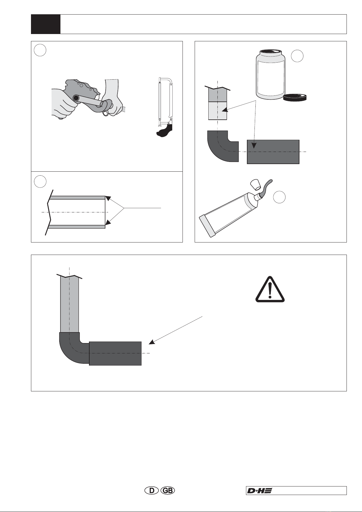
Mounting of Reflux Valve at Suction Tube End
Mount reflux valve,
always horizontally
if used in lift shaft,
that dust and dirt will
not be uncessarily whirled up
in the shaft pit with blowing
through of the tube system.
Cut tubes to length
(pipe cutter or pipe shears 38mm /
metal cutting saw)
Burring
Burring
Suction tube (PVC-red)
Suction tube halogen free
R-2519, R-3218, R-4019
ABSR-2518, ABSR-3220, ABSR-4025
(optional available)
After cleaning,
glue tube street
fittings airtight
together!
Clean tube
street fittings!
Tangit
cleaner
Tangit
Adhesive agent
4.3
4.4
E
D
C
B
A
10
9
8
7
6
5
4
3
2
1
18/48
LSC 44-M4
99.823.35 1.2/06/09
SHEV-control panel
Checking of Tube Systems
- for leakages (e.g. by damages)
- for faulty connections
- for correct project planning of suction openings
- check with critical applications safe detection
with response tests apart from this check,
whether an air throughput is available on the
individual suction openings.
- The ventilator voltage can be infinitely
increased from 9V (standard) up to 13.5V in
order to increase the velocity of air flow in the
tube system in critical areas.
- If the tube system does not meet the project
planning guidelines, as described here,
because of structural facts, it must be
separately calculated by D+H for the respective
conditions.
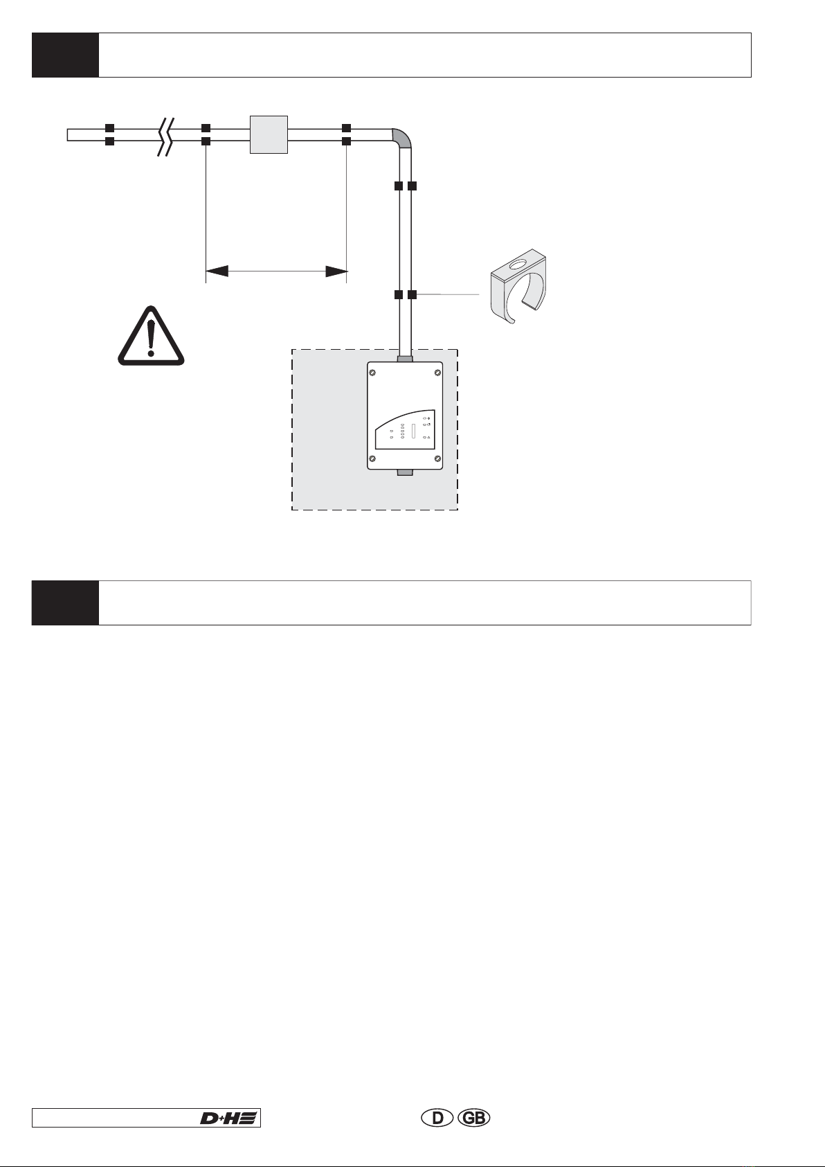
Pipe Clamps
Smoke
suction
device
For the of the tube system,
after tube connection at TITANUS
a type has to be used,
which
Plastic pipe clamps of type NG 23 are
used as standard for installation of the
tube system (Ø 25mm). They do not
allow linear extensions.
first clamp
does not allow linear extension.
MICRO SENS ,
®
(with high
variations
in temperature
max. 30cm)
max. 80cm
Fasten tubes with
pipe clamps without
rubber ply.
Lay tube system firmly.
It must neither hang sagging
nor must it be possible that it
is moved out of place.
Air Filter
This manual suits for next models
1
Table of contents


