DSC FSA-210 User manual

Introduction
The FSA-210 is a 2-wire photoelectric smoke detector with
optional: fixed temperature heat detector, internal piezoelectric
alarm, auxiliary form C relay, and/or remote LED output. Three
version are available: US version (UL), Canadian version (ULC)
and an International version (EU).
Operation
Approximately every 7 to 8 seconds the unit tests for a smoke or
heat alarm condition. During this sequence the unit also per-
forms self diagnostics, and checks for faults. During normal
operation the LED will flash every 50 seconds and the sounder
will not sound.
Smoke Alarm
The smoke detector has a nominal fixed alarm sensitivity (refer
to the Specifications on the last page) and it will go into alarm
when the signal level exceeds the 'alarm' threshold and send
the alarm signal to the control panel. During an alarm the LED
will flash 1/second and the sounder will sound the the evacua-
tion temporal pattern (UL, EU) or continuous beeps (ULC).
Remote Alarm - Interconnection
Multiple detectors (with sounders) can be connected using the
PRM-2W Polarity Reversal Module. When a fire alarm occurs,
the panel will signal the PRM-2W to reverse the polarity of the
2-wire loop. This will activate the sounders of all units con-
nected on the loop. Refer to the PRM-2W/4W Installation
Instructions for installation details.
Smoke - Drift Compensation
The detector automatically compensates for long-term environ-
mentally induced changes to maintain a constant smoke sensi-
tivity. When the drift compensation has reached its high or low
limit of adjustment, the detector will go into the trouble state.
Heat Alarm
The heat detector will go into alarm when the heat signal level
exceeds the heat alarm threshold (135ºF/57ºC); and send the
alarm signal to the control panel. During an alarm the LED will
flash 1/second and the sounder will sound the evacuation tem-
poral pattern (UL, EU) or continuous beeps (ULC).
Installer Instructions
1. Smoke Detector Placement
On smooth ceilings, detectors may be spaced 9.1M (30 feet)
apart as a guide. Other spacing may be required depending on
ceiling height, air movement, the presence of joists, uninsulated
ceilings, etc. Consult National Fire Alarm Code NFPA 72, Chap-
ter 11 CAN/ULC-S553-02 or other appropriate national stan-
dards for installation recommendations.
Do NOT locate smoke detectors at
the top of peaked or gabled ceilings;
the dead air space in these locations
may prevent the unit from detecting
smoke. Avoid areas with turbulent
air flow, (near doors, fans or win-
dows. Rapid air movement around
the detector may prevent smoke
from entering the unit. Do NOT
locate detectors in areas of high
humidity.
Do NOT locate detectors in areas where the temperature rises
above 38ºC (100ºF) or falls below 5ºC (41ºF).
FSA-210 Series Smoke Detector
Installation and Operating Instructions
Read this instruction sheet thoroughly before installation and use of the FSA-210 2-Wire Smoke Detector
P
A
I
N
T
Piezo Sounder
Alignment Marks
LED/Test Button
Place magnet here
DO
N
O
T
Alarm Indications
Condition LED Sounder Relay Alarm
Current
Normal / Sensitivity
in Production
Range
Flash 1/50s OFF Deactivated No
Alarm Smoke/Heat Flash 1/1s Temporal or
Steady Activated Yes
Alarm Restore Flash 1/1s Temporal or
Steady Activated Yes
Remote Alarm Flash 1/50s Temporal or
Steady Deactivated No
Low Power Trouble OFF OFF Deactivated No
Other
Fault / Trouble OFF CHIRP 1/
50s Deactivated No
Test Switch -
Failed OFF CHIRP 1/
50s Deactivated No
Test Switch - Pass Flash 1/1s Temporal or
Steady Activated Yes

Install Smoke detectors in accordance with NFPA 72, Ch. 11.
“Smoke detectors shall be installed outside of each sleeping area in
the immediate vicinity of the bedrooms and on each additional story
of the family living unit, including basements and excluding crawl
spaces and unfinished attics. In new construction, a smoke detector
also shall be installed in each sleeping room.”
2. Mount Smoke Detector Backplate
Mount backplate on standard 4” octag-
onal electrical box using the screws pro-
vided.
NOTE: Power supply must be supplied
from a UL Listed alarm control unit. Install
wiring in accordance with the appropri-
ate national and local electrical codes.
CAUTION:The dust cover protects the
unit when not in service. Remove dust
cover before use.
3. Wiring
Refer to the wiring diagrams in this installation sheet and those
provided in the Installation Manual of the alarm control panel
being used with the unit. Before connecting the unit, prepare the
wires from the electrical box for connection; Do not use frayed or
bent wire.
CAUTION: Do NOT use looped wire under terminals. Break the
wire run, to provide supervision of connections
When wiring is completed, inspect the wiring and correct any
errors before applying power to the unit. When the wiring has
been thoroughly reviewed, neatly insert the wires into the electri-
cal box and secure the unit to the mounting plate.
4. Mounting
Detector Installation:
Position the detector on to the
base plate using the detector and
base plate alignment marks. Press
the detector gently in place while
rotating the detector clockwise
until the detector snaps into
place. Remove the side tab from
the locking tab to lock in place
(optional).
Removal: If the side tab is removed to lock the detector, depress
tab with a small flat blade screwdriver and rotate detector
counter-clockwise until the alignment marks line up. Remove
detector.
5. Test Unit
Initiate test for units without a sounder by placing a magnet near
the LED/Test Button for greater than 5 seconds. Initiate test for
units with a sounder by pressing the test button for greater than
5 seconds.
Alarm activation is indicated by the LED, the sounder, and the
alarm reporting to the Control Panel. If the smoke detectors are
inter-connected using model PRM-2W and a detector is tested,
then all detectors will sound. The detector restores to normal
when the test button is released or when the magnet is removed.
NOTE: Allow a minimum of 20 seconds between test activations.
NOTE: If the detector is in one of the following states when a test
is initiated; it will not enter an alarm state.
1. Compensation trouble.
2. Failure of heat or smoke detector.
3. Other internal faults that could prevent a smoke or heat
alarm.
NOTE: Smoke sensitivity of installed detectors can be measured
without removal or an alarm being generated using the FSD-100
Smoke Detector Test Meter.
Test Unit with FSD-100 Smoke Detector Test Meter
To test the unit using the FSD-100, set the test meter up to read
devices as per the instructions supplied with the test instrument.
Depress the test button (or place the FSD-100 on the outside
edge of the plastics beside the test button to activate the reed
switch on units without sounder) on the smoke detector for 1
second and release.
NOTE: If the test button is held for 5 seconds or longer, an alarm
will be generated.
Move the test meter over the center of the detector, wait until
you hear the test meter beep, remove the unit and the informa-
tion can be immediately reviewed. Please see the instructions sup-
plied with the FSD-100 Smoke Detector Test Meter for more
information.
NOTE: Perform the tests one at a time. Performing simultaneous
tests on multiple detectors may trigger an alarm at the control
panel.
6. Compensation Reset
Cleaning, replacement of the smoke sensor, or other changes
may change the background signal/noise of the detector; this
requires the drift compensation be reset. Compensation trouble is
one of the faults indicated when the LED indicator is OFF while
the sounder is chirping.
1. Remove power from the unit, then press and hold the test but-
ton for 30 seconds to power down unit.
2. Power up unit while pressing the test button.The LED will
flash; when 5 seconds has elapsed. Release the test button
within 1 second after the fifth LED flash.
3. The LED will flash every 8 seconds for 1 minute. When the
detector stops flashing test the detector to verify normal
operation.
Mounting Holes
Locking
Tab
V+
V
9.35-30VDC EOL Device
++
-
++
-
++
-
Relay
NO NC C
LED
OPTIONAL
NOTE: Optional Remote LED
must have a series resistor.
Please see specifications.
Close
Open
Tab Alignment
Marks

Owner’s Instructions
Fire Safety In The Home
Most fires occur in the home, and to minimize this danger, it is rec-
ommended that a household fire safety audit be conducted and a
family escape plan be developed.
Household Fire Safety Audit
1. Are all electrical appliances and outlets in safe condition? Check
for frayed cords, overloaded lighting circuits, etc. If you are
uncertain about the condition of your electrical appliances or
household service, have a professional evaluation.
2. Are all flammable liquids safely stored in closed containers,
and in a cool and well ventilated area? Avoid cleaning the unit
with flammable liquids.
3. Are hazardous materials such as matches out of the reach of
children?
4. Are furnaces and wood burning appliances properly installed,
clean, and in good working order? If in doubt, have a profes-
sional evaluation.
Family Escape Planning
There is often very little time between the detection of a fire and
the time it becomes deadly. Because of this, it is very important
that a family escape plan be developed and rehearsed.
• Include every family member when developing the escape plan.
• Study the possible escape routes from each location within the
house. Since many fires occur at night, give special attention to
the escape routes from sleeping quarters.
• It is essential that escape from a bedroom be possible without
opening the interior door. Consider the following when making
your escape plans:
• Ensure that doors and windows that open to the outside are
easily opened. Ensure that they are not painted shut and that
the locking mechanisms operate smoothly.
• Develop plans for rescue, if opening the exit or using the exit is
too difficult for children, the elderly or handicapped. This plan
includes making sure that those who are to perform the rescue
can promptly hear the fire warning signal.
• If the exit is above the ground level, provide an approved fire
ladder or rope, as well as training in its use.
• Keep exits on the ground level clear. Be sure to remove snow
from exterior patio doors in the winter and that outdoor furni-
ture or equipment does not block exits.
• Have a predetermined assembly point where everyone can be
accounted for; for example, across the street or at a neighbor’s
house.
• Once everyone is out of the house, call the Fire Department.
• A good plan emphasizes a quick escape. Do not investigate first
or attempt to fight the fire, and do not attempt to rescue
belongings or valuables as this takes up time. Once outside, do
not re-enter the house; wait for the Fire Department.
• Write the plan down and rehearse it frequently so that should
an emergency ever arise, everyone will know what to do. Revise
the plan as conditions change; for example, when there are
more or fewer family members in the home or if there are
changes to the house.
• Make sure your fire warning system is operational by conduct-
ing weekly tests. If you are unsure about system operation, con-
tact your smoke detector installer or dealer.
• DSC recommends that you contact your local Fire Department
and request further information on home fire safety and escape
planning. If available, have your local fire prevention officer con-
duct an in-house fire safety inspection.
Testing Your Smoke Detector
Follow the test procedure described here or contact your smoke
detector dealer or installer for testing instructions. DSC recom-
mends that you test the entire alarm system at least once a week
to verify the operation of all system functions.
Units with Sounder - Pushbutton switch
To test the smoke detector, press and hold the test button on the
front of the unit for 5 seconds minimum, the sounder initiates a
clicking noise during this time. When the button is pressed, the
unit’s alarm will sound and an alarm will be sent to the control
panel. When the button is released, the alarm will cease.
Units without Sounder - Magnet activated switch
To test the smoke detector, place a magnet adjacent to the test
button on the front of the unit (see Fig. 1) and hold in place for 5
seconds (minimum). When the magnet is in place, the internal
reed switch will activate and an alarm will be sent to the control
panel. When the magnet is removed, the alarm will cease.
Upon completing the functional testing of the smoke detector,
check the unit’s sensing chamber to ensure proper operation. To
test the sensing chamber, wave a lit cotton wick or punk stick
around the outside of the unit until a generous amount of smoke
enters the sensing chamber or the unit alarms. If the smoke detec-
tor does not function properly, call your smoke detector installer or
dealer for service.
Maintenance
The smoke detector is designed to require minimum maintenance.
If the case becomes dusty, vacuum with a small brush attachment.
If the case is greasy, wipe the case gently with a soft cloth slightly
dampened with soapy water.
Never disassemble the smoke detector; there are no
user serviceable parts inside the unit. Never paint the
unit. Paint may prevent smoke from entering the unit. If
you are planning renovations or repainting, contact
your installer and ask that the unit be temporarily
removed until work is complete.
If the unit is located in an area where it is exposed to high levels of
dust or insects and causes false alarms, it may require service; con-
tact your smoke detector installer or dealer. Testing and mainte-
nance procedures shall be in accordance with CAN/ULC-S552.

Smoke Detector Family Limited Warranty
Digital Security Controls Ltd. warrants that for a period of twelve months from the date of purchase,
the product shall be free of defects in materials and workmanship under normal use and that in fulfill-
ment of any breach of such warranty, Digital Security Controls Ltd. shall, at its option, repair or
replace the defective equipment upon return of the equipment to its repair depot. This warranty
applies only to defects in parts and workmanship and not to damage incurred in shipping or handling,
or damage due to causes beyond the control of Digital Security Controls Ltd. such as lightning, exces-
sive voltage, mechanical shock, water damage, or damage arising out of abuse, alteration or improper
application of the equipment.
The foregoing warranty shall apply only to the original buyer, and is and shall be in lieu of any and all
other warranties, whether expressed or implied and of all other obligations or liabilities on the part of
Digital Security Controls Ltd. Digital Security Controls Ltd. neither assumes, responsibility nor
authorizes any other person purporting to act on its behalf to modify or to change this warranty, nor to
assume for it any other warranty or liability concerning this product.
In no event shall Digital Security Controls Ltd. be liable for any direct, indirect or consequential dam-
ages, loss of anticipated profits, loss of time or any other losses incurred by the buyer in connection
with the purchase, installation or operation or failure of this product.
Smoke Detectors
Smoke detectors that are a part of this system may not properly alert occupants of a fire for a number
of reasons, some of which follow. The smoke detectors may have been improperly installed or posi-
tioned. Smoke may not be able to reach the smoke detectors, such as when the fire is in a chimney,
walls or roofs, or on the other side of closed doors. Smoke detectors may not detect smoke from fires
on another level of the residence or building.
Every fire is different in the amount of smoke produced and the rate of burning. Smoke detectors can-
not sense all types of fires equally well. Smoke detectors may not provide timely warning of fires
caused by carelessness or safety hazards such as smoking in bed, violent explosions, escaping gas,
improper storage of flammable materials, overloaded electrical circuits, children playing with
matches or arson.
Even if the smoke detector operates as intended, there may be circumstances when there is insuffi-
cient warning to allow all occupants to escape in time to avoid injury or death.
Warning: Digital Security Controls Ltd. recommends that the entire system be completely tested on a
regular basis. However, despite frequent testing, and due to, but not limited to, criminal tampering or
electrical disruption, it is possible for this product to fail to perform as expected.
Important Information: Changes or modifications not expressly approved by Digital Security Con-
trols Ltd. could void the user’s authority to operate this equipment.
FCC Compliance Statement
CAUTION: Changes or modifications not expressly approved by DSC could void your authority to use this
equipment.
This equipment has been tested and found to comply with the limits for a Class B digital device, pursuant to
Part 15 of the FCC Rules. These limits are designed to provide reasonable protection against harmful interfer-
ence in a residential installation. This equipment generates, uses and can radiate radio frequency energy and,
if not installed and used in accordance with the instructions, may cause harmful interference to radio commu-
nications. However, there is no guarantee that interference will not occur in a particular installation. If this
equipment does cause harmful interference to radio or television reception, which can be determined by turn-
ing the equipment off and on, the user is encouraged to try to correct the interference by one or more of the
following measures:
• Re-orient the receiving antenna.
• Increase the separation between the equipment and receiver.
• Connect the equipment into an outlet on a circuit different from that to which the receiver is connected.
• Consult the dealer or an experienced radio/television technician for help.
The user may find the following booklet prepared by the FCC useful: “How to Identify and Resolve Radio/
Television Interference Problems”. This booklet is available from the U.S. Government Printing Office,
Washington D.C. 20402, Stock # 004-000-00345-4.
Industry Canada Compliance Statement
This Class B digital apparatus meets all requirements of the Canadian interference-causing equipment regula-
tions.
Cet appareil numérique de la Classe B respecte toutes les exigences de règlement sur le matériel brouilleur du
Canada.
Model Heat Sounder Aux
Relay LED
Output
Max.
Alarm
Current
Draw
FSA-210A, FSA210B, FSA-210C NO NO NO NO 35mA
FSA-210AT, FSA-210BT, FSA-210CT YES NO NO NO 35mA
FSA-210AR, FSA-210BR, FSA-210CR NO NO YES NO 50mA
FSA-210ART, FSA-210BRT,
FSA-210CRT
YES NO YES NO 50mA
FSA-210AS, FSA-210BS, FSA-210CS NO YES NO NO 60mA
FSA-210AST, FSA-210BST,
FSA-210CST
YES YES NO NO 60mA
FSA-210ARS, FSA-210BRS,
FSA-210CRS
NO YES YES NO 75mA
FSA-210ARST, FSA-210BRST,
FSA-210CRST
YES YES YES NO 75mA
FSA-210ALST, FSA-210BLST,
FSA-210CLST
YES YES NO YES 60mA
FSA-210ALRST, FSA-210BLRST,
FSA-210CLRST
YES YES YES YES 75mA
Specifications
Diameter (base) . . . . . . . . . . . . . . . . . . . . . . . . . . . . . . . . . . 5.8in (147mm)
Height (including base) . . . . . . . . . . . . . . . . . . . . . . . . . . . . 2.077in (528mm)
Operating Temperature. . . . . . . . . . . . . . . . . . . . . . . . 32º-100ºF (0º-37.8ºC)
Humidity. . . . . . . . . . . . . . . . . . . . . . . . . . . . . 5%-93% RH, non-condensing
Maximum Operating Voltage Range . . . . . . . . . . . . . . . . . . . . . 9.35 - 30VDC
Maximum Standby Current . . . . . . . . . . . . . . . . . . . . . . . 20
µ
A@12 or 24VDC
Maximum Alarm Current: . . . . . . . . . . . . . . . . . . . . . . . . . . . . . . . . 35-75mA
Smoke Sensitivity ULC. . . . . . . . . . . . . . . . . . . . . . . 2%±0.5%/ft obscuration
Smoke Sensitivity UL . . . . . . . . . . . . . . . . . . . . . . . . 3%±0.8%/ft obscuration
Heat Alarm . . . . . . . . . . . . . . . . . . . . . . . . . . . . . . . . . . . . . . . 135ºF (57ºC)
Sounder Alarm Pattern UL . . . . . . . . . . . . . . . . Evacuation Temporal Pattern
Sounder Alarm Pattern ULC . . . . . . . . . . . . . . . . . . . . . . . Continuous Beeps
Minimum Remote LED Resistance:
12V system. . . . . . . . . . . . . . . . . . . . . . . . . . . . . . . . . . . . . . . 500 Ohm
24V system. . . . . . . . . . . . . . . . . . . . . . . . . . . . . . . . . . . . . . 1000 Ohm
Maximum Remote LED output (if equipped):. . . . . . . . . . . . . . . . . . . . 25mA
Auxiliary Relay Rating (Form C Relay) . . . . . . . . . . . . . 2A @ 30VDC (Resistive)
FSA-210 series compatibility identifier: . . . . . . . . . . . . . . . . . . . . . . . . FS200
Compatible Control Units:
DSC PC1555 with compatibility identifier: . . . . . . . . . . . . . . . . . .PC15-1
DSC PC5010 with compatibility identifier: . . . . . . . . . . . . . . . . . . .PC5-1
DSC PC5015 with compatibility identifier: . . . . . . . . . . . . . . . . . .PC15-1
DSC PC5020 with compatibility identifier: . . . . . . . . . . . . . . . . . . .PC5-2
DSC PC4020 with compatibility identifier: . . . . . . . . . . . . . . . . . . . FM-2
DSC PRM-2W with compatibility identifier: . . . . . . . . . . . . . . . . . . PR200
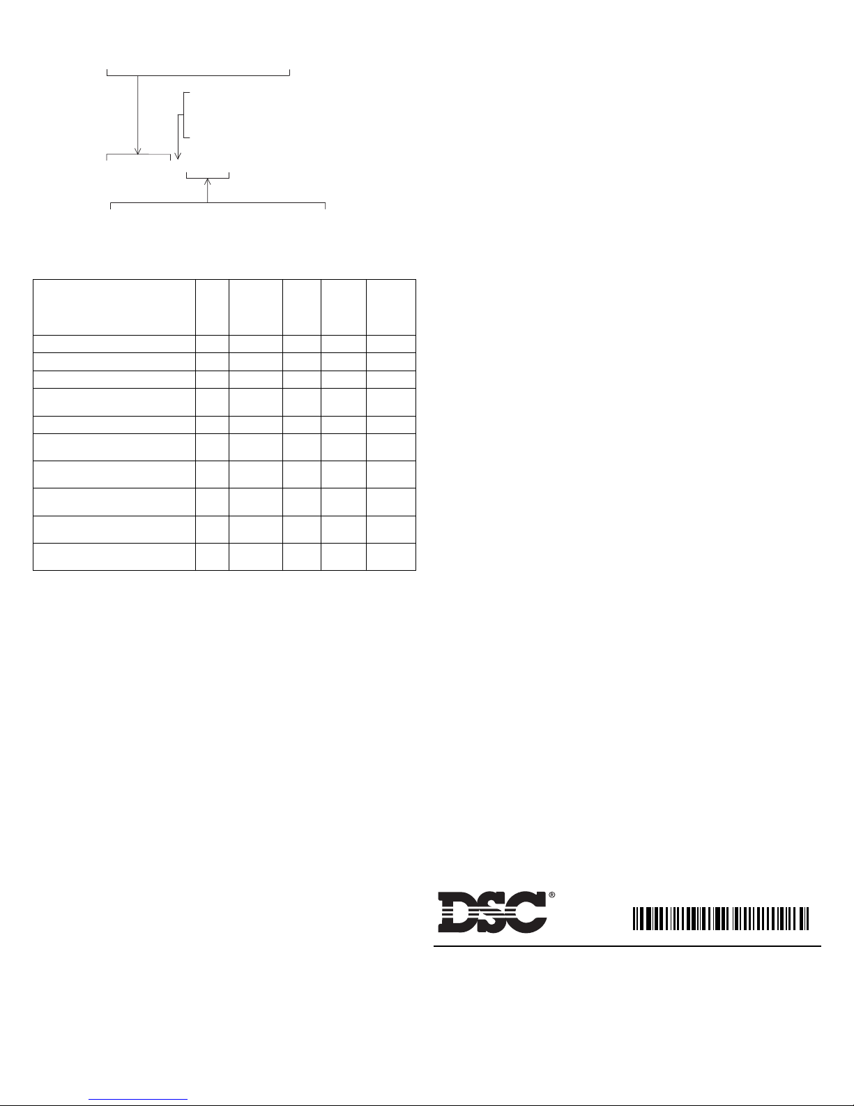
L = Remote LED output
R = Auxiliary Form C Relay
S = Sounder
T = Fixed Temperature Heat Sensor
FSA-210 XYYYY
A = ULC
B = UL
C = EU
2-Wire Smoke Detector Family
29006015R002
©2003 Digital Security Controls
Toronto, Canada • www.dsc.com
Tech Support: 1-800-387-3630 or 905-760-3036
Printed in Canada 29006015 Rev 002
This manual suits for next models
30
Table of contents
Other DSC Smoke Alarm manuals

DSC
DSC PG9936 Serires User manual

DSC
DSC MN-240 series User manual

DSC
DSC AMS-220 Owner's manual

DSC
DSC WS8916 series User manual

DSC
DSC FSB-210 Series User manual

DSC
DSC Meridian WLS906-433 User manual

DSC
DSC WS4926 Series User manual

DSC
DSC WS4916 Series User manual

DSC
DSC FSA-210 Series User manual

DSC
DSC FSA-410A User manual

DSC
DSC WS4916 Series User manual

DSC
DSC Maxsys PC4612 User manual

DSC
DSC WS4913 Series User guide

DSC
DSC FSA-410D Series User manual

DSC
DSC WS4916 Series User manual

DSC
DSC FSD-100 User manual

DSC
DSC PG9933 User manual

DSC
DSC WLS916-433 Series User manual

DSC
DSC WS4936EU User manual

DSC
DSC FSD-100 User manual