Smartek NUBI 4.0 User manual
NB40S1
REV 01 – Nov. 2018 - ENGLISH
NUBI 4.0
Model: NB40S1
Power supply: 12V C
PIR: NO
Thank you for purchasing NUBI 4.0, the intelligent smoke
screen security device able to be connected to any burglar
alarm system in new or existing systems.
OPERATIONAL OVERVIEW
The device is powered from 10V C to 15V C, usually
supplied by the alarm control panel, the consumption is
less than 1mW. NUBI 4.0 does not require any additional
energy from the external power supply when the smoke
cartridge is ignited, as this energy has already been stored
on the motherboard. This ensures the ignition of the
cartridge in any power condition and the guarantee of not
having any overload on the power supply even in case of
simultaneous triggering of many NUBI 4.0 devices.
NUBI 4.0 efficiently protects volumes up to 100 m3. The
smoke generated by NUBI 4.0 is based on incense and
does not produce toxic atmosphere as tested according to
the TLV-STEL directive EU 2017/164 and ACGIH. After use
the room must be ventilated before staying there.
This version of NUBI 4.0 has no integrated PIR, it has only
the input to trigger the immediate smoke delivery.
The polarity of this input and its logic can be easily
configured using IP switches to interface NUBI 4.0 with
anyburglar panel or command device.
The box opening is detected with a tamper switch, its clean
contact can be connected to the burglar panel.
The smoke cartridge works only once, the smoke
emission, when triggered, can no longer be interrupted.
The smoke cartridge replacement is very easy, each spare
cartridge is provided with a special board soldered on its
wires to be easily plugged on the proper motherboard
connector.
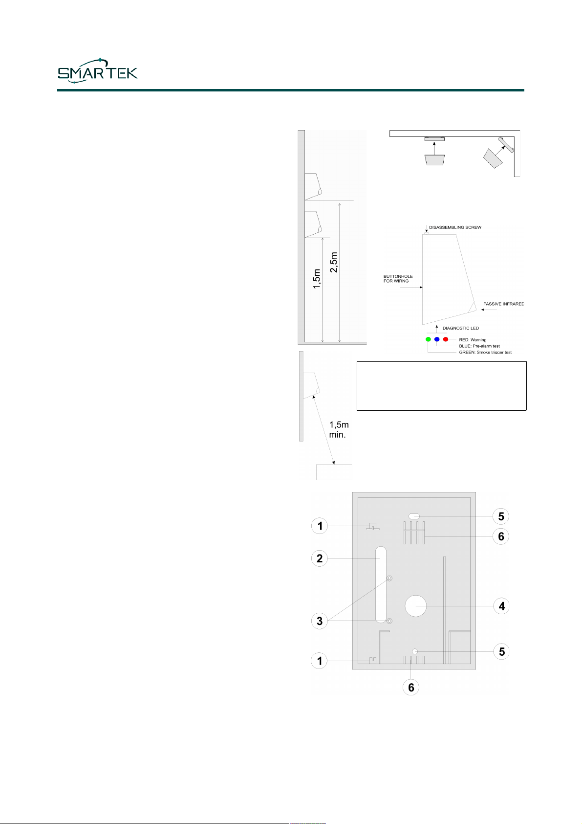
INSTALLATION
NUBI 4.0 can be easily installed on the
wall or even in a corner at a height
between 150 and 250 cm.
WARNING
o not insert any obstacle at a distance
of less than 1.5 meters from the smoke
outlet hole.
The best performance is achieved when
the jet of smoke coming out from NUBI 4.0
directly hits the floor, in this way the smoke
will cool and spread better.
After opening the top cover, remove the
motherboard to fix the lower part of the box on the wall.
1 Motherboard rails
2 Cabling wire buttonhole
3 Internal siren fixing spacers
4 Internal siren sound outlet hole
5 evice fixing holes
6 Smoke cartridge supports
NB40S1
REV 01 – Nov. 2018 - ENGLISH
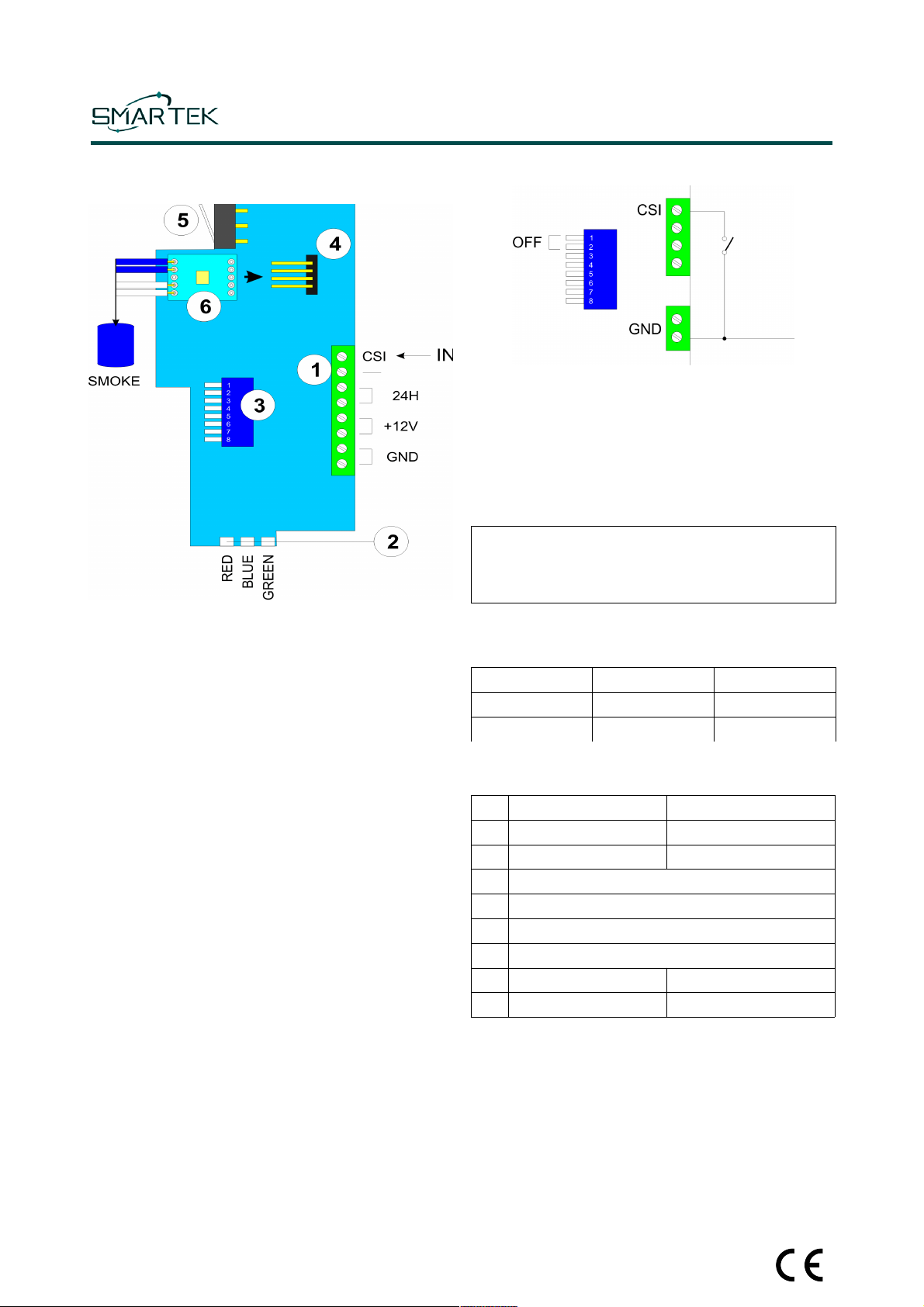
MAINBOARD
1) Main connector
2) iagnostic LE s
3) IP Switch
4) Smoke cartridge connector
5) Tamper switch
6) Validation board provided with smoke cartridge
MAIN CONNECTOR
GN : Ground power supply
+12V: +10..15V C power supply
24H Tamper clear contact
CSI Immediate smoke delivery (INPUT)
UNDERVOLTAGE ROTECTION
NUBI 4.0 is protected against under voltage. When the
power supply falls below the 10V threshold, the smoke
emission will be inhibited.
This function prevents unwanted smoke emissions when
NUBI 4.0 and the alarm panel use the same power supply
and the alarm panel causes unwanted commands due to a
low supply voltage.
This could happen during a power failure that lasts a long
time and drains the battery below the 10V limit.
INPUTS INTERFACE
When the IP Switches 1 and 2 are set to OFF, NUBI
inputs CSI will become active when switched to GN , in
this case it will trigger the immediate smoke delivery.
With IP SW1, the input reference can be changed from
GN to + 12V (+ VCC). Using SW2, the input logic can be
switched from normally open to normally closed, in this
case the smoke emission will be activated when the input
is opened.
In the event that the inputs are not driven with a clean
contact to GN , never appl a voltage higher than
+VCC to the input which would irreversibly damage the
electronic circuit.
For any kind of interface, the inputs voltage thresholds are
the followed:
Min V Max V
Level 0 GN 2,0V
Level 1 8,0V +VCC
DIP SWITCHES
DIP OFF ON
1Input driven to GN Input driven to +12V (+VCC)
2CSI input normally open CSI input normally closed
3Not used
4Not used
5Not used
6Not used
7Operating mode Test mode
8Tamper enabled Tamper disabled

NB40S1
REV 01 – Nov. 2018 - ENGLISH
DIAGNOSTIC LEDs
iagnostic LE s are active only in test mode.
BLUE Flash when NUBI is in test mode.
GREEN Flash when the smoke cartridge is triggered.
RE Warnings.
24H OUTPUT
24H output is a clear contact normally closed when the
NUBI 4.0 box is closed, it will open when the box will be
opened. When the SW8 is set to ON, tamper output is
disabled (output is always closed).
TEST MODE
Set the IP SW7 to ON to activate the test mode. As soon
as the device enters test mode, all the LE s and the
buzzer will flash 8 times. If the voltage is below 10V, the
red LE and the buzzer will remains ON, otherwise the
green LE will flash one time, then the smoke cartridge
will be tested. When it is empty the red LE and the
buzzer will light up and the green LE on the validation
board will be OFF. When the smoke cartridge is not empty
the green LE on validation board will flash, the test will
continue and the BLUE led will flash slowly, one time each
second, to indicate the test mode is activated.
When, according to the programming mode of SW1 and
SW2, the CSI input will trigger the smoke delivery, the
GREEN LE will flash for 1 second to indicate the
simulation of the activation of the smoke cartridge.
Remember to activate the operating mode (DIP SW7
OFF) at the end of testing.
SMOKE CARTRIDGE REPLACEMENT
When a smoke cartridge is empty, it must be replaced with
a new one. The smoke cartridge is supplied with the
validation card welded to the ends of the wires. Only in test
mode (SW7 ON) the green LE on validation board will
flash when the cartridge is full, OFF when it is empty and
needs to be replaced.
Remove the power suppl and wait at least 3
minutes before replacing the smoke cartridge.
1) Remove from the motherboard the old validation
card soldered onto the wires of the empty smoke
cartridge.
2) Insert the new validation card soldered onto the
wires of the new cartridge.
COMMISSIONING
We advise to perform a test (see previous chapter Test
mode) before perform a definitive commissioning of the
device. Set the IP SW7 to OFF to switch in operating
mode. We advise to remove the adhesive that protects
smoke exit hole of the smoke cartridge.
WARNING PROCEDURE TO PREVENT SMOKE
EMISSION AT THE POWER UP
uring the first 30 minutes after power the device, there
is a special function to prevent unwanted smoke
emissions, for example due to wiring errors.
When the smoke activation condition occurs during this
time, instead of immediately emitting smoke, a warning
procedure starts and the red LE flashes for 120
seconds.
It will be possible to stop the activation by opening the
box and setting the IP SW7 to ON or, in case of
difficulty, it will also be possible to unplug the smoke
cartridge validation card from the motherboard.
If this warning procedure is not interrupted, at the end of
the 120 seconds we will have the emission of smoke.
Each time this warning procedure is activated, the 30-
minute timer is regenerated to allow an additional 30
minutes of test time.
MAINTENANCE
We recommend replacing the smoke capsule every 5
years using only the original replacement.
WARRANTY
SMARTEK s.r.l. It guarantees its products against all
manufacturing defects for a period of 30 months from the
production date shown on the label.
RECOMMENDATIONS
Before leaving, ventilate the rooms thoroughly after the
smoke has been delivered.
TECHNICAL SPECIFICATIONS
Power supply From 10 to 15V C
< 1mW
Size 12cm x 17cm x 14cm
Saturable volume 100m3
Weight 760g
Smoke average delivery time 25sec
Operating temperature From 0°C to +45°C
Storage temperature From -20°C to +55°C
Maximum relative humidity 70%
Inputs CSI – Immediate action
Outputs 24H – Tamper
This manual suits for next models
1
Other Smartek Smoke Alarm manuals


