8
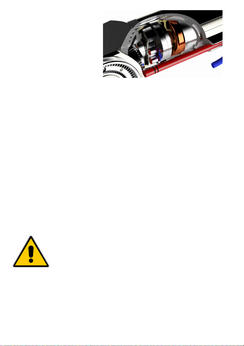
Further to this, the Beluga SXM-V
has a completely redeveloped overload-
coupling that transfers the supplied
torque through a statically sealed wall.
Thus there is no need for the contact seal
that has previously been required. This
drastically increases the service life of the
entire machine and the maintenance
intervals are significantly longer. The
overload coupling is also much more
elastic than traditional systems and does
not have a slip-and-stick effect. Since the
torque is transferred without contact, no
wear at all occurs on the coupling. The activation of the coupling is also monitored by a sensor. When
triggered, this determines whether the motor is turning and the gearbox is standing, and the motor is
immediately stopped. This protects the operator and the machine against excessive heating of the
coupling. After the machine is successfully stopped,, it can be set in motion again by activating the start
lever again.
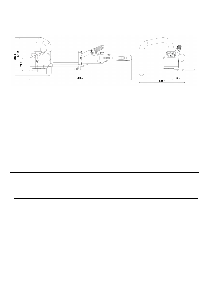
2.2 Applications
The drive units BELUGA and the related Powerboxes can be used according to the data attached to the
information plate. When you are using custom-built machines, the details on the quotation and the order
confirmation also apply.
The drive units and the Powerboxes are essentially Class I appliances, only this guarantees the full high-
quality protection of the residual current circuit breaker.
When suitable saw blades and drill bits are used, a wide range of materials can be cut:
- Concrete (even with strong reinforcement)
- Sandstone and limestone
- All building materials for solid walls
- Asphalt road surfacing
The machines must be connected to the Powerbox RX/SX 12.
2.3 Safety
Warning
Before commissioning, check that the mains voltage and frequency match the
data given on the information plate. ± 5 % voltage and/or ± 2 % frequency
deviation are permitted. Repairs may only be performed by suitably qualified
staff based on their training and experience.
Pay particular attention to:
-the technical data and information on the permitted use (commissioning, standard operating
conditions), which are included e.g. in the catalogue, the operating manual, the information plate
details, and other product information.
-the relevant accident prevention regulations
-the correct use of tools
-the use of personal protective equipment