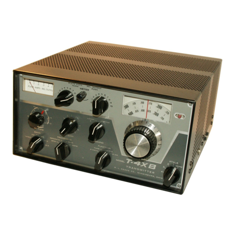
DRAKE T-4B User manual

INSTRUCTION
MANUAL
Z
ddd.
LL
ldams
:
RICE
OF
INSTRUCTION
MANUAL
$2.00
AL.
DFA
KE
COMPANY
-
MIAMISBURG,
OHIO

STANDARD
WARRANTY
R,
Le
DRAKE
COMPANY
warrants
each
new
radio
product
manufactured
by
it
to
be
free
from
defective
material
and
workmanship
and
agrees
to
remedy
any
such
defect
or
to
furnish
a
new
part
in
exchange
for
any
part
of
any
unit
of
its
manufacture
which
under
normal
installation,
use,
and
service
discloses
such
defect,
provided
the
unit
is
de-
livered
by
the
owner
to
us
or
to
our
authorized
radio
dealer
or
wholesaler
from
whom
purchased,
intact,
for
our
examination,
with
all
transportation
charges
prepaid
to
our
factory,
within
ninety
days
from
the
date
of
sale
to
original
purchaser
and
provided
that
such
examination
discloses
in
our
judgement
that
it
is
thus
defective.
Should
a
malfunction
be
suspected,
write
in
detail
to
our
Service
Department
for
suggestions
concerning
the
operation,
repair
or
return
of
your
unit
if
it
should
prove
necessary.
This
warranty
does
not
extend
to
any
of
our
radio
products
which
have
been
subjected
to
misuse,
neglect,
accident,
incorrect
wiring
not
our
own,
improper
installation,
or
to
use
in
violation
of
instructions
furnished
by
us,
nor
extend
to
units
which
have
been
repaired
or
altered
outside
our
factory,
nor
in
cases
where
the
serial
number
thereof
has
been
removed,
defaced
or
changed,
nor
to
units
used
with
accessories
not
manufactured
or
recommended
by
us.
Any
part
of
a
unit
approved
for
remedy
or
exchange
hereunder
will
be
remedied
or
exchanged
by
the
authorized
radio
dealer
or
wholesaler
without
charge
to
the
owner.
This
warranty
is
in
lieu
of
all
other
warranties
expressed
or
implied
and
no
representative
or
person
is
authorized
to
assume
for
us
any
other
liability
in
connection
with
the
sale
of
our
radio
products.
The
R.
L.
DRAKE
COMPANY
reserves
the
right
to
make
any
improvements
to
its
products
which
it
may
deem
desirable
without
obligating
itself
to
install
such
improvements
in
its
previously
manufactured
products.
Ro
Le
DRAKE
COMPANY
MIAMISBURG,
OHIO
45342

TABLE
GENERAL
SPECIFICATIONS---------------
MODES
OF
OPERATION-------------------
CONTROLS
&
JACKS---------------------
POWER
REQUIREMENTS-~-----------------
POWER
SUPPLY
SPECIFICATIONS----------
TUBES
&
SEMICONDUCTOR
COMPLEMENT----~-
Il.
IIt.
IV.
DESCRIPTION---------------------
INSTALLATION
INSTRUCTIONS
-------
A.
Unpacking
B.
Location
C.
Power
Requirements
D.
Antenna
Requirements
E.
Receiver
Muting
F.
Receiver
Antenna
Switching
G.
Anti-Vox
&
Sidetone
H.
R-4
Injection
I.
Microphone
Requirements
J.
Speaker
K.
Ground
Requirements
L.
Linear
Amplifier
Connection
CONTROL
FUNCTIONS---------------
A.
Front
Controls
B.
Side
Controls
&
Jacks
C.
Rear
Connections
&
Controls
D.
Inside
Controls
TUNING
PROCEDURE------------7777
A.
Bias
Adjustment
B.
Tune
Up
on
Desired
Band
C.
Carrier
Balance
Adjustment
D.
Transceive
Alignment
OPERATION---------erre-
rrr
rrr
A.
Voice
Controlled
&
PIT
Operation
on
SSB
B.
CW
Operation
Cc.
AM
Operation
D.
Spotting
E.
Transceiving
F.
Operation
on
Accessory
Tuneable
Ranges
G.
Crystal
Controlled
Operation
H.
Operation
with
a
Linear
Amplifier
I.
RTTY
Operation
with
an
R-4/R-4A/R-4B
and
T-4B
DADUNUNMUNUNPR
HLH
OF
CONTENTS
PAGE
VI.
THEORY
OF
OPERATION------------~-
27
VII.
SERVICE
DATA---------<c-r-er-
A>
29
A.
Removing
Top
Cover
29
B.
Removing
Bottom
Cover
29
C.
Tube
Replacement
29
D.
Trouble-Shooting
29
VIII.ALIGNMENT
INSTRUCTIONS
---------
34
A.
Adjustment
of
RF
&
34
Mixer
Stages
B.
Carrier
Osc.,
Filter
Match
35
&
Balanced
Modulator
C.
Neutralizing
Final
Amp.
35
IX.
AC-4
POWER
SUPPLY--------<-c---"
37
X.
DC-4
POWER
SUPPLY------------77
38
CHARTS
&
ILLUSTRATIONS
MILA
SS
OS
Ee
eee
PAGE
Microphone
Wiring
Dwg.----
6
Connecting
T-4B
to
R-4B---
7
Connecting
T-4B
to
a
LA---
7
Connecting
T-4B
to
a------
8
Receiver.
-----------r
one
8
Viewing
Angle
Options-----
8
Side
View
T-4B------------
12
Rear
View
T-4B------------
12
TR-448
Illustration-------
23
RF
Tune
Curves------------
24
FSK
Circuits--------------
25
Block
Diagram
T-4B--------
26
Resistance
Chart----------
30
Voltage
Chart-------------
30
Top
View
T-4B-------------
31
Bottom
View
T-4B----------
32
8
Pole
Crystal
Atten.-----
20
C
t
ey
Chart
HCO
Sematic----
oe
en
es
37
DC-4
Schematic------------
39
T-4B
Schematic--(fold
out
page)

GENERAL
SPECIFICATIONS
Frequency
Coverage:
3.0
to
30
MHz
except
5.0
to
6.0
MHz.
11.0
to
11.5
MHz
used
crystal
control
only.
In
addition
either
1.8
to
2.3
or
2.0
to
3.0
MHz
will
be
included.
Frequency
Control:
By
tuneable
oscillator
and
range
crystals
in
R-4,
R-4A
or
R-4B
Receiver
or
by
one
of
the
ten
crystals
available
by
front
panel
switch.
Crystals
must
be
ordered
separately
specifying
transmitting
frequency
desired.
A
frequency
control
switch
is
provided
on
front
panel
to
select
tuneable
tran-
sceive,
crystal
control
transceive,
or
tuneable
receive
with
crystal
control
transmit.
Stability:
Less
than
100
cycles
after
warm
up.
Less
than
100
cycles
with
10%
change
in
line
voltage.
MODES
OF
OPERATION
SSB:
Upper
or
lower
sideband
on
all
bands.
Vox
or
Push-to-Talk.
CW:
Grid-block
keying.
Vox
circuit
is
keyed
for
automatic
transmit
receive
switching.
Sidetone
oscillator
is
keyed
for
monitoring.
Shifted
carrier
system
has
no
spurious
output.
AM:
Controlled
carrier
AM
modulation
is
built
in.
This
system
is
compatible
with
SSB
linear
amplifiers.
Vox
or
Push-to-Talk.
RITY:
Adaptable
to
RTTY
operation.
SIDEBAND
SUPPRESSION:
60
dB
or
bettero
CARRIER
SUPPRESSION:
60
dB
or
better.
AVERAGE
DISTORTION
PRODUCTS:
In
excess
of
30
dB
down.
FREQUENCY
RESPONSE:
Through
the
filter,
350
to
2750
cycles
at
6
dB
down.
INPUT
POWER:
SSB
and
AM
-
200
watts
PEP.
CW
=
200
watts.
OUTPUT
POWER:
SSB
and
AM
-
120
watts
PEP
or
more.
CW
-
120
watts
or
more.
OUTPUT
IMPEDANCE?
Nominal
52
ohms
adjustable
with
pi-network.
(SWR
should
be
2:1
or
less).
MICROPHONE
INPUT:
High
impedance.
AGC:
Operates
on
SSB
to
prevent
flat
topping
due
to
overdrive.
1.

CONTROLS
AND
JACKS
FRONT:
Crystal
Switch,
Function
Switch,
Sideband
Selector,
Band
Switch,
RF
Tune,
Gain,
Plate
Tuning,
Plate
Loading,
Fre-
quency
Control
Switch,
Plate
Current/Relative
Output
Meter
Switch
and
Crystal
Control
Indicator
Light.
SIDE:
Anti-Vox/Sidetone
Gain,
Vox
Gain,
Microphone
Jack,
Xtal
Access
Door
with
Frequency
Chart.
REAR:
Power
Connector,
Mute
Jack,
Receiver
Antenna
Jack,
Anti-Vox/
Sidetone
Jack,
Key
Jack,
Antenna
Connector,
Ground
Post,
Speaker,
R-4/R-4A/R-4B
Injection
Jack,
and
Vox
Delay
Potentiometer.
INSIDE:
Carrier
Balance
Control.
DIMENSIONS:
54"
high,
10-3/4"
wide,
cabinet
depth
11-5/8",
overall
length
12-1/4",
WEIGHT:
12
pounds,
7
ounces.
POWER
REQUIREMENTS
:
Model
AC-4
Power
Supply
-
operates
on
120
or
240
V.
50/60
Hz.
or
Model
DC-4
Power
Supply
-
operates
on
12 V.
DC
negative
ground
and
has
120
V.
300
-
400
Hz
output
to
operate
R-4/R-4A/R-4B
Receivers.
POWER
SUPPLY
SPECIFICATIONS:
1.
650
volts
at
200
ma
average
and
330
ma
maximum
with
10%
regulation
from
66
ma
to
330
ma
and
maximum
ripple
of
less
than
1%.
2.
250
volts
at
120
ma
with
10%
regulation
from
82
ma
to
120
ma.
This
includes
the
effect
of
the
650
volt
supply
change
if
both
voltages
are
obtained
from
the
same
transformer.
.
Maximum
ripple
must
be
less
than
1/4%.
3.
-45
to
-65
V
DC
adjustable
filtered
bias
into
33
K
ohm
load.
4.
12.6
volts
AC
or
DC
at
3
amps.
TUBES
AND
SEMICONDUCTOR
COMPLEMENT
NUMBER
FUNCTION
12BA6
IF
Amplifier
12BY7
Driver
2
-
6JB6
Power
Amplifier
12AX7
Mic.
Amp/Sidetone
Osc.
6EV7
VOX
Amp.
6HS6
Buffer
6AU6
AM
Modulator
12AX7
AGC
Amp.
Carrier
Osc.
OA2
Voltage
Regulator
3
-
1N483A
VOX
&
Anti-Vox
Rectifiers
4
-
1N541
Balanced
Modulator
1N483A
Trigger
1N270
Output
Meter
Detector
6AU6
Mixer
1N483A
Sidetone
Keyer
MPF
-
102
Xtal
Oscillator

I.
DESCRIPTION
The
R L
DRAKE
Model
T-4B
Transmitter
offers
selectable
single
sideband,
semi
break-in
CW,
and
controlled
carrier
AM
transmission
with
capabili-
ties
for
covering
the
160
through
10
meters
Amateur
bands
as
well
as
many
other
non-ham
band
frequencies
(MARS
coverage,
etc.).
The
T-48
is
a
complete
transmitter
which
may
be
used
for
transceiving
with
the
R-4/R-4A/R-4B
Receiver
or
for
independent
receive/transmit
usage.
A
front
panel
switch
on
the
T-4B
selects
between
transceiving
with
the
R-4/R-4A/R-4B
VFO,
the
T-4B,or
independent
frequency
control.
The
?-48
may
be
crystal
controlled
in
the
transmit
mode
for
novice,
MARS,
DX,
or
net
operation.
The
T-4B
has
CW
sidetone
oscillator,
automatic
transmit/receive
switch-
ing
on
CW,
transmitting
AGO
to
prevent
flat
topping,
plate
meter/relative
output
indicator,
two
crystal
lattice
filters
for
sideband
selection,
receiver
muting,
receiver
antenna
switching,
and
VOX
and
PTT
on
AM
and
SSB,
all
built-in
for
the
optimum
in
operating
convenience
and
economy.
The
T-4B
provides
200
watts
PEP
input
on
AM
and
SSB,
and
200
watts
input
on
CW
for
plenty
of
punch
when
run
barefoot
and
more
than
ample
drive
for
grounded
grid
linear
amplifiers.
Compact
size
and
continuity
of
styling
combine
for eye
appeal
and
con-
venience.
A
speaker
is
built
in
for
use
with
a
companion
receiver.

II.
INSTALLATION
INSTRUCTIONS
A.
UNPACKING
Carefully
remove
your
T-4B
from
its
packing
carton
and
examine
it
closely
for
signs
of
shipping
damage.
Should
any
be
apparent,
notify
the
delivering
carrier
immediately,
stating
the
full
extent
of
the
damage.
Fill
out
and
mail
the
enclosed
registration
card
so
that
your
warranty
will
be
effective.
Save
the
packing
material.
You
may
need
it
later
for
reshipment
or
storage.
Inspect
the
packing
material
closely
before
putting
it
away
to
be
sure
you
have
not
overlooked
the
accessory
hardware
packed
with
the
unit.
Be.
LOCATION
In
general,
the
location
of
the
T-4B
is
not
critical.
However,
care
should
be
taken
to
insure
that
space
is
provided
around
the
unit
to
allow
adequate
air
circulation.
Extremely
hot
locations,
such
as
near
radiators
or
heat-
ing
units,
should
be
avoided.
Do
not
cover
the
top
of
the
unit
with
books,
papers
or
pieces
of
equipment
or
overheating
may
result.
C.
POWER
REQUIREMENTS
The
T-4B
should
be
used
with
our
Model
AC-4
Power
Supply.
This
supply
is
designed
to
supply
the
proper
voltages
and
currents
for
this
unit
from
120/240
V
AC
50/60
cycles.
The
T-4B
can
also
be
operated
from
our
Model
DC-4
Power
Supply
which
operates
from
12
volts
D.C.
The
DC-4
also
supplies
120
V
AC
to
power
the
receiver.
D.
ANTENNA
REQUIREMENTS
The
T-4B
is
designed
for
use
with
antennas
resonant
on
the
operating
fre-
quency
and
having
approximate
impedance
of
from
30
to
100
ohms.
Although
there
are
many
types
of
antennas
which
will
meet
this
requirement,
the
sim-
plest
is
a
one
half
(%)
wave
dipole,
center
fed
with
52
ohm
coax.
For
a
detailed
discussion
on
antennas,
we
suggest
you
refer
to
the
ARRL
ANTENNA
BOOK
or
THE
RADIO
AMATEUR'S
HANDBOOK.
Antenna
connection
to
the
T-4B
is
provided
at
the
S0-239
coax
connector
located
on
the
rear
of
the
shielded
compartment
housing
the
final
amplifier
components.
CAUTION:
NEVER
ATTEMPT
TO
OPERATE
THE
T-4B
WITHOUT
FIRST
CONNECTING
TO
AN
ANTENNA
OR
52
OHM
DUMMY
LOAD
OF
SUFFICIENT
POWER
HANDLING CAPACITY
OR
SERIOUS
DAMAGE
CAN
RESULT.

E.
RECEIVER
MUTING
The
RCVR
MUTE
jack
provides
a
short
circuit
to
ground
on
receive
and
an
open
circuit
on
transmit.
This
jack
can
be
connected
directly
to
the
Mute
jack
on
the
R-4/R-4A/R-4B
Receiver
with
one
of
the
hook
up
cables
provided.
F.
RECEIVER
ANTENNA
SWITCHING
The
T-4B
contains
built
in
receiver
antenna
switching.
Simply
connect
one
of
the
coax
cables
provided
from
the
RCVR_
ANT
jack
on
the
rear
of
the
T-4B
chassis
to
the
receiver
antenna
terminals.
G.
ANTI-VOX
&
SIDETONE
The
Anti-Vox
input
and
CW
sidetone
output
utilizes
the
ANTI
VOX/SIDETONE
jack
on
the
rear
of
the
T-4B
chassis
for
connecting
to
the
receiver
and
speaker.
The
impedance
at
this
point
is
approximately
5,000
ohms.
To
connect
to
the
R-4/R-4A/R-4B
Receiver,
simply
couple
the
ANTI
VOX/SIDETONE
jack
to
the
ANTI-
VOX
jack
on
the
rear
of
the
receiver
chassis
with
one
of
the
cables
provided.
If
the
R-4/R-4A/R-4B
Receiver
is
not
used,
it
will
be
necessary
to
use
a
5,000
ohm
to
4
ohm
audio
output
transformer
between
the
ANTI
VOX/SIDETONE
jack
and
the
speaker
terminal
of
the
receiver.
The
high
impedance
winding
of
the
transformer
should,
of
course,
be
connected
to
the
ANTI
VOX/SIDETONE
jack
and
the
4
ohm
winding
in
parallel
with
the
speaker.
An
alternate
connection
for
this
jack
would
be
to
the
plate
of
the
receiver
audio
output
tube
(a
DC
block-
ing
capacitor
is
provided
in
the
T-4B).
H.
R-4
INJECTION
In
order
to
transceive
with
the
R-4/R-4A4/R-4B
Receiver,
run
a
cable
from
the
INJ
jack
on
the
rear
of
the
T-4B
chassis
to
the
INJ
jack
on
the
top
of
the
R-4
or
on
the
back
of
the
R-4A
or
R-4B
chassis.
It
will
be
necessary
to
.
remove
the
top
cover
of
the
R-4
to
gain
access
to
this
jack.
This
cable
will
provide
both
RF
and
control
voltage.
(See
Figure.
#1)
I.
MICROPHONE
REQUIREMENTS
A
microphone
with
a
wide
and
flat
frequency
response
will
enable
you
to
obtain
peak
performance
from
your
T-4B.
For
good
VOX
(voice
control)
operation,
it
is
desirable
for
the
mike
to
have
a
cardioid
pattern
to
reduce
pick-up
from
the
back
and
sides.
This
enables
you
to
operate
with
higher
receiver
audio
gain,
giving
better
VOX
operation
and
reducing
echoes,
reverberation,
and
noise
pick-up.
Microphones
with
limited
low
or
high
frequency
response
and
with
peaks
in
the
voice
range
should
be
avoided.
A
.210
inch
diameter
three
conductor
microphone
plug
(Switchcraft
Type
§-230)
is
provided
with
the
T-4B.
The
microphone
must
be
connected
as
shown
here
for
proper
VOX
and
push-to-talk
operation.
Many
microphones
that
are
furnished
with
a
switch
are
wired
so
that
the
microphone
cartridge
is
open
or
short
circuited
unless
the
switch
is
depressed.
This
function
must
be
defeated
or
VOX
operation
will
be
impossible.

$-230
CONNECTOR
MICROPHONE
(SWITCHCRAFT)
J.
SPEAKER
The
T-4B
has
a
built-in
speaker.
Connection
to
this
speaker
is
made
avail-
able
at
the
jack
marked
SPKR
on
the
rear
of
the
T-4B.
K.
GROUND
REQUIREMENTS
The
T-4B
should
be
attached
to
a
good
earth
ground
through
as
short
and
as
heavy
a
piece
of
ground
braid
as
possible
for
best
results.
A
binding
post
is
provided
on
the
rear
of
the
chassis
for
this
purpose.
(See
Rear
View,
Page
12).
Le.
LINEAR
AMPLIFIER
CONNECTION
In
order
to
use
your
T-4B
with
a
linear
amplifier,
connect
as
per
Figure
2.
Note
that
if
the
linear
amplifier
has
negative
going
transmitting
AGC
voltage
available,
it
can
be
connected
to
Pin
3
of
the
power
connector
to
prevent
the
linear
from
flat
topping.
For
connections
to
the
DRAKE
L-4
or
L-4B
Linear
Amplifier,
see
the
L-4
or
L-4B
instruction
manual.

NOTE:
External
connections
on
R-4
are
not
in
same
physica!
position
as
on
R-48,
Inj
jack
ts
on
top
of
chassis.
See
top
ond
rear
photos
in
R-4
instruc-
tion
book.
Speaker
Cabie
FIG.
|
CONNECTING
THE
T-48
TO
THE
R-4/R-4A/R-4B
RECEIVER,
AND
AC-4
POWER
SUPPLY
1-48
ac-4
R-
4A/R-48
LINEAR
NOTE:
External
connec-
tions
on
R-4
ore
not
In
some
physical
position
as
on
R-4A.
taj
Jack
ison
top
of
chassis,
See
top
and
rear
view
photos
in
R-4
instruc~
tion
book.
ae
Coax
Relays
-
On
mony
linear
amplifiers
these
supply
celoys
are
bulit
in.
Accessory
contacts
ca
voltoge
be
used
for
bios
switching.
FIG.
2
CONNECTING
THE
T-48
TO
A
LINEAR
AMPLIFIER.
FOR
CONNECTIONS
TO
DRAKE
L-4/1-48,
SEE
L-4/L-4B
INSTRUCTION
MANUAL

Fie.
3
IAI
SOKO
SRS
aed
Power
Cable
Antenne
CGabie
Revr
Mute
Cable
Anti
Vox
/
Sidetone
Oable
To
Speaker
Voice
Coil
A.F.
Output
Xmfr
CONNECTING
THE
T-48
TO
A
RECEIVER
OTHER
THAN
THE
R-4,
R-4A,
R-48
STANDARD
OPTION
#1
SCREW
MOUNTED
REAR
FEET
REMOVED
INVERTED
FRONT
FEET
FEET
REMOVED
FROM
REAR
OF
BASE
OPTION
#
2
STUD
10x24
5/8
LONG
SUPPLIED
WITH
UNIT
FIG.
4
VIEWING
ANGLE
OPTIONS
8.

III.
CONTROL
FUNCTIONS
FRONT
CONTROLS
1.
FREQUENCY
CONTROL
-
The
Frequency
control
switch
determines
whether
the
T-4B
or
R-4/R-4A/R-4B
controls
the
transmitting
and
receiving
frequency.
In
SPOT
position,
low
level
transmitter
stages
are
switched
on
and
the
receiver
is
not
muted
to
allow
the
receiver
to
be
tuned
to
the
T-4B.
In
SPOT
the
T-4B
is
crystal
controlled.
During
SPOT
no
sig-
nal
is
put
on
the
air.
yee
In
RCV
VFO/XMIT
XTAL
position,
the
T-4B
is
crystal
controlled
during
transmit
and
the
R-4/R-4A/R-4B
determines
the
receiving
frequency.
In
VFO
position,
the
R-4/R-4A/R-4B
determines
both
the
receiving
and
tr.
transmitting
frequencies
for
transceiving.
In
this
mode,
the
T-4B
XTAL
switch
has
no
effect.
In
the
XTAL
position,
the
crystal
selected
by
the
XTAL
switch
on
the
T-4B
determines
both
the
receiving
and
transmitting
g
frequencies
for
transceiving.
In
this
mode,
the
R-4/R-4A/R-4B
VFO
and
R-4
/R-4A/R-4B
crystals
have
no
effect.
XTALS
-
The
XIAL
switch
is
a
10
position
switch
used
to
select
the
accessory
crystal
that
will
determine
the
T-4B
transmitting
frequency
when
the
FREQ
CONTROL
switch
is
in
any
position
except
VFO.
PLATE
-
The
PLATE
control
tunes
the
power
amplifier
Pi-network
circuit
to
resonance
by
varying
the
input
capacity.
LOAD
-
The
LOAD
control
matches
the
impedance
of
the
power
amplifier
to
the
impedance
of
the
load
by
varying
the
output
capacity
of
the
Pi-
network
circuit.
METER
-
The
METER
control
is
a
combination
spring
loaded
switch
and
potentiometer.
The
meter
normally
reads
P.A.
Plate
current.
When
the
knob
is
depressed,
the
switch
converts
the
meter
to
read
relative
RF
output
and
when
rotated
it
varies
the
sensitivity
of
the
relative
output
indicator.
Releasing
the
control
allows
it
to
return
to
the
plate
current
position.
RF
TUNE
-
The
RF
TUNE
control
permeability
tunes
the
driver
grid
and
plate
Pintatcoule
and
the
p:
premixer
output
coils.
The
logging
scale
on
this
control
is
calibrated
from
0
to
10
with
markings
showing
the
approxi-
mate
settings
for
the
160
through
10
meter
Amateur
bands.
For
frequency
frequencies
outside
Amateur
bands,
see
graph
on
Page
24
for
approximate
settings.
GAIN
-
This
control
regulates
the
microphone
gain
on
AM
and
SSB.
When
the
unit
is
on
CW
or
TUNE,
it
is
used
to
adjust
the
RF
drive
to
the
proper
level.
The
Gain
control
is
connected
so
that
it
regulates
VOX
sensitivity
as
well
as
the
audio drive
to
the
balanced
modulator.
Since
all
changes
in
level
due
to
the
type
of
mike,
how
close
or
loud
you
talk,
etc.,
effect
equally
the
VOX
and
the
audio
drive
requirements,
this
elim-
inates
the
necessity
of
changing
the
VOX
adjust
eontrol,
located
on
the
side
of
the
chassis,
once
it
is
set
properly.
9,

B.
9.
10.
Since
relay
operation
on
CW
depends
partially
on
sidetone
voltage
fed
through
the
VOX
system,
the
GAIN
control
must
be
turned
up
slightly
on
CW
to
obtain
positive
relay
action.
SIDEBAND
-
This
control
switches
between
either
of
two
2.4
KHz
crystal
filters
for
sideband
selection.
You
will
notice
that
lower
sideband
which
is
marked
with
an
'X'
must
be
used
for
CW
and
AM
operation.
The
FUNCTION
switch
is
also
marked
with
an
"X"
in
these
positions.
BAND
-
The
BAND
control
is
a
six
position
switch
used
to
select
the
amateur
band
desired
or
to
switch
the
RF
circuits
to
the
correct
tun-
ing
accessory
frequency
ranges.
The
frequency
range
which
may
be
tuned
for
each
setting
of
the
band
switch
control
is
given
on
the
chart
on
Page
24
FUNCTION
-
The
FUNCTION
switch
is
a
four
position
switch
which
deter-
mines
the
mode
of
output.
WARNING:
-
The
TUNE
position
of
this
switch
automatically
places
the
transmitter
on
the
air.
Consideration
should
be
given
to
other
control
settings
as
described
under
''TUNE
UP
PRO-
CEDURE",
to
avoid
damage
to
the
final
amplifier
tubes,
and
to
avoid
unnecessary
interference.
SIDE
CONTROLS
&
JACKS
1.
2.
VOX
-
The
VOX
control
is
used
to
adjust
the
gain
of
the
VOX
amplifier
and
relay
release
time
on
CW.
ANTI
VOX/SIDETONE
-
Adjusts
the
ANTI
VOX
sensitivity
and
sidetone
out-
.
put
level.
MIC
-
The
MIC
jack
consists
of
a
.210
inch
diameter
phone
jack
of
the
three
conductor
variety
to
accommodate
microphones
with
push-to-talk
switches.
A
mating
plug
is
provided
with
this
equipment.
XTAL
-
Ten
crystal
sockets
are
provided
for
ten
operating
frequencies
selectable
by
the
XTAL
switch
on
the
front
panel.
The
crystals
are
numbered
top
row
left
to
right,
1
through
5,
and
bottom
row
left
to
right,
6
to
10.
Each
socket
has
an
associated
trimmer
below
it
for
calibrating
the
crystal
to
exact
frequency.
REAR
CONNECTIONS
&
CONTROLS
ANT
-
Consists
of
S0-239
connector
for
attaching
T-4B
to
antenna.
RCVR
ANT
-
Connects
receiver
to
antenna
through
built-in
antenna
relay.
RCVR
MUTE
-
Provides
short
circuit
to
ground
on
receive
and
open
cir-
cuit
on
transmit
for
muting
receiver.
ANTI
VOX/SIDETONE
-
Serves
as
ANTI
VOX
input
on
receive
and
sidetone
output
on
transmit.
10.

1.
INJ
-
Serves
to
couple
the
T-4B
to
the
frequency
controlling
circuits
of
the
R-4/R-4A/R-4B
Receiver
if
transceive
operation
is
to
be
used.
KEY
JACK
-
This
normally
closed
jack
provides
a
means
to
connect
a
key
for
CW
operation.
On
other
modes
the
key
bus
is
grounded
so
key
can
be
left
in
key
open
position.
POWER
CONNECTOR
-
A
12
conductor
socket
is
provided
for
connection
to
the
AC-3/AC-4.or
DC-3/DC-4
Power
Supply.
A
matching
plug
is
provided
on
the
power
supply.
GROUND
-
A
screw
and
nut
are
provided
on
the
rear
of
the
unit
for
at-
taching
the
ground
lead.
VOX
DELAY
-
A
potentiometer
is
used
to
provide
a
variable
time
delay
for
VOX
drop
out.
INSIDE
CONTROLS
CARRIER
BALANCE
-
The
CARRIER
BALANCE
control
is
located
on
top
of
the
chassis,
near
right
rear,
and
serves
to
balance
the
balanced
modulator.
This
is
a
planetary
drive
potentiometer
requiring
10
turns
for
complete
travel.
11.

neoeee
SIDEVIEW
FIGURE
5
ANTENNA
POWER
GROUND
REAR
VIEW
FIGURE
6
12.

IV.
TUNING
PROCEDURE
WARNING:
UNDER
NO
CIRCUMSTANCES
SHOULD
OPERATION
OF
THE
T-4B
BE
ATTEMPTED
UNLESS
IT
HAS
BEEN
CONNECTED
TO
A
PROPER
AN-~
TENNA
OR
A
DUMMY
LOAD
OF
SUFFICIENT
POWER
HANDLING
CAPACITY.
BIAS
ADJUSTMENT
Before
any
type
of
operation
is
attempted,
it
will
be
necessary
to
set
the
power
supply
bias
to
the
correct
value.
Proceed
as
follows:
1.
Turn
T-4B
on
by
rotating
gain
control
clockwise
until click
is
heard
and
set
gain
at
minimum
(extreme
counter-clockwise
position).
2.
Set
SIDEBAND
switch
on
Upper.
3.
Set
FUNCTION
switch
on
Tune.
4,
Adjust
AC-4
bias
control
for
a
reading
of
.07
on
the
plate
amperes
meter.
This
is
1
marks
below
.1
on
meter
and
is
the
calibration
mark
above
the
horizontal
line.
2
5.
Return
FUNCTION
switch
to
SSB
position.
This
completes
bias
adjust-
ment.
TUNE
UP
ON
DESIRED
BAND
DO
NOT
ALLOW
THE
PLATE
CURRENT
TO
EXCEED
.07
AMPS
FOR
MORE
THAN
5
OR
6
SECONDS
IF
THE
PLATE
CONTROL
IS
NOT
TUNED
FOR
PLATE
CURRENT
DIP
OR
MAXIMUM
RF
OUTPUT.
FAILURE
TO
OBSERVE
THIS
WARNING
WILL
RESULT
IN
RAPID
FINAL
AMPLIFIER
TUBE
DE-
TERIORATION
DUE
TO
EXCESSIVE
PLATE
DISSIPATION.
.
Incorrect
setting
of
RF
TUNE
may
cause
illegal
output
from
transmitter
on
frequencies
other
than
intended.
Always
preset
the
RF
TUNE
control
before
proceeding
with
other
steps
in
tune
up
procedure.
Preset
controls
as
follows:
1,
BAND
switch
to
desired
band.
2.
XTALS
switch
set
on
crystal
for
desired
frequency.
When
operating
transceive,
set
the
R-4/R-4A/R-4B
VFO,
Band
Switch,
Preselector
and
Xtals
on
the
desired
frequency.
3.
GAIN
fully
counter-clockwise.
4.
LOAD
fully
counter-clockwise.
5.
SIDEBAND
either
upper
or
lower.
6.
FUNCTION
switch
to
SSB.
7.
RF
TUNE
to
center
of
amateur
band
in
use
or
use
graph
on
Page
24
for
other
frequencies.
Rotate
the
FUNCTION
switch
to
the
TUNE
position
and
advance
the
GAIN
eontrol
approximately
1
division.
Adjust
the
RF
TUNE
control
until
the
plate
current
is
about
.15
amps
and
quickly
tune
the
PLATE
control
for
a
plate
current
dip. (See
above
warning).
Readjust
the
RF
TUNE
control
for
peak
plate
current,
making
sure
that
the
PLATE
control
is
still
adjusted
for
plate
current
dip.
Then
advance
the
GAIN
control
until
the
plate
current
no
longer
increases.
13.

When
tuning
up
in
transceive,
the
R-4/R-4A/R-4B
preselector
and
the
T-4B
RF
Tune
must
be
adjusted
for
peak
plate
current.
The
preselector
can
be
set
later
to
the
correct
position
for
maximum
sensitivity
while
receiving.
Depress
the
METER
control
and
rotate
it
for
a
mid
scale
indication
on
the
meter.
This
control
converts
the
plate
amperes
meter
to
a
relative
output
indicator
and
varies
its
sensitivity.
Alternately
adjust
the
LOAD
and
PLATE
controls
for
maximum
RF
output.
If
the
meter
reads
off
scale,
simply
reduce
its
sensitivity
by
turning
the
METER
control
counter-clockwise.
When
maximum
output
has
been
reached,
release
the
METER
control
and
readjust
the
PLATE
control
slightly
to
maintain
the
plate
current
dip.
At
this
point
the
meter
should
read
between
.25
and
.35
amps.
Keep
the
LOAD
control
peaked
for
maximum
as
read
on
the
REL-OUTPUT
METER.
A
setting
that
is
not
peaked
could
cause
excessive
plate
dissipation
and
TVI.
NEVER
use
the
LOAD
control
to
reduce
the
T-4B
output
power.
The
above
tune
up
procedure
should
be
completed
as
quickly
as
possible
and
the
FUNCTION
switch
returned
to
the SSB
position.
The
transmitter
is
now
ready
to
operate
in
any
mode
at
the
frequency
to
which
it
was
tuned
with
the
exception
of
the
gain
control
setting
which
varies
with
the
mode
used.
C.
CARRIER
BALANCE
ADJUSTMENT
The
CARRIER
BALANCE
control
is
factory
adjusted
and
should
require
a
minimum
of
resetting.
The
proper
setting
of
this
control
can
be
checked
using
the
following
procedure:
After
tuning
up
as
described
above,
set
the
SIDEBAND
switch
on
"X",
Gain
fully
counter-clockwise,
and
FUNCTION
switch
to
CW.
Either
close
the
push~to-talk
line
with
a
short
or
by
plugging
a
microphone
into
the
jack
and
pressing
the
push-to-talk
switch.
Depress
the
REL-OUTPUT
meter
control
and
rotate
it
full
clockwise.
Adjust
the
CARRIER
BALANCE control
and
C-6
for
a
minimum
meter
reading.
Return
the
FUNCTION
switch
to
SSB.
This
completes
the
adjustment.
'
D.
TRANSCEIVE
ALIGNMENT
The
carrier
oscillator
is
set
at
the
factory
and
unless
you
have
good
reason
to
believe
it
to
be
off,
it
would
be
best
to
assume
it
to
be
on
frequency.
The
carrier
oscillator
can
be
checked
for
alignment
by
following
the
instruc-
tions
on
the
next
page.
14,

TRANSCEIVE
ALIGNMENT
(continued)
Set
the
controls
as
follows:
CONTROL
or
SWITCH
a
feo
ET:
at
12
o'clock
a
a
oc
SIDEBAND
Set
to
the
sideband
that
gives
the
loudest
"canary"
sound.
PRESELECTOR
Both
R-4B,
R-4A,
R-4
and
T-4B
Preselectors
should
be
set
to
about
6.5
and
both
adjusted
for
the
loudest
"canary"
sound
from
the
speaker,
.
T-4B-
R-4,
R-4A,
or
R-4B
Adjust
C61
in
the
R-4/R-4A/R-4B
until
the
"canary"
sound
slows
down
to
only
a
few
chirps
a
second
and
then
zero
chirps
a
second
and
all
that
is
heard
is
a
single
tone.
15.

VY.
OPERATION
In
the
following
discussion
concerning
operation
on
various
modes,
it
is
as-
sumed
that
the
T-4B
has
already
been
tuned
up
on
the
desired
band
as
described
in
the
Tuning
Procedure.
A.
VOICE
CONTROLLED
&
PUSH-TO-TALK
OPERATION
ON
SSB
Preset
the
controls.
as
follows:
SIDEBAND-----------------
Desired
sideband
(usually
lower
on
80
and
40
and
upper
on
20,
15
and
10)
FUNCTION
SWITCH----------
SSB
GAIN---------
nen
nnn
ne
Fully
counter-c
lockwise
VOX
GAIN-----------------
(Forward
side
control)
fully
clockwise
ANTI-VOX-----------------
(Rear
side
control)
fully
counter-clockwise
VOX
DELAY----------------
(Right
rear
enter)
fully
clockwise
The
receiver
should
be
operating
normally
on
the
same
band
except
that
the
audio
gain
control
must
be
turned
all
the
way
down.
Talk
into
the
mike
at
normal
voice
level
and
increase
the
GAIN
control
until
the
plate
meter
kicks
to
about
.15
amps.
Reduce
the
VOX
GAIN
until
a
point
is
reached
where
the
relay
drops
out
too
frequently
to
suit
you.
Then
advance
it
just
enough
to
prevent
this.
Increase
the
receiver
audio
gain
control
for
nor-
mal
volume
and
adjust
the
ANTI
VOX
clockwise
just
high
enough
to
prevent
cy-
cling
between
transmit
and
receive.
Adjust
the
VOX
DELAY
potentiometer
for
desired
holding
time.
For
Push-to-Talk
operation,
be
sure
the
switch
on
your
microphone
is
properly
connected
as
described
under
Installation
Instructions.
It
may
then
be
de-
pressed
at
any
time,
thus
over-riding
the
VOX
system,
The
transmitter
will
.remain
on
and
the
receiver
muted
as
long
as
the
switch
is
down.
If
you
do
not
desire
the
VOX
to
function
at
all,
turn
the
VOX
control
fully
counter-clockwise.
B.
CW
OPERATION
Set
the
controls
as
follows:
SIDEBAND---------------9--"--
On
"X''
(lower)
FUNCTION
SWITCH-------<---<--
X-CW
GA
Ne
n-
2a
ne
nn
enn
nee
nee
n-
12
o'clock
VOX
GAIN=-------
ene
n
eee
nneen-
Fully
counter-clockwise
VOX
DELAY---2------
e-em
erne--
Fully
clockwise
~
To
provide
an
audible
tone
when
transceiving
with
a
station
on
your
trans-
mitter
frequency,
the
T-4B
output
frequency
in
CW
mode
is
shifted
1
KHz
lower
than
what
the
controlling
VFO
or
crystal
indicates.
Therefore,
set
the
controlling
VFO
1
KHz
higher
than
the
desired
transmitting
frequency.
When
operating
crystal
control,
the
crystal
should
be
selected
as
in
G.
CRYSTAL
CONTROLLED
OPERATION,
Paragraph
2,
Page
21.
16.

Plug
a
key
into
the
KEY
jack
on
chassis
rear
and
leave
in
key
up
condition.
If
an
electronic
keyer
is
used,
connect
it
for
grid
block
keying.
If
the
sidetone
is
to
be
heard
on
transmit,
the
anti-vox
circuit
must
be
connected
as
outlined
under
Installation
Instructions.
To
transmit,
close
the
key
and
advance
the
VOX
GAIN
control
until
the
trans-
mitter
remains
on
transmit.
Adjust
the
VOX
DELAY
control
for
desired
"hold-in"
time
when
the
key
is
released.
Due
to
different
operating
conditions
between
TUNE
and
CW,
the
power
output
may
be
lower
in
the
CW
position
for
a
given
setting
of
the
GAIN
control.
In
CW,
with
the
key
down,
advance
the
GAIN
control
clockwise
just
below
the
point
at
which
the
plate
current
no
longer
increases.
Depress
the
METER
con-
trol,
and
adjust
the
LOAD
control
for
maximum
as
read
on
the
REL-OUTPUT
METER.
Advance
the
ANTI-VOX/SIDETONE
control
on
the
side
of
the
chassis
until
the
sidetone
reaches
the
desired
volume.
The
T-4B
uses
automatic
transmit-receive
keying.
This
means
that
it
will
automatically
transmit
when
the
key
is
depressed
and
will
remain
in
the
transmit
condition
through
keying
at
all
normal
speeds.
It
will
return
to
the
receive
condition
when
the
key
is
released
for
a
brief
period.
If
the
"hold-in"
time
is
excessive,
decrease
the
setting
of
the
VOX
DELAY
control.
Manual
transmit-receive
switching
can
be
accomplished
by
connecting
an
external
switch
(i.e.
foot
switch)
from
the
Push-to-Talk
terminal
of
the
MIC
jack
to
ground.
C.
AM
OPERATION
The
T-4B
uses
controlled
carrier
screen
modulators
for
AM.
This
holds
the
unmodulated
carrier
input
power
to
a
few
watts
but
allows
up
to
200
watts
PEP
input
on
voice
peaks.
For
AM
operation
set
FUNCTION
switch
to
X-AM
and
SIDEBAND
switch
to
xe
2.
While
talking
into
the
mike
at
normal
voice
level,
increase
the
GAIN
control
until
the
plate
meter
kicks
to
.15
amps
on
peaks.
Care
should
be
taken
not
to
exceed
this
level
as
there
is
no
AGC
on
AM.
If
voice
control
is
to
be
used
the
VOX
and
ANTI-VOX
controls
should
be
adjusted
as
outlined
under
SSB
Operation.
If
Push-to-Talk
is
to
be
employed
and
you
do
not
want
the
VOX
to
function
at
all,
turn
the
VOX
control
fully
counter-clockwise.
The
T-4B
output
frequency
in
AM
mode
is
shifted
1
KHz
lower
than
what
the
controlling
VFO
or
crystal
indicates.
Therefore,
set
the
controlling
VFO
1
KHz
higher
than
the
desired
transmitting
frequency.
When
operating
crystal
control,
the
crystal
should
be
selected
as
in
G.
CRYSTAL
CONTROLLED
OPERATION,
Paragraph
2,
Page
21.
D.
SPOTTING
The
SPOT
position
of
the
FREQ.
CONTROL
switch
is
used
to
bring
the
receiver
to
the
same
frequency
as
the
T-4B
when
separate
control
is
being
used.
In
this
position,
the
receiver
is
operative
but
not
connected
to
the
antenna.
The
17.
Table of contents
Other DRAKE Transmitter manuals