PR 5350 Instruction sheet

5350
PROFIBUS®PA / FOUNDATION™
Fieldbus Transmitter
No. 5350Q102(0420)
From ser. no. 030640001
Approvals
Configuration Manual
FOUNDATION™Fieldbus

2
CONTENTS
Introduction ......................................................................... 4
This configuration manual......................................................... 4
The Fieldbus Software............................................................ 4
Parameter lists abbreviations...................................................... 4
1.0 The Resource Block, Fieldbus Foundation........................................... 5
1.1 Introduction .................................................................. 5
1.2 Description ................................................................... 5
1.3 RESTART parameter........................................................... 5
1.4 Non-volatile parameters....................................................... 5
1.5 Timeout for remote cascade modes ............................................ 5
1.6 Alert Notification ............................................................. 5
1.7 FEATURES / FEATURE_SEL parameters ......................................... 6
1.8 Fault state for the whole resource ............................................. 6
1.9 Write lock by software ........................................................ 6
1.10 Features being implemented ................................................ 6
1.11 BLOCK_ERR ................................................................. 6
1.12 Supported Modes............................................................ 6
1.13 Resource Block Parameter List, Fieldbus Foundation ............................... 7
2.0 The Transducer Block ............................................................. 9
2.1 The Transducer Block ......................................................... 9
2.2 The data of the Transducer Block Parameter List are grouped as follows: ......... 9
2.3 Default configuration ......................................................... 9
2.4 Your application set up......................................................... 9
2.5 AI_Transducer Block Configuration Flowchart ....................................... 10
2.6 - Transducer Block Examples Setup ................................................ 13
2.6.1 Measurement of RTD with one sensor:........................................ 13
2.6.2 Measurement of RTD with two sensors: ...................................... 13
2.6.3 Measurement of thermocouple with one sensor: .............................. 13
2.6.4 Measurement of thermocouple with two sensors: ............................. 14
2.6.5 Measurement of combined sensors (Sensor 1 = TC and Sensor 2 = RTD): ........ 14
2.6.6 Measurement of resistance (linear) with one sensor: .......................... 14
2.6.7 Measurement of resistance (linear) with two sensors: ......................... 15
2.6.8 Measurement of potentiometer (linear) with one sensor: ...................... 15
2.6.9 Measurement of potentiometer (linear) with two sensors: ..................... 15
2.6.10 Measurement of voltage (linear) with one sensor: ........................... 16
2.6.11 Measurement of voltage (linear) with two sensors: .......................... 16
2.6.12 Measurement of 2 potentiometers (with Linear interpolation linearisation): ... 16
2.6.13 Measurement of TC (with Custom Polynomial Linearisation) on sensor 1 ....... 17
2.7 AI_Transducer and PR_CUST_LIN Block, Schematic .................................. 18
2.8 AI_TRANSDUCER Block Parameter List ............................................. 19
2.8.1 Sensor characterising parameters ............................................ 19
2.8.2 RTD / Resistor specific parameters ........................................... 20
2.8.3 Thermocouple specific parameters ........................................... 20
2.8.4 Output conditioning parameters.............................................. 21
2.8.5 Output parameters.......................................................... 21
2.8.6 Diagnostic parameters ...................................................... 22
2.8.7 Sensor error detection parameters ........................................... 22
2.8.8 Sensor calibration, Description ............................................... 23
2.8.9 Sensor Calibration Parameters ............................................... 23
2.9 PR_CUST_LIN Block Parameter List ................................................ 25
2.9.1 Linear interpolation linearisation, Description ................................. 25
2.9.2 Linear Interpolation Linearisation, Parameter List. ............................ 25

3
2.9.3 Custom polynomial linearisation, Description .................................. 26
2.9.4 Custom Polynomial Linearisation, Parameter List .............................. 27
2.10 PR_CUST_PRIV Block Reserved Parameter List .................................... 27
2.10.1 Description, PR_CUST_PRIV Block........................................... 27
3.0 Analogue Input Blocks ............................................................ 28
3.1 Analogue Input Blocks, Fieldbus Foundation ........................................ 28
3.2 Overview .................................................................... 28
3.3 Analogue Input Block Schematic ............................................... 28
3.4 Description .................................................................. 28
3.5 Supported Modes ............................................................. 29
3.6 To enable the Simulation mode ................................................ 29
3.7 Alarm Types .................................................................. 29
3.8 Mode Handling ............................................................... 29
3.9 Status Handling .............................................................. 29
3.10 Initialisation ................................................................ 29
3.11 Analogue Input Blocks Parameter List, Fieldbus Foundation ........................ 29
4.0 PID Control Block, Fieldbus Foundation ............................................. 31
4.1 Introduction: ................................................................. 31
4.2 Overview .................................................................... 31
4.3 Schematic: ................................................................... 31
4.4 Description ................................................................... 31
4.5 Supported Modes ............................................................. 32
4.6 Alarm Types .................................................................. 32
4.7 Mode Handling ............................................................... 32
4.8 Status Handling .............................................................. 32
4.9 Initialization.................................................................. 32
4.10 PID Control Block Parameter List.................................................. 33
5.0 Link Active Scheduler (LAS) ....................................................... 36
5.1 Introduction: ................................................................. 36
5.2 Overview .................................................................... 36
5.3 Description ................................................................... 36

4
Introduction
This configuration manual
contains the necessary information for configuration of the temperature transmitter PR5350
via a host system with application software for either FoundationTM Fieldbus or Profibus® PA.
The autoswitch function of the modules ensures automatic switch to the connected protocol.
The Fieldbus Software
has been developped by PR electronics A/S according to the specifications of the Fieldbus
Foundation and the PROFIBUS Nutzerorganisation.
The files for FoundationTM Fieldbus are:
xxyy.o - Device Description binary file
xxyy.sym - Device Description symbol file
xxyyzz.c - Capability file
xx, yy and zz refer to the version numbers of the files.
PR electronics fieldbus transmitters are delivered with a CD that contains the files needed to
configure the transmitters from a fieldbus host. These files can also be downloaded from our
homepage www.prelectronics.com.
Please follow the instructions for the application software in question when installing the
files.
Parameter lists abbreviations
In the Store column:
SRC = Static Revision Counter; N = No; D = Dynamic;
Cst = Constant. The parameter doesn’t change in a device
In the RO / R/W column:
RO = Read Only; R /W = Read Write; * = Mixed of RO and R/W; ** = Don’t care

5
1.0 The Resource Block, Fieldbus Foundation
1.1 Introduction
The resource block is used to define a hardware specific characteristics of the function block
applications. It provides PR’s manufacturer’s name, device name, DD and block status and hard-
ware details. It also indicates how much resource (memory and CPU) is available and controls
the overall device.
1.2 Description
This block contains data that is specific to the hardware that is associated with the resource.
All data is modelled within a controlled space, so there are no outside inputs into this block re-
quired.
This parameter “set” is intended to be the minimum required for the Function Block Application
associated with the resource in which it resides. Some parameters that could be in the set, like
calibration data and ambient temperature, are more part of their respective transducer blocks.
The “mode” is used to control major states of the resource. O/S mode stops all function block
execution. The actual mode of the function blocks will be changed to O/S (out of service), but
the target mode will not be changed. Auto mode allows normal operation of the resource. IMan
shows that the resource is initializing or receiving a software download. Parameters MANU-
FAC_ID, DEV_TYPE, DEV_REV, DD_REV, and DD_RESOURCE are required to identify and locate
the DD so that Device Description Hosting Services can select the correct DD for use with
the resource. The parameter HARD_TYPES is a read only bit string that indicates the types of
hardware that are available to this resource. If an I/O block is configured that requires a type
of hardware that is not available, the result will be a block alarm for a configuration error. The
RS_STATE parameter contains the operational state of the Function Block Application for the
resource containing this resource block.
1.3 RESTART parameter
The RESTART parameter allows degrees of initialization of the resource. They are:
1 - Run: it is the passive state of the parameter
2 - Restart resource: it is intended to clear up problems for example the memory management
resource.
3 - Restart with defaults: it is intended to wipe configuration memory, it works like a factory
initialization.
4 - Restart processor: it provides a way to hit the reset button on the processor associated
with the resource This parameter does not appear in a view because it returns to 1 shortly af-
ter being written.
1.4 Non-volatile parameters
All non-volatile parameters are saved in EEPROM and therefore used if the device is restarted.
1.5 Timeout for remote cascade modes
SHED_RCAS and SHED_ROUT set the time limit for loss of communication from a remote de-
vice. These constants are used by all function blocks that support a remote cascade mode. The
eect of a timeout is described in Mode Calculation. Shedding from RCAS/ROUT shall not hap-
pen when SHED_RCAS or SHED_ROUT is set to zero.
1.6 Alert Notification
The MAX_NOTIFY parameter value is the maximum number of alert reports that this resource
can have sent without getting a confirmation, corresponding to the amount of buer space
available for alert messages. A user can set the number lower than that, to control alert flood-
ing, by adjusting the LIM_NOTIFY parameter value. If LIM_NOTIFY is set to zero, then no alerts
are reported. The CONFIRM_TIME parameter is the time for the resource to wait for confirma-
tion of receipt of a report before trying again. If the CONFIRM_TIME = 0 the device shall not
retry.

6
1.7 FEATURES / FEATURE_SEL parameters
The bit strings FEATURES and FEATURE_SEL determine optional behaviour of the resource.
The first defines the available features, and is read only. The second is used to turn on an
available feature by configuration. If a bit is set in FEATURE_SEL that is not set in FEATURES,
the result will be a block alarm for a configuration error. The device supports the following fea-
tures: Reports supported, Fault State supported, Soft Write lock supported.
1.8 Fault state for the whole resource
If the user sets the SET_FSTATE parameter, the FAULT_STATE parameter will indicate active
and it will cause all output function blocks in the resource to go immediately to the condition
chosen by the fault state Type I/O option. It may be cleared by setting the CLR_FSTATE param-
eter. The set and clear parameters do not appear in a view because they are momentary.
1.9 Write lock by software
The WRITE_LOCK parameter, if set, will prevent any external change to the static or non
volatile data base in the Function Block Application of the resource. Block connections and cal-
culation results will proceed normally, but the configuration will be locked. It is set and cleared
by writing to the WRITE_LOCK parameter. Clearing WRITE_LOCK will generate the discrete alert
WRITE_ALM, at the WRITE_PRI priority. Setting WRITE_LOCK will clear the alert, if it exists. Be-
fore setting WRITE_LOCK parameter to Locked, it is necessary to select the “Soft Write lock
supported” option in FEATURE_SEL.
1.10 Features being implemented
The parameter CYCLE_TYPE is a bit string that defines the types of cycles that this resource
can do. CYCLE_SEL allows the configurator to choose one of them. If CYCLE_SEL contains more
than one bit, or the bit set is not set in CYCLE_TYPE, the result will be a block alarm for a con-
figuration error. MIN_CYCLE_T is the manufacturer specified minimum time to execute a cycle.
It puts a lower limit on the scheduling of the resource.
MEMORY_SIZE declares the size of the resource for configuration of function blocks, in kilo-
bytes. The parameter FREE_SPACE shows the percentage of configuration memory that is still
available. FREE_TIME shows the approximate percentage of time that the resource has left for
processing new function blocks, should they be configured.
1.11 BLOCK_ERR
The BLOCK_ERR of the resource block will reflect the following causes:
Device Fault State Set – When FAULT_STATE is active.
Simulate Active – When the Simulate jumper is ON.
Out of Service – When the block is in O/S mode.
1.12 Supported Modes
O/S, IMAN and AUTO

7
1.13 Resource Block Parameter List, Fieldbus Foundation
Parameter Rel.
Index Description Type Store Size
byte
RO /
R/W Min. Max. Default
ST_REV 1Is incremented each time that there is a change in a static
parameter in the physical block.
Un-
signed
16
SRC 2RO 0
TAG_DESC 2Tag name of the block. This parameter must be unique in the
configuration.
OCTET_
STRING SRC 32 R/W »«
STRATEGY 3This can be used to group a Function Block. It is a user supplied
parameter for identification purpose.
Un-
signed
16
SRC 2 R/W 0
ALERT_KEY 4Alert keys
Un-
signed
8
SRC 1 R/W 0
MODE_BLK 5Block running mode DS-69 Mix 4 * 1,1,
17,16
BLOCK_ERR 6Block errors BIT_
STRING D 2 RO 0
RS_STATE 7State of the function block application state machine
Un-
signed
8
D 1 RO 0
TEST_RW 8Read/write test parameter used only for conformance testing DS-85 D 112 R/W 0..0
DD_RESOURCE 9String identifying the tag of the resource which contains the
Device Description for this resource.
VISIBLE_
STRING SRC 32 RO » »
MANUFAC_ID 10
Enumeration; controlled by FF
Manufacturer identification number - used by an interface
device to locate the DD file for the resource.
Un-
signed
32
SRC 4RO
PR
Electronics
A/S
DEV_TYPE 11 Manufacturer’s model number associated with the resource -
used by interface devices to locate the DD file for the resource.
Un-
signed
16
SRC 2RO 128
DEV_REV 12
Manufacturer revision number associated with the resource
- used by an interface device to locate the DD file for the
resource.
Un-
signed
8
SRC 1RO 2
DD_REV 13 Revision of the DD associated with the resource - used by an
interface device to locate the DD file for the resource.
Un-
signed
8
SRC 1RO 1
GRANT_DENY 14
Access Permissions. Options for controlling access of host com-
puter and local control panels to operating, tuning and alarm
parameters of the block.
DS-70 SRC 2 R/W 0
HARD_TYPES 15 The types of hardware available as channel numbers. BIT_
STRING SRC 2RO 0
RESTART 16
1: Run,
2: Restart resource,
3: Restart with defaults,
4: Restart processor
Allows a manual restart to be initiated. Several degrees of
restart are possible.
Un-
signed
8
D 1 R/W 1
FEATURES 17 Used to show supported resource block options. BIT_
STRING SRC 2RO 0
FEATURE_SEL 18 Used to select resource block options. BIT_
STRING SRC 2RW 0
CYCLE_TYPE 19 Identifies the block execution methods available for this
resource
BIT_
STRING SRC 2RO 0xC000
CYCLE_SEL 20 Used to select the block execution method for this resource. BIT_
STRING SRC 2 ** 0xC000
MIN_CYLCE_T 21 Time duration of the shortest cycle interval of which the
resource is capable.
Un-
signed
32
SRC 4RO 0
MEMORY_SIZE 22 Available configuration memory in the empty resource. To be
checked before attempting a download.
Un-
signed
16
SRC 2RO 0
NV_CYCLE_T 23 Interval between writing copies of NV parameters to non-volatile
memory. Zero means never.
Un-
signed
32
SRC 4RO 0
FREE_SPACE 24 Percent of memory available for further configuration. Zero in a
preconfigured resource.
Floating
Point D 4 RO 0.0
FREE_TIME 25 Percent of the block processing time that is free to process addi-
tional blocks.
Floating
Point D 4 RO 0.0
SHED_RCAS 26 Time duration at which to give up on computer writes to func-
tion block RCas locations.
Un-
signed
32
SRC 4 R/W 640000
SHED_ROUT 27 ms time duration at which to give up on computer writes to
function block ROut locations.
Un-
signed
32
SRC 4 R/W 640000

8
Parameter Rel.
Index Description Type Store Size
byte
RO /
R/W Min. Max. Default
FAULT_STATE 28
Active E D Condition set by loss of communication to an output
block, failure promoted to an output block or a physical contact.
When Fault State condition is set, Then output function blocks
will perform their FSAFE actions.
Un-
signed
8
N 1 RO 1
SET_FSTATE 29 Allows the fault state condition to be manually initiated by
selecting Set.
Un-
signed
8
D 1 R/W 1
CLR_FSTATE 30 Writing a Clear to this parameter will clear the device fault state
if the field condition, if any, has cleared.
Un-
signed
8
D 1 R/W 1
MAX_NOTIFY 31 Maximum number of unconfirmed notify messages possible.
Un-
signed
8
SRC 1RO 8
LIM_NOTIFY 32 Maximum number of unconfirmed alert notify messages allowed.
Un-
signed
8
SRC 1 R/W 8
CONFIRM_TIME 33 Ms The minimum time between retries of alert reports.
Un-
signed
32
SRC 4 R/W 640000
WRITE_LOCK 34 If set, no writes from anywhere are allowed, except to clear
WRITE_LOCK. Block inputs will continue to be updated.
Un-
signed
8
SRC 1 R/W 1
UPDATE_EVT 35 This alert is generated by any change to the static data DS-73 D 14 RO 0,0,0,
0,0,9,0
BLOCK_ALM 36
The block alarm is used for all configuration, hardware, connec-
tion failure or system problems in the block. The cause of the
alert is entered in the sub code field. The first alert to become
active will set the Active status in the Status attribute. As soon
as the Unreported status is cleared by the alert reporting task,
another block alert may be reported without clearing the Active
status, if the sub code
has changed.
DS-72 D 13 R/W
0,0,0,
0,0,0,
8,0,0
ALARM_SUM 37
The current alert status, unacknowledged states, unreported
states, and disabled states of the alarms associated with the
function
block.
DS-74 Mix 8 R/W 0,0,0,0
ACK_OPTION 38
0: Auto ACK Disable
1: Auto ACK Enable
Selection of whether alarms associated with the block will be
automatically acknowledged.
BIT_
STRING SRC 2 R/W 0
WRITE_PRI 39 Priority of the alarm generated by clearing the write lock.
Un-
signed
8
SRC 1 R/W 0
WRITE_ALM 40 This alert is generated if the write lock parameter is cleared. DS-72 D 13 R/W
0,0,0,
0,0,0,
10,0,0
ITK_VER_NR 41
ITK Version Number
This parameter informs which ITK version is the device (for certi-
fied devices only).
Un-
signed
16
SRC 2RO 4

9
2.0 The Transducer Block
2.1 The Transducer Block
contains all of the manufacturer-specific parameters that define how the PR5350 Transmitter
functions. Selections such as setting of input type, engineering units, defining the dual func-
tionality when using the dual input, and so forth, are performed in the Transducer Block.
The transducer block in PR5350 allows the user to select a large number of sophisticated
functions. Therefore, the configuration of the transmitter must be carried out with the great-
est possible care.
2.2 The data of the Transducer Block Parameter List are grouped as follows:
2.8 AI_TRANSDUCER Block
2.8.1 Sensor characterising parameters
2.8.2 RTD / resistor specific parameters
2.8.3 Thermocouple specific parameters
2.8.4 Output conditioning parameters
2.8.5 Output parameters
2.8.6 Diagnostic parameters
2.8.7 Sensor error detection parameters
2.8.9 Sensor calibration parameters
2.9 PR_CUST_LIN Block
2.9.2 Linear Interpolation Linearisation
2.9.4 Custom Polynomial linearisation
2.10 PR_CUST_PRIV Block
2.10.1 PR_CUST_PRIV Block
All product-specific parameters are set o in grey background in the TB Parameter List. In order
to configure these parameters, the files mentioned in the introduction must be available to the
application software.
2.3 Default configuration
PR electronics delivers the transmitters with at default configuration which will suit the cus-
tomer’s demand in many cases. The configuration task has thus been reduced considerably.
The individual default configurations are shown in the TB Parameter List, but in short the de-
fault configuration is as follows:
Pt100 acc. to the standard EN 60 751 (2.8.1 LIN_TYPE, value 102)
°C (2.8.1 PRIMARY_VALUE_UNIT, value 1001)
3-wire connection (2.8.2 SENSOR_CONNECTION, value 1)
Only sensor 1 (2.8.4 SENSOR_MEAS_TYPE, value 220)
No sensor error detection (2.8.7 SENSOR_WIRE_CHECK_1, value 3)
2.4 Your application set up.
In the Transducer block all parameters marked R / W can be adapted to suit any measurement
in temperature, ohm or mV. The way of presenting the file data mentioned in the introduction
varies greatly from one piece of application software to the other. Some programs show drop
down menus in which the parameters must be selected via text lines, while other programs re-
quire the user to type in the numerical value of the parameter selection.

10
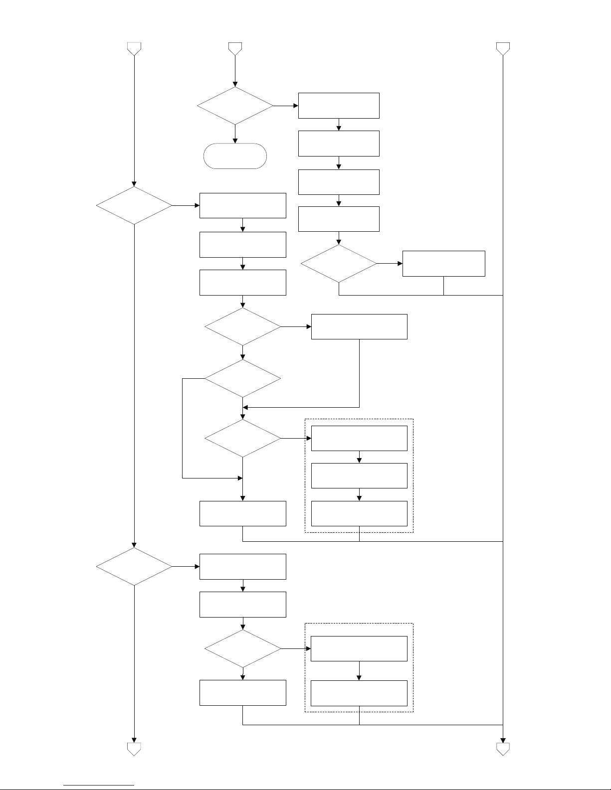
2.5 AI_Transducer Block Configuration Flowchart
Configure 5350
Transducer block
Temperature
measurement?
Set
PRIMARY_VALUE_UNIT
to F,R,C or K
RTD?
Thermo-couple?
Set LIN_TYPE to RTD
type (Pt100 etc.)
4-wire?
Set
SENSOR_CONNECTION
to 2-,3- or 4-wire.
Enter wire resistance in
Ohms for both wires to
COMP_WIRE1
2-wire?
Enter wire resistance in
Ohms for both wires to
COMP_WIRE2
YES
Enter setup for sensor 2:
YES
Set LIN_TYPE to TC
type (TC K etc.)
Set RJ_TYPE (internal,
external etc.)
Set LIN_TYPE_2 to RTD
type (Pt100 etc.)
Set
SENSOR_MEAS_TYPE
to single sensor type
Dual sensor?
Enter setup for sensor 2:
Set LIN_TYPE_2 to TC type
(TC K etc.)
Enter RJ temperature to
EXTERNAL_RJ_VALUE
RJ_TYPE
external?
YES
YES
RJ_TYPE
ext. 2.wire?
Enter wire resistance in
Ohms for both wires to
COMP_WIRE_RJ
YES
YES
YES
2c
Set
SENSOR_MEAS_TYPE
to single sensor type
2b
2a
Set SENSOR_MEAS_TYPE
to dual sensor type
Set SENSOR_MEAS_TYPE
to dual sensor type
YES
Dual sensor? YES
11
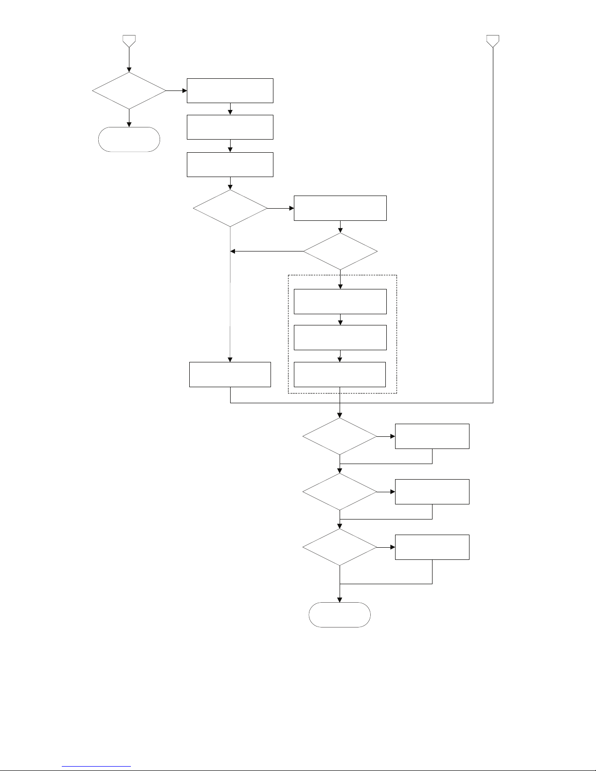
2c
RTD+Thermo-
couple?
2b
Set LIN_TYPE to TC
type (TC K etc.)
Set RJ_TYPE
(internal, external etc.)
Set
SENSOR_MEAS_TYPE
to dual sensor type
Set LIN_TYPE_2 to
RTD type (Pt100 etc.)
Enter RJ temperature to
EXTERNAL_RJ_VALUE
RJ_TYPE
external?
YES
YES
2a
Error! (try again)
Resistance?
Set
PRIMARY_VALUE_UNIT
to Ohm or kOhm
Set
SENSOR_CONNECTION
to 2-,3- or 4-wire.
Dual sensor?
Enter wire resistance in
Ohms for both wires to
COMP_WIRE1
2-wire?
YES
Enter setup for sensor 2:
YES
Set LIN_TYPE_2 to
”no linearisation” or
”linearisation table”
Set
SENSOR_MEAS_TYPE
to single sensor type
Set LIN_TYPE to
”no linearisation” or
”linearisation table”
Set SENSOR_MEAS_TYPE
to dual sensor type
Enter wire resistance in
Ohms for both wires to
COMP_WIRE2
Millivolts?
Set
PRIMARY_VALUE_UNIT
to V,mV or µV
Set LIN_TYPE to
”no linearisation” or
”linearisation table”
Dual sensor?
Set LIN_TYPE_2 to
”no linearisation” or
”linearisation table”
Set
SENSOR_MEAS_TYPE
to single sensor type
Set SENSOR_MEAS_TYPE
to dual sensor type
3b
3a
Enter setup for sensor 2:
YES
YES
YES
4-wire?
YES
12
3b3a
Potentiometer?
Set
PRIMARY_VALUE_UNIT
to ”%”
Set
SENSOR_CONNECTION
to 3- or 4-wire.
Enter wire resistance in
Ohms for 2 wires to
COMP_WIRE1
3-wire?
YES
Enter setup
for sensor 2:
YES
Set LIN_TYPE_2 to
”no linearisation” or
”linearisation table”
Set
SENSOR_MEAS_TYPE
to single sensor type
Set LIN_TYPE to
”no linearisation” or
”linearisation table”
Set SENSOR_MEAS_TYPE
to dual sensor type
Enter wire resistance in
Ohms for 2 wires to
COMP_WIRE2
Error! (try again)
Finished.
Transducer block
is configured!
Enter Custom RTD
polynomial values
Linearisation
table?
Custom RTD?
Enter linearisation
table values
YES
YES
Enter Custom TC
polynomial values
Custom TC? YES
Dual sensor?
YES
13
2.6 - Transducer Block Examples Setup
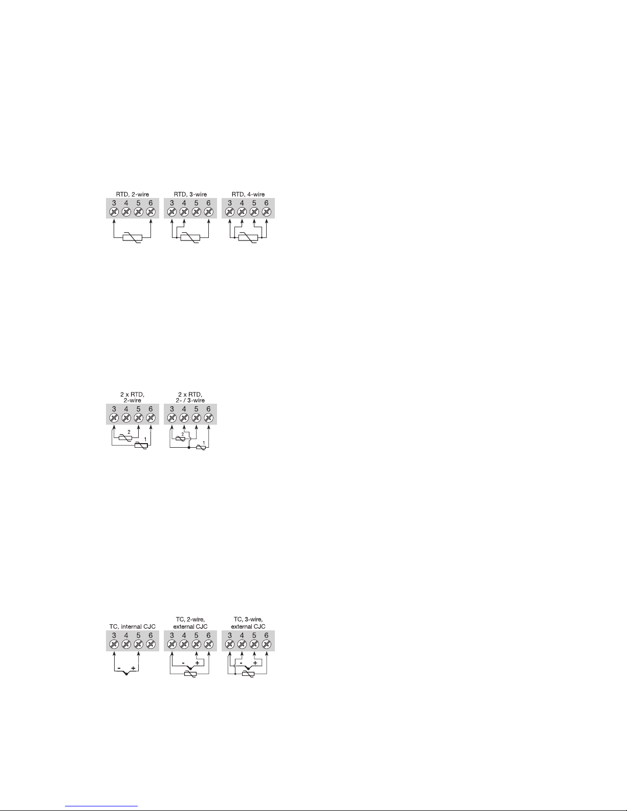
2.6.1 Measurement of RTD with one sensor:
PRIMARY_VALUE_UNIT .......= K, °C, °F or °R
LIN_TYPE....................= Any RTD
LIN_TYPE_2 .................= N/A (ignored in setup check)
SENSOR_MEAS_TYPE.........= PV = SV_1, SV_2 not available
SENSOR_CONNECTION .......= 2-, 3- or 4-wire
SENSOR_CONNECTION_2 .....= N/A (ignored in setup check)
RJ_TYPE .....................= N/A (ignored in setup check)
Connections:
2.6.2 Measurement of RTD with two sensors:
PRIMARY_VALUE_UNIT .......= K, °C, °F or °R
LIN_TYPE....................= Any RTD
LIN_TYPE_2 .................= Any RTD
SENSOR_MEAS_TYPE.........= Anything, but not "PV = SV_1, SV_2 not available"
SENSOR_CONNECTION .......= 2- or 3-wire
SENSOR_CONNECTION_2 .....= Default set to 2-wire
RJ_TYPE .....................= N/A (ignored in setup check)
Connections:
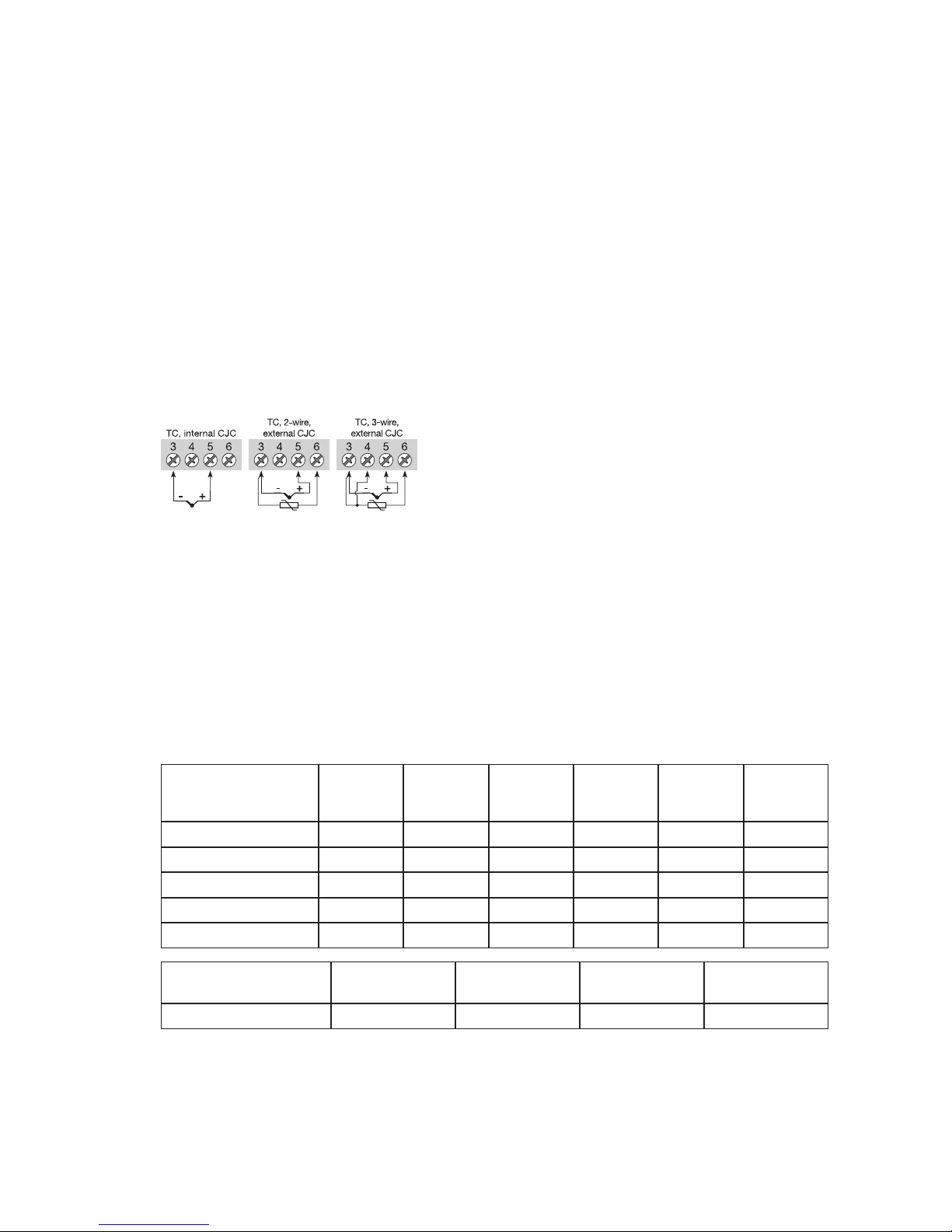
2.6.3 Measurement of thermocouple with one sensor:
PRIMARY_VALUE_UNIT .......= K, °C, °F or °R
LIN_TYPE....................= Any TC
LIN_TYPE_2 .................= N/A (ignored in setup check)
SENSOR_MEAS_TYPE.........= PV = SV_1, SV_2 not available
SENSOR_CONNECTION .......= N/A (ignored in setup check)
SENSOR_CONNECTION_2 .....= N/A (ignored in setup check)
RJ_TYPE .....................= No Reference Junction, Internal, External (constant value),
Sensor 2-wire or Sensor 3-wire
Connections:
Connections with two sensors
can be configured for
2 measurements, dierence,
average or redundancy
14
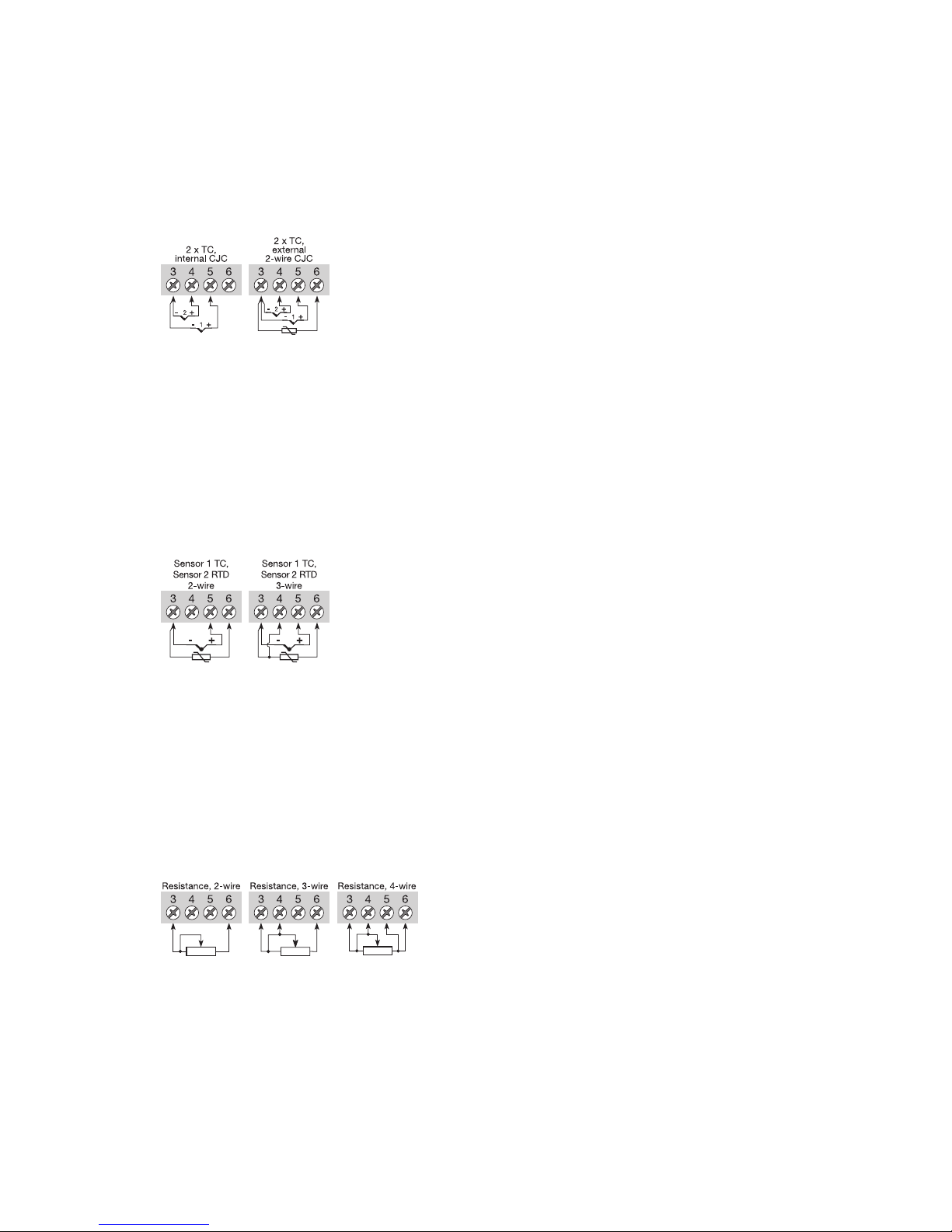
2.6.4 Measurement of thermocouple with two sensors:
PRIMARY_VALUE_UNIT .......= K, °C, °F or °R
LIN_TYPE....................= Any TC
LIN_TYPE_2 .................= Any TC
SENSOR_MEAS_TYPE.........= Anything, but not "PV = SV_1, SV_2 not available"
SENSOR_CONNECTION .......= N/A (ignored in setup check)
SENSOR_CONNECTION_2 .....= N/A (ignored in setup check)
RJ_TYPE .....................= No RJ, Internal, External (constant value) or Sensor 2-wire
Connections:
2.6.5 Measurement of combined sensors (Sensor 1 = TC and Sensor 2 = RTD):
PRIMARY_VALUE_UNIT .......= K, °C, °F or °R
LIN_TYPE....................= Any TC
LIN_TYPE_2 .................= Any RTD
SENSOR_MEAS_TYPE.........= Anything, but not "PV = SV_1, SV_2 not available"
SENSOR_CONNECTION .......= N/A (ignored in setup check)
SENSOR_CONNECTION_2 .....= 2- or 3-wire
RJ_TYPE ....................= No Reference Junction, Internal, External (constant value)
Connections:
2.6.6 Measurement of resistance (linear) with one sensor:
PRIMARY_VALUE_UNIT .......= Ohm or kOhm
LIN_TYPE....................= No linearisation
LIN_TYPE_2 .................= N/A (ignored in setup check)
SENSOR_MEAS_TYPE.........= PV = SV_1, SV_2 not available
SENSOR_CONNECTION .......= 2-, 3- or 4-wire
SENSOR_CONNECTION_2 .....= N/A (ignored in setup check)
RJ_TYPE .....................= N/A (ignored in setup check)
Connections:
Connections with two sensors
can be configured for
2 measurements, dierence,
average or redundancy
Connections with two sensors
can be configured for
2 measurements, dierence,
average or redundancy
15
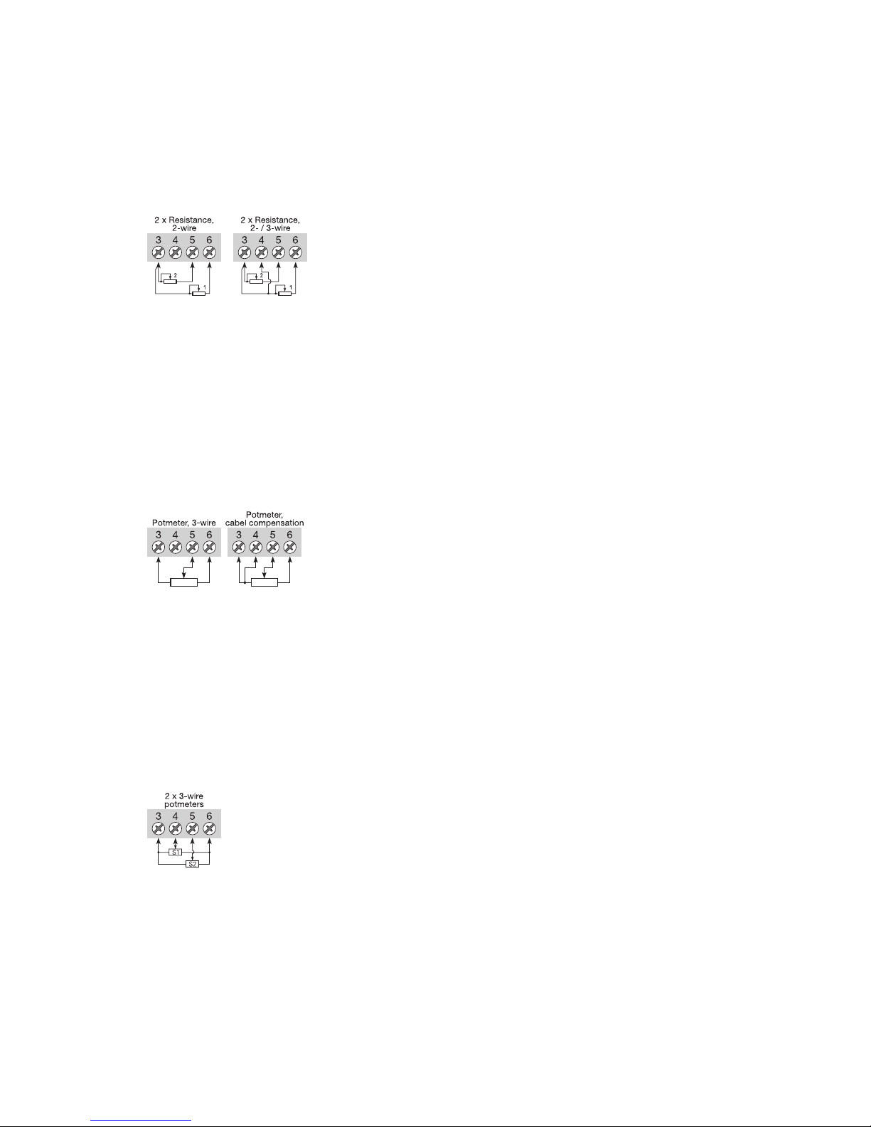
2.6.7 Measurement of resistance (linear) with two sensors:
PRIMARY_VALUE_UNIT .......= Ohm or kOhm
LIN_TYPE....................= No linearisation
LIN_TYPE_2 .................= No linearisation
SENSOR_MEAS_TYPE.........= Anything, but not "PV = SV_1, SV_2 not available"
SENSOR_CONNECTION .......= 2- or 3-wire
SENSOR_CONNECTION_2 .....= Default set to 2-wire
RJ_TYPE .....................= N/A (ignored in setup check)
Connections:
2.6.8 Measurement of potentiometer (linear) with one sensor:
PRIMARY_VALUE_UNIT .......= %
LIN_TYPE....................= No linearisation
LIN_TYPE_2 .................= N/A (ignored in setup check)
SENSOR_MEAS_TYPE.........= PV = SV_1, SV_2 not available
SENSOR_CONNECTION .......= 3- or 4-wire
SENSOR_CONNECTION_2 .....= N/A (ignored in setup check)
RJ_TYPE .....................= N/A (ignored in setup check)
Connections:
2.6.9 Measurement of potentiometer (linear) with two sensors:
PRIMARY_VALUE_UNIT .......= %
LIN_TYPE....................= No linearisation
LIN_TYPE_2 .................= No linearisation
SENSOR_MEAS_TYPE.........= Anything, but not "PV = SV_1, SV_2 not available"
SENSOR_CONNECTION .......= Default set to 3-wire
SENSOR_CONNECTION_2 .....= Default set to 3-wire
RJ_TYPE .....................= N/A (ignored in setup check)
Connections:
Connections with two sensors
can be configured for
2 measurements, dierence,
average or redundancy
Connections with two sensors
can be configured for
2 measurements, dierence,
average or redundancy

16
2.6.10 Measurement of voltage (linear) with one sensor:
PRIMARY_VALUE_UNIT .......= µV, mV or V
LIN_TYPE....................= No linearisation
LIN_TYPE_2 .................= N/A (ignored in setup check)
SENSOR_MEAS_TYPE.........= PV = SV_1, SV_2 not available
SENSOR_CONNECTION .......= N/A (ignored in setup check)
SENSOR_CONNECTION_2 .....= N/A (ignored in setup check)
RJ_TYPE .....................= N/A (ignored in setup check)
Connections:
2.6.11 Measurement of voltage (linear) with two sensors:
PRIMARY_VALUE_UNIT .......= µV, mV or V
LIN_TYPE....................= No linearisation
LIN_TYPE_2 .................= No linearisation
SENSOR_MEAS_TYPE.........= Anything, but not "PV = SV_1, SV_2 not available"
SENSOR_CONNECTION .......= N/A (ignored in setup check)
SENSOR_CONNECTION_2 .....= N/A (ignored in setup check)
RJ_TYPE .....................= N/A (ignored in setup check)
Connections:
2.6.12 Measurement of 2 potentiometers (with Linear interpolation linearisation):
PRIMARY_VALUE_UNIT ....... = %
LIN_TYPE.................... = Table Linearisation
LIN_TYPE_2 ................. = Table Linearisation (same table as sensor 1)
SENSOR_MEAS_TYPE......... = Anything, but not "PV = SV_1, SV_2 not available"
SENSOR_CONNECTION ....... = Default set to 3-wire
SENSOR_CONNECTION_2 ..... = Default set to 3-wire
RJ_TYPE ..................... = N/A (ignored in setup check)
Connections:
The coordinates (x,y) describing the linear interpolation linearisation must be entered in PR_
CUST_LIN Block (PA Slot 4). See 2.9.2 Linear Interpolation Linearisation, Paramter List for
further details.
Example:
The coordinates for converting the signal from a logarithmic potentiometer to a linear signal.
TAB_ACTUAL_NUMBER = 10 (number of linearisation points to follow up to max 50)
TAB_XY_VALUE1 = 0,0; -100
TAB_XY_VALUE2 = 0,1; 0
TAB_XY_VALUE3 = 0,2; 100
TAB_XY_VALUE4 = 0,4; 200
Connections with two sensors
can be configured for
2 measurements, dierence,
average or redundancy
Connections with two sensors
can be configured for
2 measurements, dierence,
average or redundancy
17
TAB_XY_VALUE5 = 0,8; 300
TAB_XY_VALUE6 = 1,6; 400
TAB_XY_VALUE7 = 3,2; 500
TAB_XY_VALUE8 = 6,4; 600
TAB_XY_VALUE9 = 12,8; 700
TAB_XY_VALUE10 = 25,6; 800
(Output will readout 325% with 1,0% potentiometer value)
2.6.13 Measurement of TC (with Custom Polynomial Linearisation) on sensor 1
PRIMARY_VALUE_UNIT = K, °C, °F or °R
LIN_TYPE = Custom defined TC
LIN_TYPE_2 = N/A (ignored in setup check)
SENSOR_MEAS_TYPE = PV = SV_1, SV_2 not available
SENSOR_CONNECTION = N/A (ignored in setup check)
SENSOR_CONNECTION_2 = N/A (ignored in setup check)
RJ_TYPE = No Reference Junction, Internal, External (constant value) or
Sensor 2-wire or Sensor 3-wire
Connections:
Now enter the Custom TC parameters in PR_CUST_LIN Block (PA Slot 4). See 2.9.4 Custom Pol-
ynomial Linearisation, Parameter List for further details.
Remember to enter values for the RJ polynomial if RJ_TYPE is any value other than “No refer-
ence Junction”.
Example:
The parameters and coecients for converting a special TC to a linear temperature signal.
CUSTOM_TC_NAME = Custom TC Example
CUSTOM_TC_POLY_COUNT = 5
CUSTOM_TC_MIN_IN = -6500.0
CUSTOM_TC_MIN_OUT = -100.0
CUSTOM_TC_MAX_OUT = 1200.0
A TC input of 5000 µV and an RJ temperature of 25ºC will make POLY_3 the active and the out-
put will be:
URJ = -3.94 *10-1 + 3.94 * 101* 25 + 2.65 * 10-2 * 252- 1.11 * 10-4 * 253= 1000 µV
This voltage is to be added to the TC voltage (5000 + 1000), and the resulting temperature will be:
4.18 + 2.26
*10-2 *6000 +1.41*10-7 *60002+ 1.50 *10-11 *60003- 1.35 *10-15 *60004=
146.3 °C
See 2.9.3 Custom polynomial linearisation, Description for formula and further details.
CUSTOM_TC_POLY_X
max. input
limit in μV
for POLY_X
4th degree
coefficient
for POLY_X
3th degree
coefficient
for POLY_X
2th degree
coefficient
for POLY_X
1st degree
coefficient
for POLY_X
0 degree
coefficient
for POLY_X
CUSTOM_TC_POLY_1 -3200.0 -3.84E-13 -5.65E-9 -3.36E-5 -6.10E-2 -8.44E1
CUSTOM_TC_POLY_2 3500.0 -8.13E-15 7.29E-11 -4.18E-7 2.53E-2 -1.08E-2
CUSTOM_TC_POLY_3 10000.0 -1.35E-15 1.50E-11 1.41E-7 2.26E-2 4.18
CUSTOM_TC_POLY_4 30000.0 3.49E-18 2.19E-12 -1.53E-7 2.68E-2 -9.26
CUSTOM_TC_POLY_5 70000.0 6.27E-17 -8.76E-12 5.34E-7 8.69E-3 1.65E2
3th degree
coefficient
2th degree
coefficient
1st degree
coefficient
0 degree
coefficient
CUSTOM_TC_RJ_POLY -1.11E-4 2.65E-2 3.94E1 3.94E-1
18
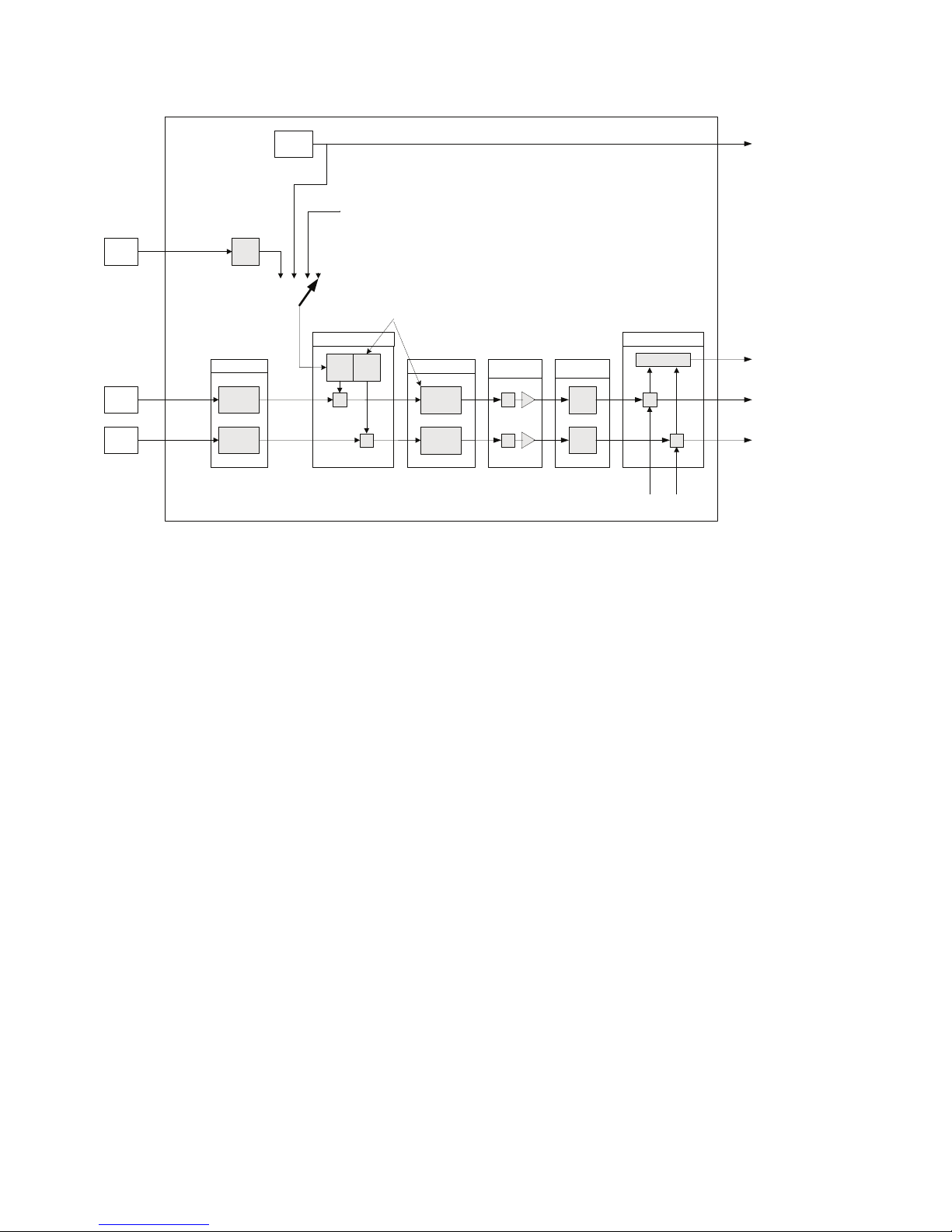
RJ
temp.
Intern
temp. INTERN_TEMP
EXTERNAL_RJ_VALUE
LIN
R.J. Comp.
RJ_TYPE
Input
INPUT1
INPUT2
T1
T2
Linearisation
+
+ LIN
LIN
RJ_TEMP
(none)
Arithmetic
+
+
+,-, redund.
SECONDARY_VALUE_1
SECONDARY_VALUE_2
PRIMARY_VALUE
SENSOR_MEAS_TYPE
BIAS_1 BIAS_2
LIN
LIN_TYPE_1/2
SENSOR_CONNECTION_1/2
COMP_WIRE_1/2
Process
calibration
+
+
Min/Max hold
min/
max
min/
max
MIN_SENSOR_VALUE_1/2
MAX_SENSOR_VALUE_1/2
RTDX_FACTOR_1/2
CAL_POINT_HI_1/2
CAL_ACTUAL_HI_1/2
CABLE_RES1/2
RJ
RJ_COMP_WIRE
SENSOR_WIRE_CHECK_1/2
SENSOR_WIRE_CHECK_RJ
CUSTOM_TC_..
TAB_X_Y_VALUE
CUSTOM_RTD_..
(Channel_4)
(Channel_1)
(Channel_2)
(Channel_3)
AI_TRANSDUCER and PR_CUST_LIN schematic
CAL_POINT_LO_1/2
CAL_ACTUAL_LO_1/2
2.7 AI_Transducer and PR_CUST_LIN Block, Schematic

19
2.8 AI_TRANSDUCER Block Parameter List
2.8.1 Sensor characterising parameters
Parameter
Rel.
Index
FF
Description Type Store Size
byte
RO /
R/W Min. Max. Default
PRIMARY_VALUE_UNIT 14
Selects the unit code of the PRIMARY_VALUE and other
values.
1000 = K (Kelvin)
1001 = °C (degree Celsius)
1002 = °F (degree Fahrenheit)
1003 = Rk (Rankine)
1240 = V (volt)
1243 = mV millivolt
1244 = µV microvolt
1281 = Ohm Ohm
1284 = kOhm kiloOhm
1342 = % (percent)
Un-
signed
16
SRC 2 R/W 1001
(°C)
LIN_TYPE 18
Select the type of sensor 1:
0 = no linearisation
1 = linearisation table
100 = RTD Pt10 a = 0.003850 (IEC 60751)
101 = RTD Pt50 a = 0.003850 (IEC 60751)
102 = RTD Pt100 a = 0.003850 (IEC 60751))
103 = RTD Pt200 a = 0.003850 (IEC 60751))
104 = RTD Pt500 a = 0.003850 (IEC 60751))
105 = RTD Pt1000 a = 0.003850 (IEC 60751)
106 = RTD Pt10 a = 0.003916 (JIS C1604-81)
107 = RTD Pt50 a = 0.003916 (JIS C1604-81)
108 = RTD Pt100 a = 0.003916 (JIS C1604-81)
122 = RTD Ni50 a = 0.006180 (DIN 43760)
123 = RTD Ni100 a = 0.006180 (DIN 43760)
124 = RTD Ni120 a = 0.006180 (DIN 43760)
125 = RTD Ni1000 a = 0.006180 (DIN 43760)
126 = RTD Cu10 a = 0.004270
127 = RTD Cu100 a = 0.004270
128 = TC Type B, Pt30Rh-Pt6Rh (IEC 584)
129 = TC Type C (W5), W5-W26Rh (ASTM E 988)
130 = TC Type D (W3), W3-W25Rh (ASTM E 988)
131 = TC Type E, Ni10Cr-Cu45Ni (IEC 584)
133 = TC Type J, Fe-Cu45Ni (IEC 584)
134 = TC Type K, Ni10Cr-Ni5 (IEC 584)
135 = TC Type N, Ni14CrSi-NiSi (IEC 584)
136 = TC Type R, Pt13Rh-Pt (IEC 584)
137 = TC Type S, Pt10Rh-Pt (IEC 584)
138 = TC Type T, Cu-Cu45Ni (IEC 584)
139 = TC Type L, Fe-CuNi (DIN 43710)
140 = TC Type U, Cu-CuNi (DIN 43710)
240 = Custom-defined TC
241 = Custom-defined RTD
242 = Custom-defined RTD PtX a=0.003850 (X factor of Pt1)
243 = Custom-defined RTD NiX a=0.006180 (X factor of Ni1)
244 = Custom-defined RTD CuX a=0.004270 (X factor of Cu1)
245 = Custom-defined RTD PtX a=0.003916 (X factor of Pt1)
Un-
signed
8
SRC 1 R/W 102
(Pt100)
UPPER_SENSOR_LIMIT 21
Physical upper limit function of sensor1 (e.g. Pt 100 =
850°C) and input range.
The unit of UPPER_SENSOR_LIMIT is the PRIMARY_
VALUE_UNIT.
Float N 4 RO 850
LOWER_SENSOR_LIMIT 22
Physical lower limit function of sensor1 (e.g. Pt 100 =
-200°C) and input range.
The unit of LOWER_SENSOR_LIMIT is the PRIMARY_
VALUE_UNIT.
Float N 4 RO -200
LOWER_SENSOR_LIMIT_2 39
Physical lower limit function of sensor2 (e.g. Pt 100 =
-200°C) and input range.
The unit of LOWER_SENSOR_LIMIT is the PRIMARY_
VALUE_UNIT.
Float N 4 RO -200
UPPER_SENSOR_LIMIT_2 40
Physical upper limit function of sensor2 (e.g. Pt 100 =
+850°C) and input range.
The unit of UPPER_SENSOR_LIMIT is the PRIMARY_
VALUE_UNIT.
Float N 4 RO 850
LIN_TYPE_2 41 Select the type of sensor 2:
See LIN_TYPE for selection and supported types
Un-
signed
8
SRC 1 R/W 102

20
AI_TRANSDUCER Block Parameter List
2.8.2 RTD / Resistor specific parameters
Parameter
Rel.
Index
FF
Description Type Store Size
byte
RO /
R/W Min. Max. Default
SENSOR_CONNECTION 35
Connection to sensor 1, select for 2-, 3- and 4-wire con-
nection. Ignored if sensor 1 is not a resistive sensor.
Defined codes:
0 = 2 wires
1 = 3 wires
2 = 4 wires
Un-
signed
8
SRC 1 R/W 1
COMP_WIRE1 36 Value in OHM to compensate line resistance when
Sensor 1 is a resistive sensor, connected with 2 wires. Float SRC 4 R/W 0 100 0
COMP_WIRE2 37 Value in OHM to compensate line resistance when
Sensor 2 is a resistive sensor, connected with 2 wires. Float SRC 4 R/W 0 100 0
SENSOR_CONNECTION_2 38
Connection to sensor 2, select for 2-, 3- and 4-wire con-
nection. Ignored if sensor 2 is not a resistive sensor.
Defined codes:
0 = 2 wires
1 = 3 wires
Un-
signed
8
SRC 1 R/W 0
CABLE_RES1 63
For 3- or 4-wire resistance measurements.
Indicates the measured cable resistance in the wire
connected to terminal 3. For 3-wire measurements it is
multiplied by 2
Float D 4 RO 0,0
CABLE_RES2 64
For 4-wire resistance measurements.
Indicates the measured cable resistance in the wire con-
nected to terminal 6.
Float D 4 RO 0,0
RTDX_FACTOR_1 65 Indicates the X factor for custom defined PtX, NiX, CuX
for LIN_TYPE
Un-
signed
16
SRC 2 R/W 100
RTDX_FACTOR_2 66 Indicates the X factor for custom defined PtX, NiX, CuX
for LIN_TYPE_2
Un-
signed
16
SRC 2 R/W 100
2.8.3 Thermocouple specific parameters
Parameter
Rel.
Index
FF
Description Type Store Size
byte
RO /
R/W Min. Max. Default
RJ_TEMP 32
Reference junction temperature. The unit of RJ_TEMP is
the PRIMARY_VALUE_UNIT. If PRIMARY_VALUE_UNIT is
no temperature unit (e.g. mV) RJ_TEMP is stated in °C.
Float D 4 RO 0
RJ_TYPE 33
Select reference junction from internal to fixed value.
Ignored for sensors which are not thermocouple types.
Defined codes:
0 = No reference: Compensation is not used (e.g. for
TC type B).
1 = Internal: Reference junction temperature is
measured by the device itself, via
an internally mounted sensor.
2 = External: The fixed value EXTERNAL_RJ_
VALUE is used for compensation.
The reference junction must be kept
at a constant temperature (e.g. by a
reference junction thermostat).
3 = Sensor, 2-w.: Reference junction temperature is
measured by external 2-wire con-
nected Pt100 sensor.
4 = Sensor, 3-w: Reference junction temperature is
measured by external 3-wire con-
nected Pt100 sensor.
Un-
signed
8
SRC 1 R/W 0
EXTERNAL_RJ_VALUE 34
Fixed temperature value of an external reference junc-
tion. The unit of EXTERNAL_RJ_VALUE is the PRIMARY_
VALUE_UNIT. If PRIMARY_VALUE_UNIT is no temperature
unit (e.g. mV) EXTERNAL_RJ_VALUE is stated in °C.
Float SRC 4 R/W -40
(°C)
135
(°C) 0
RJ_COMP_WIRE 42 Value in OHM to compensate line resistance when
External RJ sensor, connected with 2 wires is used. Float SRC 4 R/W 0 100 0
Table of contents
Other PR Transmitter manuals


