Draminski iScan 2 MULTI User manual

DRAMIŃSKI
iScan 2multi
Veterinary Ultrasound Scanner
www.draminski.com ISO 9001
1.0_16112020_xxxxx
USER GUIDE

DRAMIŃSKI iScan 2multi - User Guide
2
Manufactured by:
DRAMIŃSKI S.A.
Owocowa 17
10-860 Olsztyn
Poland
Phone No: +48 89 527 11 30
www.draminski.com
facebook.com/
com.draminski
instagram.com/
draminski_ultrasound_scanners/
linkedin.com/
company/draminski-sa/
Dramiński S.A. has implemented and maintains comprehensive quality management
system in accordance with the EN ISO 9001 requirements. The system is periodically
audited by TUV Rheinland LGA Products GmbH notied body, Tillystrasse 2,
90431, Nurnberg, Germany which participates in the conformity assessment process.
Declaration of conformity
It can be obtained from our Sales Department:
Phone No:
Phone No: +48 89 527 11 30
e-mail:export@draminski.com
We wish you and the users of the product a lot of success in taking care of your patients.
We are sure that with our product you will be able to provide good care for your patients.
DRAMIŃSKI will be glad to receive your feedback regarding the device and this manual.
Please call us at: +48 89 527 11 30
Prepared by DRAMINSKI S.A.
All rights reserved.
Copying without DRAMINSKI S.A. approval is forbidden.

3
DRAMIŃSKI iScan 2multi - User Guide
Introduction
1. Introduction ............................................................................................5
1.1. Information about the user guide of the device ......................................................5
1.2. Warnings, comments and symbols used in the user guide ............................................5
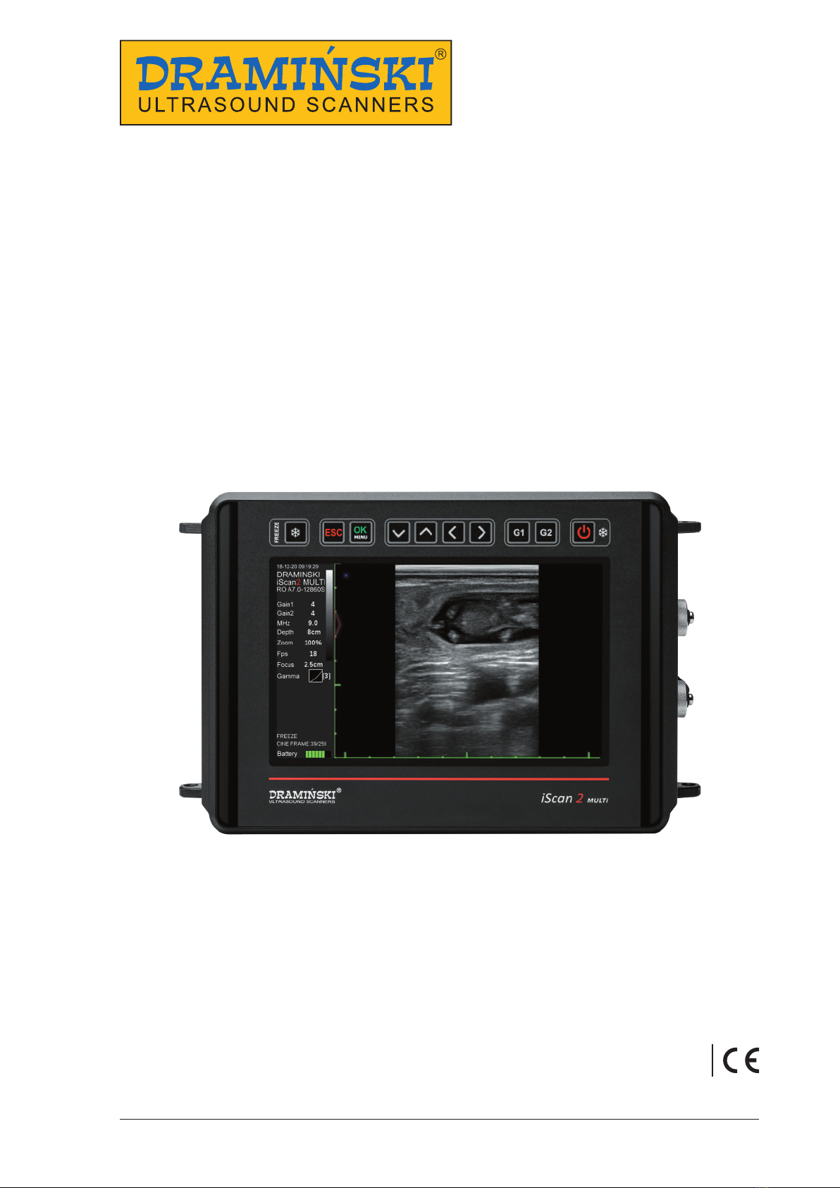
1.3. Preliminary information about iScan 2 MULTI – a portable ultrasound scanner ........................5
2. Safe use.................................................................................................6
3. List of components of DRAMIŃSKI iScan 2 MULTI ultrasound scanner......................................7
4. Design of the iScan 2 MULTI ultrasound scanner..........................................................8
4.1. Casing..............................................................................................8
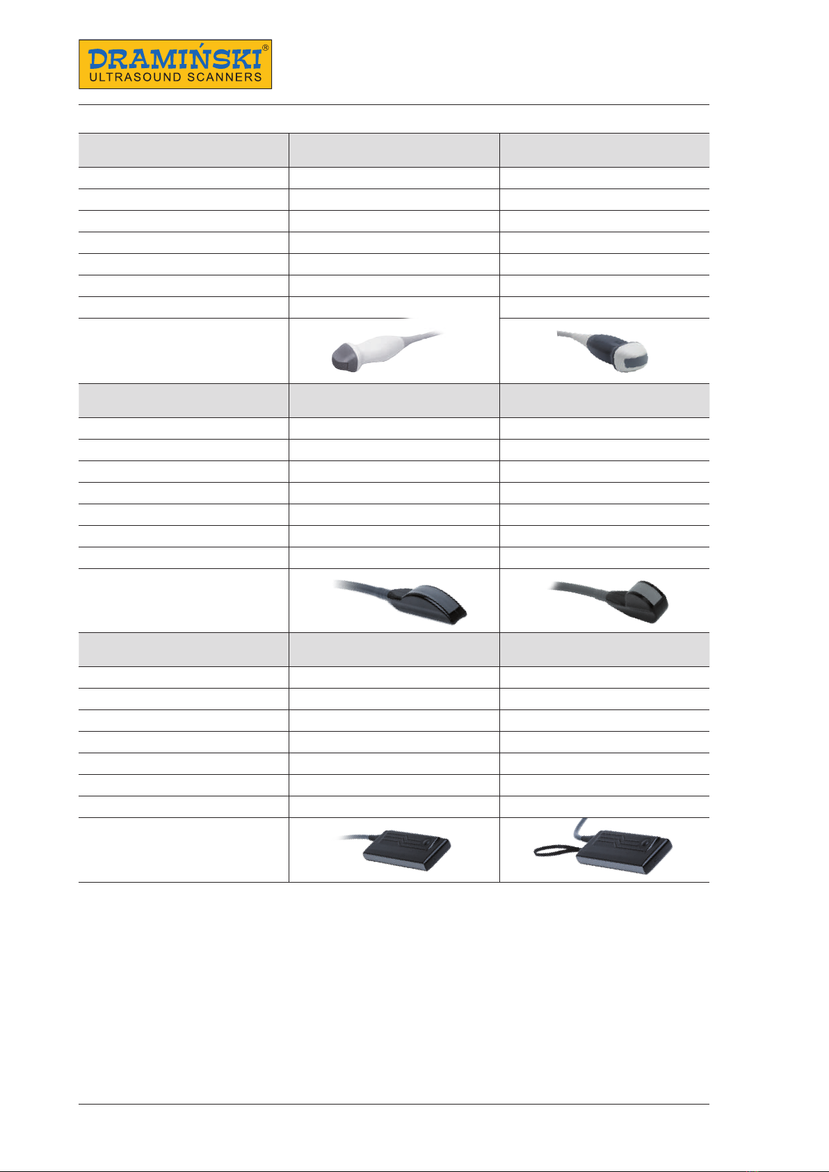
4.2. Probe...............................................................................................9
4.3. Battery ...........................................................................................11
4.4. Charger ..........................................................................................12
5. Getting started........................................................................................13
5.1. How to charge the batteries.......................................................................13
5.2. How to connect the batteries to the ultrasound scanner ...........................................13
5.3. Connecting and disconnecting a probe............................................................14
5.4. Attaching the suspenders .........................................................................14
5.5. How to turn the ultrasound scanner on............................................................ 14
6. How to end operation of the ultrasound scanner . . . . . . . . . . . . . . . . . . . . . . . . . . . . . . . . . . . . . . . . . . . . . . . . . . . . . . . 15
6.1. How to turn the ultrasound scanner o............................................................15
6.2. Cleaning and disinfection .........................................................................15
7. User control panel..................................................................................... 16
8. Menu structure of the ultrasound scanner..............................................................17
8.1. Personalization of the Quick Access Menu (Q)......................................................19
9. Description of the ultrasound scanner's functions ......................................................20
9.1. Setting the parameters of imaging ................................................................20
9.1.1. Gain adjustment .............................................................................20
9.1.2. Adjustment of scanning depth................................................................ 20
9.1.3. Focusing . . . . . . . . . . . . . . . . . . . . . . . . . . . . . . . . . . . . . . . . . . . . . . . . . . . . . . . . . . . . . . . . . . . . . . . . . . . . . . . . . . . . . 20
9.1.4. Frequency ................................................................................... 20
9.1.5. Gamma ......................................................................................21
9.1.6. Frame averaging .............................................................................21
9.1.7. Zoom ........................................................................................21
9.1.8. LuciD ........................................................................................22
9.1.9. Negative .....................................................................................22
9.2. Presets ........................................................................................... 22
9.2.1. Creating presets.............................................................................. 22
9.2.2. Loading presets .............................................................................. 23
9.3. How to freeze the image ..........................................................................23
9.4. Cine-loops........................................................................................ 23
9.5. Measurements.................................................................................... 23
9.5.1. Distance .....................................................................................23
9.5.2. Surface area.................................................................................. 24
9.5.3. Volume ......................................................................................24
9.5.4. Backfat thickness measurement...............................................................24
9.5.5. Embryo biometry.............................................................................24
9.5.5.1. Cow CRL – embryo length................................................................ 25
9.5.5.2. Cow BPD – head diameter measured between the fontanelles.............................25
9.5.5.3. Horse VD – germinal vesicle size ..........................................................25
9.5.5.4. Horse HD – head diameter ............................................................... 25
9.5.5.5. Horse OD – eye diameter................................................................. 26
9.5.5.6. Sheep CRL – embryo length ..............................................................26
9.5.5.7. Lama BPD – head diameter measured between the fontanelles. ...........................26

DRAMIŃSKI iScan 2multi - User Guide
4
9.5.5.8. Sow CRL – embryo length ................................................................26
9.5.6. Grid.......................................................................................... 26
9.6. Full screen ........................................................................................26
9.7. Rotating images .................................................................................. 27
9.8. How to save data .................................................................................27
9.8.1. Saving images................................................................................ 27
9.8.2. Saving cine loops.............................................................................28
9.9. How to load the data onto the screen.............................................................. 28
9.9.1. Uploading images............................................................................ 28
9.9.2. Uploading cine-loops.........................................................................28
9.9.3. Browsing images and cine loops ..............................................................28
9.10. How to export data to the external data storage device ........................................... 29
9.11. How to delete data from the internal memory ....................................................29
10. Imaging modes . . . . . . . . . . . . . . . . . . . . . . . . . . . . . . . . . . . . . . . . . . . . . . . . . . . . . . . . . . . . . . . . . . . . . . . . . . . . . . . . . . . . . . 30
10.1. B Mode..........................................................................................30
10.2. B+B Mode .......................................................................................30
10.3. B+M Mode ...................................................................................... 31
11. System settings . . . . . . . . . . . . . . . . . . . . . . . . . . . . . . . . . . . . . . . . . . . . . . . . . . . . . . . . . . . . . . . . . . . . . . . . . . . . . . . . . . . . . . 32
11.1. Change left / right ............................................................................... 32
11.2. Date/Time.......................................................................................32
11.3. Brightness....................................................................................... 32
11.4. Language .......................................................................................32
11.5. Factory settings .................................................................................32
11.6. Automatic shutdown ............................................................................32
12. Accessories .......................................................................................... 33
12.1. Goggles .........................................................................................33
12.2. Screen sun shield ................................................................................34
12.3. Linear rectal probe extension for cattle. .......................................................... 35
12.4 Linear rectal probe extension for sheep. ..........................................................35
12.5 Battery support...................................................................................35
13. Maintenance of the device and the probes............................................................36
13.1. Cleaning and disinfection........................................................................36
13.2. Technical inspections ............................................................................37
14. Transportation of the device..........................................................................38
15. Operational and technical notes......................................................................39
15.1. Troubleshooting................................................................................. 39
16. iScan 2 MULTI technical specication .................................................................41
17. Warranty............................................................................................. 42

5
DRAMIŃSKI iScan 2multi - User Guide
1. Introduction
1.1. Information about the user guide of the device
The individual sections of the user guide describe design, accessories of the device, preparing it to operation,
functions and use of the ultrasound scanner. Before starting to use the ultrasound scanner, please read carefully
the user guide.
Reading the content of the user guide does not substitute even basic ultrasonography
training. We recommend the user to take an authorized ultrasound training.
1.2. Warnings, comments and symbols used in the user guide
This user guide uses the following distinguishing signs to emphasise important information:
Warning! Pay particular attention to safety of the patient or of the device user.
Attention! - Pay attention to the safety of the device or its proper operation.
Bold text - To draw attention to important fragments in the user guide or to make the information clearer and
more legible.
Descriptions of diagrams and gures to make details more visible.
The symbols used in the user guide do not provide complete information about safety instructions. Therefore,
the safety instructions (section 2) must be read rst and followed!
Symbols used in the text:
<x.x.x> – reference to section x.x.x
(option) – availability of the feature depends on the version of the device or its equipment
1.3. Preliminary information about iScan 2 MULTI – a portable ultrasound scanner
The iScan 2 MULTI ultrasound scanner is intended for diagnostics of animals, in particular of livestock. It can
be used for examination of reproductive system, lungs, parts of digestive system, and others, as well as for
determination of breeding value.
The ultrasound scanner can work with various linear and convex probes, e.g. backfat probe and OPU system.

DRAMIŃSKI iScan 2multi - User Guide
6
2. Safe use
Warning! User and patient safety depends on the compliance with the following
guidelines!
1. DRAMIŃSKI iScan 2 MULTI is a device that should be used only by qualied personnel for diagnostic
purposes.
2. The ultrasound scanner and its equipment should be disinfected after their potential contact with conta-
gious substances.
3. The ultrasound scanner cannot be used simultaneously with other high frequency devices (HF).
4. The users of the ultrasound scanner are recommended to have regular technical inspections performed
by the manufacturer every two years.
5. It is forbidden to dismantle the device and perform repairs and adjustments on one’s own, except the
activities described in the user guide.
6. The users of the ultrasound scanner are recommended to regularly check the probe cable and the point
where it is connected to the ultrasound scanner against mechanical damage.
7. If mechanical damage of the probe or the cable is identied, the device needs to be sent to the service
center.
8. The ultrasound scanner has a sturdy design, however, in order to avoid mechanical damage, please, follow
the instructions specied in this section of the user guide.
9. Avoid exposure of the device to strong sunlight. It is recommended to observe the temperature specied
on the labels of the device and its components.
10. The user is forbidden to introduce any modications to the device.
11. DRAMIŃSKI iScan 2 MULTI is an electric device that can be the source of electromagnetic radiation. Its
operation can be disturbed by other electric devices, that is why it is recommended to limit the number of
electric devices in its vicinity as much as possible.
12. When the device and its accessories reach their lifetime, due to the risk for the environment, they should
be recycled by specially qualied entities in accordance with the applicable legislation or returned to the
manufacturer.

7
DRAMIŃSKI iScan 2multi - User Guide
3. List of components of DRAMIŃSKI iScan 2 MULTI ultrasound scanner
Item Name and description Quantity
Standard equipment
1 Ultrasound scanner 1
2 Ultrasound probe 1
3 External battery 1
4 Battery charger with a 230 V charging cable 1
5 USB storage adapter 1
6 Suspenders 1
7 Transport case 1
8 User guide on a USB drive 1
Additional equipment*
9 Goggles option
10 WiFi antenna option
11 Screen sun shield option
12 Linear rectal probe extension for cattle option
13 Linear rectal probe extension for sheep option
14 Battery stand option
15 Stand-o option
16 OPU holder option
*Ask your sales representative about availability.
Any additional accessories for use with the iScan 2 MULTI ultrasound scanner are available upon agreement
with the vendor.

DRAMIŃSKI iScan 2multi - User Guide
8
4. Design of the iScan 2 MULTI ultrasound scanner
Attention!
The ultrasound scanner has a sturdy design. However, during operation and transportation, caution is
necessary in order not to subject the device to strong impacts to avoid damaging it. The sockets should
be protected against dirt and moisture.
4.1. Casing
The view and description of the elements of the casing:
Hooks for carrying straps
Screen
Keyboard
Goggles connection socket
Data transfer socket
Casing. Front view.
13
4
5
1
1
2
3
4
5
11
2
Freeze
Exit
Conrm / Menu
Navigation buttons
General / overall gain
Far eld gain
ON / OFF / Freeze
Keyboard
1 2 3 4 5 6 7
1
2
3
4
5
6
7
Battery
Battery attachment system
Latch
Probe socket protection slide
Probe socket lock
2 2
3
1
2
3
14
4
Casing. Rear view.
5
5

9
DRAMIŃSKI iScan 2multi - User Guide
4.2. Probe
The iScan 2 MULTI ultrasound scanner can work with various probes. The compatible probes are listed below.
Software update can increase the number of compatible probes. Ask your sales representative about the valid
list.
List of compatible probes:
Name SH RL4-9/60 AL L6-14/40
Type Linear rectal Linear abdominal
Centre frequency [MHz] 7,0 10
Frequency range [MHz] 4-9 6-14
Scanning depth range [mm] 40-150 40-100
Probe head (L – length, R – radius) [mm] L60 L40
Angle n/d n/d
Number of elements 128 128
Name SH C2-8/50R SH C2-5/60R
Type Abdominal convex Abdominal convex
Centre frequency [MHz] 5,0 3,5
Frequency range [MHz] 2-8 2-5
Scanning depth range [mm] 60-300 60-300
Probe head (L – length, R – radius) [mm] R50 R60
Angle 73,3 60,3
Number of elements 128 128
Data transfer socket
Goggles connection socket
Casing. Right view.
1
2
1 2

DRAMIŃSKI iScan 2multi - User Guide
10
Name SH C4-9/14R AL C4-9/15R
Type Abdominal microconvex Abdominal microconvex
Centre frequency [MHz] 6,5 6,5
Frequency range [MHz] 4-9 4-9
Scanning depth range [mm] 40-150 40-150
Probe head (L – length, R – radius) [mm] R14 R15
Angle 104,7 93,76
Number of elements 128 128
Name AK RC3-7/60R AK RC4-9/20R
Type Rectal convex Rectal microconvex
Centre frequency [MHz] 5,0 5,0
Frequency range [MHz] 3-7,5 4-9
Scanning depth range [mm] 60-250 60-300
Probe head (L – length, R – radius) [mm] R61 R20
Angle 64 120
Number of elements 128 128
Name SH BF2-5/150 SH BF2-5/180
Type Backfat Backfat
Centre frequency [MHz] 3,7 3,7
Frequency range [MHz] 2-5 2-5
Scanning depth range [mm] 60-300 80-200
Probe head (L – length, R – radius) [mm] L147 L180
Angle n/d n/d
Number of elements 128 128

11
DRAMIŃSKI iScan 2multi - User Guide
Name SH EC4-9/10R SH EC4-9/40
Type Endovaginal Linear rectal
Centre frequency [MHz] 6,5 7,5
Frequency range [MHz] 4-9 4-9
Scanning depth range [mm] 40-150 40-150
Probe head (L – length, R – radius) [mm] R10 L40
Angle 150,3 n/d
Number of elements 128 128
Name GR MC4-9/11R
Type Abdominal microconvex
Centre frequency [MHz] 6,5
Frequency range [MHz] 4-9
Scanning depth range [mm] 40-150
Probe head (L – length, R – radius) [mm] R11
Angle 139,4
Number of elements 128
4.3. Battery
Warning!
The battery can be charged only with the charger supplied by the manufacturer.
The ultrasound scanner is powered by a rechargeable Li-Ion battery. The battery has an internal thermal fuse
protecting it against overheating during charging.
The battery casing has a socket to connect the charger cable and special contacts to be connected to the ul-
trasound scanner.
The battery is installed at the bottom of the ultrasound scanner. <5.2>
Contacts for ultrasound scanner connection
Charger cable socket
Battery
1
2
1
2
1

DRAMIŃSKI iScan 2multi - User Guide
12
Safety measures for handling a Li-Ion battery pack:
• Never dismantle the battery pack which forms an integrated unit.
• Never short-circuit contacts in the battery pack casing using metal items.
• Do not throw battery packs into the re nor heat them up.
• Never expose the battery packs to mechanical impact. Do not throw them.
• If you notice electrolyte leakage, stop using the battery pack immediately.
• Never allow liquid to penetrate the battery pack, it may cause a sudden temperature rise and a danger.
• Battery packs should not be left in high ambient temperature, for example, inside a car directly exposed to
sunlight, or near a source of heat. Failure to follow these principles can cause leakage of electrolyte from
the battery and its damage or shorten its service life.
• The battery should be charged in ambient temperature of 0°C to 40°C. Charging the battery in dierent
ambient temperature can be dangerous and result in permanent damage to the battery pack.
• If there are problems with charging after a long service period (approx. 500 cycles), the battery pack needs
to be replaced with a new one.
• The used battery pack should be recycled in accordance with the applicable legislation.
4.4. Charger
Mascot charger, type 2440, is intended only to charge the batteries of the
iScan 2 MULTI ultrasound scanner.
It is adopted to the mains 110-240 V / 60 Hz.
A colour diode indicates the battery charging level. The red colour means
that the battery is discharged, the green colour means that the battery is
charged.
Warning! It is forbidden to perform any unauthorised repair of the charger nor
dismantle the device.
User safety and reliability of the device require that the charger not be used in
humid and wet places.
Before you start using the charger, always check if its main components, including the cables, are not
damaged.
Attention! If any damage is detected, disconnect the device from the mains immediately and replace
the damaged part with a new one, by contacting an authorised service centre.
Charger

13
DRAMIŃSKI iScan 2multi - User Guide
5. Getting started
5.1. How to charge the batteries
iScan 2 MULTI is powered by a Li-Ion 14.4 V 6.8 Ah battery.
Charging duration: 4 hours.
Operating time: up to 7 hours when fully charged.
In order to charge the battery:
1. Turn o the ultrasound scanner.
2. Disconnect the battery from the ultrasound scanner.
3. Connect the charger cable to the socket in the battery.
4. Connect the charger to the mains.
5. When the diode changes its colour from red, via orange, yellow into green — your battery is properly and
fully charged.
6. Disconnect the battery from the charger.
7. Disconnect the charger from the mains.
When the green diode of the charger starts ashing, it means that the battery is charged and the charger is in
stand-by mode.
5.2. How to connect the batteries to the ultrasound scanner
The battery is to be connected on the rear wall of the ultrasound scanner.
Before connecting, make sure that the contacts of the ultrasound scanner and the battery are dry.
In order to connect the battery, follow the gure below:
Connecting the battery

DRAMIŃSKI iScan 2multi - User Guide
14
5.3. Connecting and disconnecting a probe
Attention! It is recommended to connect the probe when the ultrasound scanner is turned o.
1. Open the probe socket slide.
2. Connect the plug into the socket as indicated on the label.
3. Move the socket lock to the “locked” position.
In order to disconnect the probe, follow the above procedure in the reverse order.
5.4. Attaching the suspenders
Attach 3 snap hooks to the fair-leads of the ultrasound scanner — two at the top and one at the bot-
tom. (Fig.) Place the suspenders around your neck and arm. Secure the fourth snap hook. Adjust the
length of the suspenders.
5.5. How to turn the ultrasound scanner on
In order to turn on the ultrasound scanner:
1. Attach the battery.
2. Connect the probe.
3. Press the On / O button and wait for approx. 20 seconds.
4. When the image from the probe appears on the screen, the scanner is ready for work.
Correctly secured suspenders (short straps at the
bottom)
Connecting the probe
Sequence of attaching the suspenders

15
DRAMIŃSKI iScan 2multi - User Guide
6. How to end operation of the ultrasound scanner
6.1. How to turn the ultrasound scanner o
In order to turn the ultrasound scanner o, press and hold the On / O button for approx. 2 seconds.
Remember, pressing for a short time the ON/OF button will freeze the image.
6.2. Cleaning and disinfection
Remember to clean and disinfect the ultrasound scanner after nishing work with it.
Clean it with a wet cloth or paper towel.
Attention! Never wash the ultrasound scanner under running water!
Attention! Ensure that the probe socket and battery contacts do not get wet! Prevent water from pene-
trating the ultrasound scanner through ventilation slots!
In order to clean the ultrasound scanner:
1. Turn o the device.
2. Disconnect the battery.
3. Disconnect the probe and close the socket slide.
4. Put the protecting plugs into the goggles and data transmission sockets.
5. Wipe the battery, the probe and the ultrasound scanner with a wet cloth or a paper towel.
6. Wipe all elements dry.
To disinfect the ultrasound scanner and its accessories, use the products intended for disinfection of medical
devices which do not contain alcohol.

DRAMIŃSKI iScan 2multi - User Guide
16
7. User control panel
Date and time
Information about settings Centimeter scale
Description (when image/loop is loaded)
Probe type
Menu bar (displayed after pressing the OK button)
Battery charge indicator
Beam focusing level
Image sector (shape depends on the type of the probe)
User control panel
Information about freeze mode / Cine loop frame number

17
DRAMIŃSKI iScan 2multi - User Guide
8. Menu structure of the ultrasound scanner
In order to open the Menu, press OK.
In order to leave the Menu, press ESC.
When you select certain functions, a tip is displayed on the screen which explains how to change their settings.
The gures below present the entire Menu structure:
Personalised Quick Access Menu
Menu for saving and loading images and loops
Measurement menu and age tables

DRAMIŃSKI iScan 2multi - User Guide
18
Advanced and system settings menu
Presets. Menu of personalized user-dened presets
Screen rotation menu
Imaging mode menu

19
DRAMIŃSKI iScan 2multi - User Guide
8.1. Personalization of the Quick Access Menu (Q)
The ultrasound scanner has a Quick Access Menu (Q) function which enables selection of functions among
those available in the standard menu and gathering them in one tab, in the selected order.
It is marked with the letter„Q”(Quick) in the system.
In order to personalise the Quick Access Menu:
1. Ensure the ultrasound image is not frozen.
2. Open the Menu
3. In the„Q”tab, choose Personalize.
4. Using the UP / DOWN arrows, mark the element to be displayed in the Q Menu.
5. Select the element using RIGHT / LEFT arrows.
6. Repeat the procedure for the other elements.
7. You can move the selected element in the list by pressing G1 button and simultaneously pressing the UP
/ DOWN arrows.
8. In order to approve the Q Menu, press OK.
Attention!
To correctly save the Quick Access Menu settings, the ultrasound scanner should be in working mode –
image unfrozen.
When the ultrasound scanner is turned o, it remembers the Q Menu settings.
In order to reset the settings, choose the Personalize option and hold the G2 button for approx. 2 seconds.
Help menu
List of options to be shown in the Quick Access Menu

DRAMIŃSKI iScan 2multi - User Guide
20
9. Description of the ultrasound scanner's functions
9.1. Setting the parameters of imaging
9.1.1. Gain adjustment
The signal gain can be adjusted completely or only in the far eld. It makes the structures displayed on the
screen lighter or darker.
In order to adjust the Overall Gain:
1. Press G1.
2. Use the UP / DOWN arrows in order to adjust gain.
3. Conrm with the OK button or wait until the tip disappears.
In order to adjust Gain in the far eld:
1. Press G2.
2. Use the UP / DOWN arrows in order to adjust gain.
3. Conrm with the OK button or wait until the tip disappears.
9.1.2. Adjustment of scanning depth
In order to adjust the scanning depth, use the LEFT / RIGHT arrows, where LEFT means scanning of shallowly
located organs, and RIGHT means scanning of deeply located organs.
The maximum scanning depth depends on the probe connected (see section 4.2. Probe).
9.1.3. Focusing
The ultrasound scanner can change the level on which the ultrasound beam is focused the most. In the area of
the highest beam focus the signal is the strongest and the image resolution is the highest. In order to set the
beam focusing on the selected area, use the UP / DOWN arrows, where UP makes the beam focus shallower,
and DOWN — deeper.
9.1.4. Frequency
The probes available with the iScan 2 ultrasound scanner are broadband, multi frequency probes. It means that
the user can decide on the frequency range their probe is to be operated. It is necessary to remember about
the following principle:
1. Higher frequency = better resolution = lower ecient depth of scanning.
2. Lower frequency = worse resolution = higher ecient depth of scanning.
In order to change the frequency:
1. Open the Menu
2. Go to Settings.
3. Select MHz.
4. Use the UP / DOWN buttons to choose the most ecient frequency.
5. Conrm with the OK button.
Table of contents
Other Draminski Scanner manuals