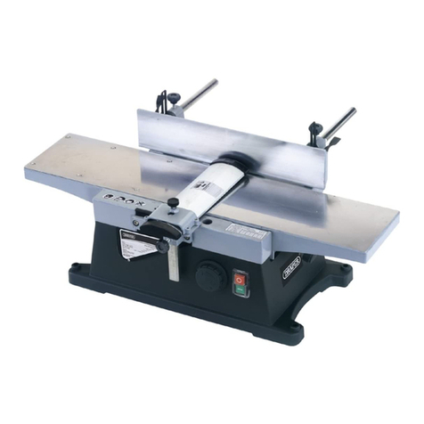
Draper Storm Force PT650SF User manual

IMPORTANT: PLEASE READ THESE INSTRUCTIONS CAREFULLY TO ENSURE THE SAFE AND
EFFECTIVE USE OF THIS PRODUCT.
GENERAL INFORMATION
These instructions accompanying the product are the original instructions. This document is part of the product, keep it
for the life of the product passing it on to any subsequent holder of the product. Read all these instructions before
assembling, operating or maintaining this product.
This manual has been compiled by Draper Tools describing the purpose for which the product has been designed, and
contains all the necessary information to ensure its correct and safe use. By following all the general safety instructions
contained in this manual, it will ensure both product and operator safety, together with longer life of the product itself.
AlI photographs and drawings in this manual are supplied by Draper Tools to help illustrate the operation of the product.
Whilst every effort has been made to ensure the accuracy of information contained in this manual, the Draper Tools
policy of continuous improvement determines the right to make modifications without prior warning.
INSTRUCTIONS FOR
650W 230V
82mm Planer
Stock No.83637 Part No.PT650SF
STORM

1. TITLE PAGE
1.1 INTRODUCTION:
USER MANUAL FOR:
650W 230V PLANER
Stock no. 83637
Part no. PT650SF
1.2 REVISIONS:
As our user manuals are continually updated, users should make sure that they use the very
latest version.
Downloads are available from: http://www.drapertools.com/manuals
DRAPER TOOLS LIMITED WEBSITE: drapertools.com
HURSLEY ROAD PRODUCT HELP LINE: +44 (0) 23 8049 4344
CHANDLER’S FORD GENERAL FAX: +44 (0) 23 8026 0784
EASTLEIGH
HAMPSHIRE
SO53 1YF
UK
1.3 UNDERSTANDING THIS MANUALS SAFETY CONTENT:
WARNING! Information that draws attention to the risk of injury or death.
CAUTION! Information that draws attention to the risk of damage to the product or
surroundings.
1.4 COPYRIGHT © NOTICE:
Copyright © Draper Tools Limited.
Permission is granted to reproduce this publication for personal & educational use only.
Commercial copying, redistribution, hiring or lending is prohibited.
No part of this publication may be stored in a retrieval system or transmitted in any other
form or means without written permission from Draper Tools Limited.
In all cases this copyright notice must remain intact.
Date first published April 2016

2. CONTENTS
3
2.1 CONTENTS
PAGE CONTENT PAGE
1 TITLE PAGE
1.1 INTRODUCTION ....................................................................................................2
1.2 REVISION HISTORY................................................................................................2
1.3 UNDERSTANDING THIS MANUAL .......................................................................2
1.4 COPYRIGHT NOTICE..............................................................................................2
2 CONTENTS
2.1 CONTENTS .............................................................................................................3
3 GUARANTEE
3.1 GUARANTEE ..........................................................................................................4
4 INTRODUCTION
4.1 SCOPE ...................................................................................................................5
4.2 SPECIFICATION ......................................................................................................5
4.3 HANDLING & STORAGE ........................................................................................5
5. HEALTH & SAFETY INFORMATION
5.1 GENERAL SAFETY INSTRUCTIONS ........................................................................6 - 7
5.2 ADDITIONAL SAFETY FOR PLANERS ....................................................................7
5.3 CONNECTION TO THE POWER SUPPLY................................................................8
6. TECHNICAL DESCRIPTION
6.1 IDENTIFICATION ...................................................................................................9
7. UNPACKING & CHECKING
7.1 PACKAGING...........................................................................................................10
7.2 WHAT´S IN THE BOX? ...........................................................................................10
8. SETTING UP THE PLANER
8.1 SETTING THE PLANER ...........................................................................................11
8.2 BLADES ..................................................................................................................11
8.3 ATTACHING THE PARALLEL GUIDE......................................................................11
8.4 ATTACHING THE REBATING DEPTH GUIDE .........................................................11
8.5 FITTING THE DUST EXTRACTION BAG .................................................................11
9. OPERATING THE PLANER
9.1 STARTING THE PLANER......................................................................................... 12
9.2 GENERAL PLANING OPERATIONS ........................................................................12
9.3 CHAMFERING EDGES ............................................................................................12
9.4 REBATING ..............................................................................................................12
9.5 DIRECTION OF ADVANCEMENT ...........................................................................13
9.6 FOOT PARK............................................................................................................13
9.7 IMPROPER USE ......................................................................................................13
10. MAINTENANCE
10.1 BLADE REPLACEMENT/ADJUSTMENT ..................................................................14
10.2 DRIVE BELT REPLACEMENT ..................................................................................15
11. TROUBLESHOOTING
11.1 TROUBLESHOOTING GUIDE..................................................................................16
12. EXPLANATION OF SYMBOLS
12.1 EXPLANATION OF SYMBOLS ................................................................................17
13. DISPOSAL
13.1 DISPOSAL...............................................................................................................18
DECLARATION OF CONFORMITY ..........................................................................................ENCLOSED

4
3. GUARANTEE
3.1 GUARANTEE
Draper
tools have been carefully tested and inspected before shipment and are guaranteed to
be free from defective materials and workmanship.
Should the tool develop a fault, please return the complete tool to your nearest distributor or
contact Draper Tools Limited, Chandler's Ford, Eastleigh, Hampshire, SO53 1YF. England.
Telephone Sales Desk: (023) 8049 4333 or Product Help Line (023) 8049 4344.
A proof of purchase must be provided with the tool.
If upon inspection it is found that the fault occurring is due to defective materials or
workmanship, repairs will be carried out free of charge. This guarantee period covering
parts/labour is 12 months from the date of purchase except where tools are hired out when the
guarantee period is 90 days from the date of purchase. The guarantee is extended to 24 months
for parts only. This guarantee does not apply to normal wear and tear, nor does it cover any
damage caused by misuse, careless or unsafe handling, alterations, accidents, or repairs
attempted or made by any personnel other than the authorised Draper warranty repair agent.
Note: If the tool is found not to be within the terms of warranty, repairs and carriage charges
will be quoted and made accordingly.
This guarantee applies in lieu of any other guarantee expressed or implied and variations of its
terms are not authorised.
Your Draper guarantee is not effective unless you can produce upon request a dated receipt or
invoice to verify your proof of purchase within the guarantee period.
Please note that this guarantee is an additional benefit and does not affect your statutory rights.
Draper Tools Limited.

5
4. INTRODUCTION
4.1 SCOPE
This planer is suitable for planing doors, smoothing off rough edges and trimming/shaping
timber. It is intended for domestic and light commercial use only. Any other application is
considered misuse.
4.2 SPECIFICATION
Stock no ........................................................................................................................... 83637
Part no .......................................................................................................................... PT650SF
Motor:
Rated voltage ...................................................................................................... 230V~
Rated frequency ................................................................................................... 50Hz
Rated input ......................................................................................................... 650W
Revolutions per minute (no load) ............................................................. 17,500min-1
Cutting capacity:
Depth.............................................................................................................. 0 – 2.0mm
Width..................................................................................................................... 82mm
Sole plate length........................................................................................................... 234mm
Sound pressure level ................................................................................................. 91.0dB(A)
Sound power level .................................................................................................... 102dB(A)
Vibration level .................................................................................................................4.7m/s2
Weight ............................................................................................................................ 2.80kg
4.3 HANDLING & STORAGE
The environment will have a negative result on its operation if you are not careful. If the air
is damp, components will rust. If the machine is unprotected from dust and debris;
components will become clogged: And if not cleaned and maintained correctly or regularly
the machine will not perform at its best.

6
5. HEALTH & SAFETY INFORMATION
5.1 GENERAL SAFETY INSTRUCTIONS
General Power Tools Safety Warnings
Warning! Read all instructions. Failure to follow all instructions listed below may result in
electric shock, fire and/or serious injury.
Save all warnings and instructions for future reference.
The term “power tool” in the warnings refers to your mains operated (corded) power tool or
battery operated (cordless) power tool.
1) Work area safety
a) Keep work area clean and well lit. Cluttered or dark areas invite accidents.
b) Do not operate power tools in explosive atmospheres, such as in the presence of
flammable liquids, gases or dust. Power tools create sparks which may ignite the dust
or fumes.
c) Keep children and bystanders away while operating a power tool. Distractions can
cause you to lose control.
2) Electrical Safety
a) Power tool plugs must match the outlet. Never modify the plug in any way. Do not
use any adapter plugs with earthed (grounded) power tools. Unmodified plugs and
matching outlets will reduce risk of electrical shock.
b) Avoid body contact with earthed or grounded surfaces such as pipes, radiators,
ranges and refrigerators. There is an increased risk of electric shock if your body is
earthed or grounded.
c) Do not expose power tools to rain or wet conditions. Water entering a power tool
will increase the risk of electric shock.
d) Do not abuse the cord. Never use the cord for carrying, pulling or unplugging the
power tool. Keep cord away from heat, oil, sharp edges or moving parts. Damaged or
entangled cords increase the risk of electric shock.
e) When operating a power tool outdoors, use an extension cord suitable for outdoor
use. Use of a cord suitable for outdoor use reduces the risk of electric shock.
f) If operating a power tool in a damp location is unavoidable, use a residual current
device (RCD) protected supply. Use of an RCD reduces the risk of electric shock.
3) Personal Safety
a) Stay alert, watch what you are doing and use common sense when operating a
power tool. Do not use a power tool while you are tired or under the influence of
drugs, alcohol or medication. A moment of inattention while operating power tools
may result in serious personal injury.
b) Use personal protective equipment. Always wear eye protection. Protective
equipment such as dust mask, nonskid safety shoes, hard hat, or hearing protection
used for appropriate conditions will reduce personal injuries.
c) Prevent unintentional starting. Ensure the switch is in the off position before
connecting to power source and/or battery pack, picking up or carrying the tool.
Carrying power tools with your finger on the switch or energising power tools that
have the switch on invites accidents.
d) Remove any adjusting key or wrench before turning the power tool on. A wrench or
a key left attached to a rotating part of the power tool may result in personal injury.
e) Do not overreach. Keep proper footing and balance at all times. This enables better
control of the power tool in unexpected situations.
f) Dress properly. Do not wear loose clothing or jewellery. Keep your hair, clothing and
gloves away from moving parts. Loose clothes, jewellery or long hair can be caught in
moving parts.

7
5. HEALTH & SAFETY INFORMATION
g) If devices are provided for the connection of dust extraction and collection facilities,
ensure these are connected and properly used. Use of dust collection can reduce dust
related hazards.
4) Power Tool Use And Care
a) Do not force the power tool. Use the correct power tool for your application. The
correct power tool will do the job better and safer at the rate for which it was
designed.
b) Do not use the power tool if the switch does not turn it on and off. Any power tool
that cannot be controlled with the switch is dangerous and must be repaired.
c) Disconnect the plug from the power source and/or the battery pack from the power
tool before making any adjustments, changing accessories, or storing power tools.
Such preventive safety measures reduce the risk of starting the power tool
accidentally.
d) Store idle power tools out of the reach of children and do not allow persons
unfamiliar with the power tool or these instructions to operate the power tool.
Power tools are dangerous in the hands of untrained users.
e) Maintain power tools. Check for misalignment or binding of moving parts, breakage
of parts and any other condition that may affect the power tools operation. If
damaged, have the power tool repaired before use. Many accidents are caused by
poorly maintained power tools.
f) Keep cutting tools sharp and clean. Properly maintained cutting tools with sharp
cutting edges are less likely to bind and are easier to control.
g) Use the power tool, accessories and tool bits etc., in accordance with these
instructions, taking into account the working conditions and the work to be
performed. Use of the power tool for operations different from intended could result
in a hazardous situation.
5) Service
a. Have your power tool serviced by a qualified repair person using only identical
replacement parts. This will ensure that the safety of the power tool is maintained.
5.2 ADDITIONAL SAFETY FOR PLANERS
Wait for the cutter to stop before setting the tool down. An exposed rotating cutter may
engage the surface leading to possible loss of control.
Hold the power tool by the handle only, in case the cutter contacts its own cord.
Cutting a “live” wire may make exposed metal parts of the power tool “live” and could give
the operator an electric shock.
Use clamps or another practical way to secure and support the workpiece to a stable
platform. Hold the work by your hand or against the body leaves it unstable and may lead to
loss of control.

8
5. HEALTH & SAFETY INFORMATION
5.3 CONNECTION TO THE POWER SUPPLY
Make sure the power supply information on the machine’s rating plate are compatible with
the power supply you intend to connect it to.
This product comes supplied with a UK standard 3 pin plug fitted. It is designed for
connection to a domestic power supply rated at 230V AC.
This appliance is Class II† and is designed for connection to a power supply matching that
detailed on the rating label and compatible with the plug fitted.
If an extension lead is required, use an approved and compatible lead rated for this
appliance. Follow all the instruction supplied with the extension lead.
†Double insulated : This product requires no earth connection as supplementary insulation
is applied to the basic insulation to protect against electric shock in the event of failure of
the basic insulation.
Apart from replacing the fuse in the plug, no other electrical work is recommended on this
machine.

9
6. TECHNICAL DESCRIPTION
6.1 IDENTIFICATION
Trigger switch.
Trigger release button.
Hand grip.
Power cable.
Rear sole plate.
Drive belt cover.
Front sole plate.
Depth regulation knob.
Dust outlet port.
Blade drum.
Chamfer guide 'V' groove.
Rebating depth guide attachment knob.
Blade spanner on-board storage.
Parallel guide attachment knob.
Foot park.
Rebate depth guide.

10
7. UNPACKING & CHECKING
7.1 PACKAGING
Carefully remove the planer from the packaging and examine it for any sign of damage that
may have happened during shipping. Lay the contents out and check them against the parts
shown below. If any part is damaged or missing; please contact the Draper Help Line (the
telephone number appears on the Title page) and do not attempt to use the planer.
The packaging material should be retained at least during the guarantee period: in case the
machine needs to be returned for repair.
Warning! Some of the packaging materials used may be harmful to children. Do not leave
any of these materials in the reach of children.
If any of the packaging is to be thrown away, make sure they are disposed of correctly;
according to local regulations.
7.2 WHAT´S IN THE BOX?
As well as the planer; there are several parts not fitted or attached to it.
Parallel guide.
Rebating depth guide.
Blade adjustment spanner.
Dust extraction bag.

11
8. SETTING UP THE PLANER
NOTE: Remove the plug from the socket before
carrying out adjustment, servicing or maintenance.
8.1 SETTING THE PLANER – FIG. 1
Before initial startup and at regular intervals, check the
blade assembly is secure and adjusted correctly.
To adjust the depth of cut between 0 and 2.0mm rotate
the depth regulation knob accordingly.
8.2 BLADES
This planer is equipped with double edged H.S.S. blades.
For optimal long term performance, periodically check
the condition of the blades and, if necessary replace
them.
Note: Further instructions for adjusting or replacing the
blades can be found in chapter 10.1 – Blade
Replacement/Adjustment on page 14.
Only use perfectly sharpened blades!
Only use recommended blades and blade holders.
8.3 ATTACHING THE PARALLEL GUIDE – FIG. 2
The optional parallel guide is fitted with an
adjustable width setting,useful for greater control and
accuracy when planing and is secured to the body of the
planer via the attachment knob .
8.4 ATTACHING THE REBATING DEPTH GUIDE
– FIG. 3
The rebating guide is secured to the body of the
planer via the attachment knob .
8.5 FITTING THE DUST EXTRACTION BAG
– FIG. 4
Inhalation of dust particles can be detrimental to
health. For this reason a dust extraction bag has
been provided and must be used with the machine at all
times.
Warning! All wood dust (including dust from
composites like chipboards and fibreboards, etc.) is
hazardous to health; it can affect the nose, the
respiratory system and the skin. For example MDF
(medium density fibreboard) which contains
formaldehyde is a known carcinogen. In addition to the
above measure a correctly fitted dust mask, suitable for
the activity and in accordance to the relevant standard,
must be worn. For work activities involving exposure to
the fine wood dust, a mask rated to at least FFP2 should
be used.
The dust bag is fitted to the planer via the plastic
collar which slides onto the dust outlet port .
FIG.1
FIG.2
FIG.2
FIG.3
FIG.4

12
9. OPERATING THE PLANER
9.1 STARTING THE PLANER – FIG. 5
The on/off switch is fitted with a safety button
so that it is not possible to start the planer by accident.
To start the planer, press the safety button then
depress the on/off switch .
IMPORTANT: Before using the machine on any work or
scrap pieces of timber, let the blade run for a few
minutes to observe for vibration etc.
Wait for the cutter to stop before settling the tool
down. An exposed cutter may engage the surface
leading to possible loss of control and serious injury.
9.2 GENERAL PLANING OPERATIONS – FIG. 6
Place the front sole plate on the workpiece. With the
depth set, start the planer and allow the blades to run
to full speed. Move the machine across the workpiece,
ensuring the pass is smooth, even and gentle to obtain
the optimum cut.
Note: Moving the planer too fast or backwards will
cause the machine to bounce and produce a poor finish.
9.3 CHAMFERING EDGES – FIG. 7
The V-groove in the front sole plate is used for
chamfering. Place the planer with the V-groove on the
edge of the workpiece , push the planer slowly and
evenly forward along the edge.
9.4 REBATING – FIG. 8
Set the rebate depth guide and secure with the
locking knob .
– Begin cutting.
FIG.5
FIG.6
FIG.3FIG.3
FIG.7
FIG.8

13
9. OPERATING THE PLANER
9.5 DIRECTION OF ADVANCEMENT – FIG. 9
The planer advancement direction should always be as
shown.
The roller rotation direction is indicated by an arrow on
the belt cover.
9.6 FOOT PARK – FIG. 10
Prevents damage to the work surfaces when setting
planer down. Fold down lug to ensure planer stands
proud of surface.
9.7 IMPROPER USE
The functions and use of this planer are those
exclusively indicated in this manual.
Wait for complete run-down before putting the tool
aside.
Replacement blades are available from your local
Draper stockist.
Important: The blades must always be reversed or
replaced as a pair.
FIG.9
FIG.10

14
10. MAINTENANCE
10.1 BLADE REPLACEMENT/ADJUSTMENT –
FIGS. 11 – 14
Note: only use sharp blades.
Switch off the power supply and disconnect the mains
lead before carrying out any maintenance operations.
Warning! The blades are extremely sharp, so care must
be taken at all times.
Using the supplied blade spanner , loosen the bolts
which will release the tension on the blade. When
the blade is loose slide it out.
Loosen the two grub screws (Fig.12) anticlockwise
until they are flush with the surface of the clamp block
. Insert the new blade making sure of the correct
orientation (inset fig.13) ie. the groove down the back
of the blade is NOT against the clamp block.
Adjust the bolts to grip the blade loosely so that it stays
in place, but still allowing ease of movement for setting
up the blade height/level.
Adjust the front sole plate so that it is lower than the
rear plate to avoid interference.
Place a straight edge across the rear sole plate and
cutter block.
By screwing the grub screws clockwise equally, raise the
blade up gradually. Keep checking the blade height by
moving the cutter block round by hand to see if the
blade scrapes on the straight edge. Set the blade so that
it just touches the straight edge (Fig.14). Make this
check at three points across the blade to ensure a
correct and equal level is achieved. When adjustment is
complete, one end of the blade must be in line with the
rebating side of the rear sole plate.
Warning! After having completed this operation,
ensure that the blade and blade support are securely
fastened in the cutter block, if not, serious accidents
may occur.
Warning! Due to the forces and vibration which are
experienced by the cutter block, it is recommended that
a suitable thread locking compound be applied to the
blade adjustment grub screws. For this reason it is also
important before each use to inspect the blade set up.
FIG.11
FIG.13
FIG.14
FIG.12

15
10. MAINTENANCE
10.2 DRIVE BELT REPLACEMENT – FIG. 15
Switch off the power supply and disconnect the mains lead
before carrying out any maintenance operations. To
replace the drive belt, remove cover to access the belt
and pulleys. Simply replace the belt and refit the cover.
FIG.15

16
11. TROUBLESHOOTING
11.1 TROUBLESHOOTING GUIDE
NOTE: Remove the plug from the socket before carrying out adjustment, servicing or
maintenance.
Motor does not
start.
1. Fuse.
3. Unsure.
Machine will not cut
or leaves a rough
finish.
Loss of drive. 1. Worn or broken drive
belt.
1. Replace belt††.
Machine does not
cut to the correct
depth.
1. Blade adjustment
wrong.
1. Adjust blades.
1. Replace blades†.1. Blunt blades.
2. Wood is wet. 2. Leave wood out to dry.
† Replacement blades can be obtained from your local Draper stockist.
†† Replacement drive belts can be obtained from your local Draper stockist.
2. Have carbon brushes replaced by an
authorised service centre.
1. Replace time delay fuse or reset
circuit breaker.
3. Contact an authorised service centre.
2. Brushes worn.
PROBLEM POSSIBLE CAUSE REMEDY

17
12. EXPLANATION OF SYMBOLS
12.1 EXPLANATION OF SYMBOLS
Warning!
Wear dust mask.
Warning!
Read the instruction manual
Warning!
Wear ear defenders.
WEEE
Do not dispose of Waste Electrical
& Electronic Equipment in with
domestic rubbish
Class II construction
(Double insulated).
Warning!
Wear suitable eye/face
protection.
Reference to
‘Welding’
removed from
eye/face
protection icon
wording.
05/08/16 CH

18
13. DISPOSAL
13.1 DISPOSAL
– At the end of the machine’s working life, or when it can no longer be repaired, ensure
that it is disposed of according to national regulations.
– Contact your local authority for details of collection schemes in your area.
In all circumstances:
• Do not dispose of power tools with domestic waste.
• Do not incinerate.
• Do not abandon in the environment.
• Do not dispose of WEEE*
as unsorted municipal waste.
* Waste Electrical & Electronic Equipment.

19
NOTES

CONTACTS
- DRAPER TOOLS LIMITED,
Hursley Road, Chandler's Ford,
Eastleigh, Hampshire. SO53 1YF. U.K.
- Help Line: (023) 8049 4344
- Sales Desk: (023) 8049 4333
- General Enquiries: (023) 8026 6355
- Service/Warranty Repair Agent
For aftersales servicing or warranty repairs, please
contact the Draper Tools Help Line for details of an
agent in your local area.
YOUR DRAPER STOCKIST
RDCH0816
drapertools.com
This manual suits for next models
3
Table of contents
Other Draper Planer manuals
Popular Planer manuals by other brands

Makita
Makita 2012NB instruction manual

King Industrial
King Industrial KC-235PM instruction manual

Baileigh Industrial
Baileigh Industrial IP-156 Operator's manual

Hitachi
Hitachi P 20SA2 Handling instructions

Vulcan Concept
Vulcan Concept VMG601 operating instructions

Power Tec
Power Tec PL1251 owner's manual