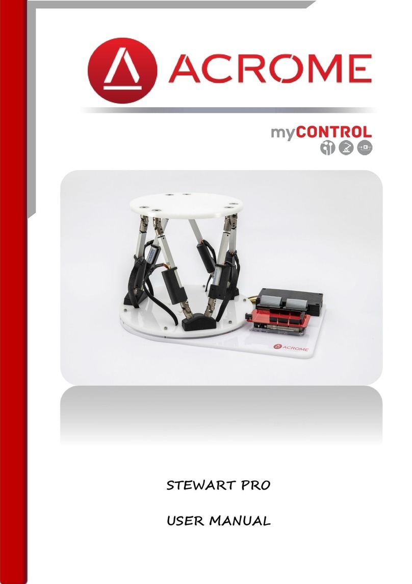
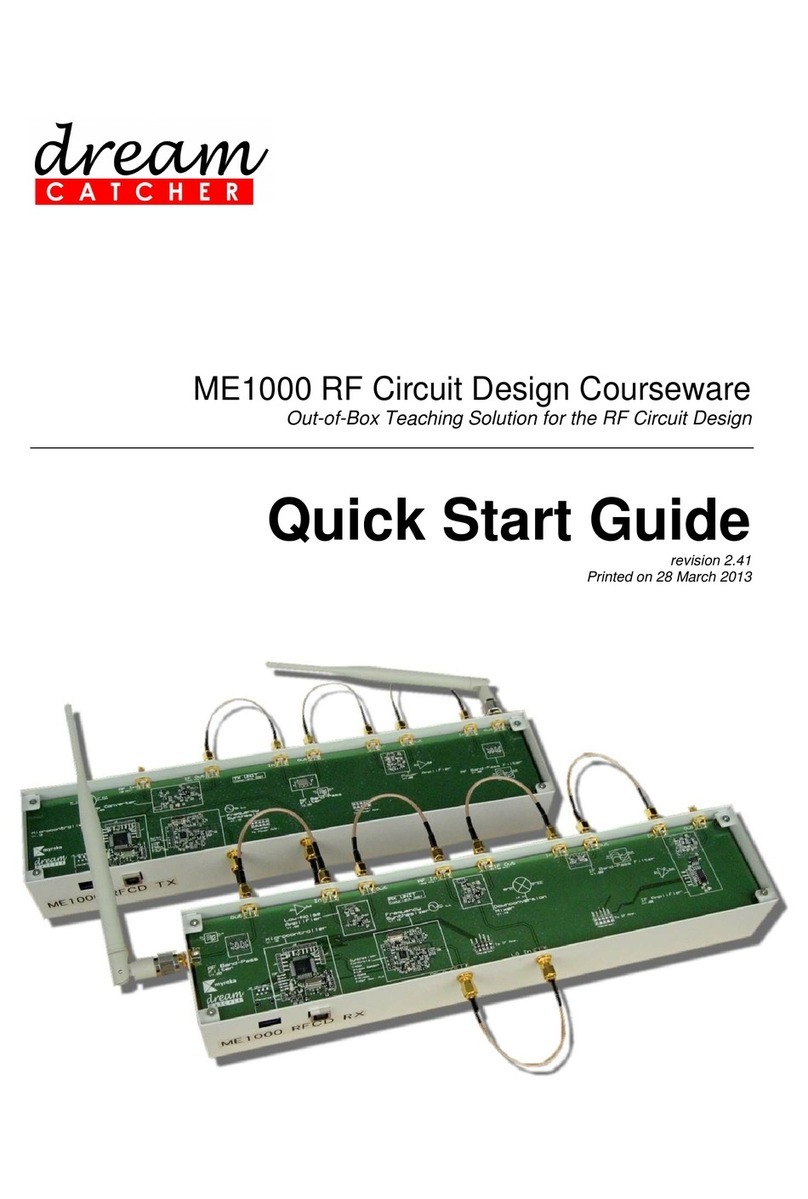
Dream Catcher ME1400 EMI User manual

ME1400 EMI and EMC Courseware
Ready-to-Teach package for EMI and EMC
Quick Start Guide
revision 2.02
Printed on 24 January 2019

ME1400 EMI and EMC
Quick Start Guide - 2/13
CAUTION —ESD!
THIS PRODUCT CONTAINS ELECTRONIC COMPONENTS SENSITIVE TO
ELECTROSTATIC DISCHARGE.
An electrostatic discharge generated by a person or an object coming in contact with
the electrical components may damage or destroy the product. To avoid the risk of
electrostatic discharge, please observe the handling precautions and
recommendations contained in the EN100015-1 standard. Do not connect or
disconnect the device while it is being energized.
WARNING:
CHANGES OR MODIFICATIONS NOT EXPRESSLY APPROVED BY THE PARTY
RESPONSIBLE FOR COMPLIANCE WITH THE EMC RULES COULD VOID THE
USER’S AUTHORITY TO OPERATE THE PRODUCT.

ME1400 EMI and EMC
Quick Start Guide - 3/13
Table of Contents
Table of Contents....................................................................................................................................3
DreamCatcher Courseware Customer Login Guide...............................................................................4
1. Quick Setup and Verification...............................................................................................................6
2. Support and Warranty.......................................................................................................................10
Appendix: Technical Specifications ......................................................................................................11
Revision History....................................................................................................................................12
Contact Us.............................................................................................................................................13

ME1400 EMI and EMC
Quick Start Guide - 4/13
DreamCatcher Courseware Customer Login
Guide
1. Go to the DreamCatcher Courseware website at http://dreamcatcher.asia/cw/
2. Click the Product Registration / Download link at the bottom left corner of the page.
3. If you are new customer, skip to step 5. If you are a returning customer, proceed to step 4.
4. If you are a returning customer, click Continue under the LOGIN section to login.
NOTE: If you have created your DreamCatcher account before the 1st of September 2017,
you will receive an e-mail request to reset your password. If you do not receive the password
reset e-mail within a few minutes of logging in, please check your Junk E-mail folder just in
case the password reset e-mail got delivered there instead of your inbox. Follow the
instructions in the password reset e-mail to reset your password and continue logging in.
Skip to step 6 to complete the log in procedure.
5. If you are a new customer, click Continue under the CREATE ACCOUNT section to create a
new account.
Fill in the New Account form and click SIGN UP to submit your registration.

ME1400 EMI and EMC
Quick Start Guide - 5/13
6. After successfully logging in, your DASHBOARD page appears.
A. EDIT PROFILE
Update your user profile
B. REGISTER NEW PRODUCT
Register a new product with the given product key
NOTE: Contact your local sales representative if you need further assistance.
C. PRODUCTS DOWNLOADS
Download the registered product’s contents and materials
NOTE: Products downloads are made available only for registered products. Click
REGISTER NEW PRODUCT to register your product first.
D. WARRANTY INFORMATION
View your product’s warranty expiry date

ME1400 EMI and EMC
Quick Start Guide - 6/13
1. Quick Setup and Verification
1.1 Basic Setup and Test Procedure for the ME1400 Training Kit
The following steps demonstrate a basic setup and test procedure using the ME1400 training kit:
Test 1: Measurement of a 10 MHz Digital Pulse and Its Radiated Emissions
Test 2: Measurement of a 10 MHz Sine Wave Output in the Presence of Motor Noise
IMPORTANT
•The training kit can be damaged by excessive power levels from instruments. Please adhere
strictly to the power levels recommended in the instructions.
•Turn off the training kit when not in use.
Test 1: Measurement of a 10 MHz Digital Pulse and Its Radiated Emissions
Figure 1 –Experimental Setup for the Measurement of a 10 MHz Digital Pulse
1. Supply a 5 V input voltage to the EMI Source Module.
2. Switch S1 to the ‘ON’ position to power up the 10 MHz Digital Pulse source.
3. Use a digital oscilloscope to probe test point TP3 with respect to GND. You should observe a
10 MHz digital pulse. Measure the rise time of the digital pulse.
4. Switch S1 to the ‘OFF’ position.
5. Connect an RF coaxial cable from J2 (Medium-speed Output) to J6 (Digital Buffer with
Termination with No GND Plane) as shown in Figure 1.
6. Power on the N9912A FieldFox RF Analyzer.
1
2
5
3
9
9
EMC probe
10

ME1400 EMI and EMC
Quick Start Guide - 7/13
7. Set the N9912A FieldFox RF Analyzer to operate in the Spectrum Analyzer mode. Select the
start and stop frequencies, and other settings according to the following configuration:
Mode : SA (Spectrum Analyzer)
Start Frequency : 10 MHz
Stop Frequency : 400 MHz
8. Connect the EMC probe (H-field Probe) to the RF In port of the N9912A FieldFox RF Analyzer
using an RF coaxial cable.
9. Switch S1 and S2 to the ‘ON’ position to power on the Digital Pulse Output and Digital Buffer
sections.
10. Place the EMC probe on top of the digital buffer trace that is being tested. Slowly move the
EMC probe around the trace and observe the spectrum displayed on the screen of the
N9912A FieldFox RF Analyzer. Describe your observation.
11. Switch S1 and S2 to the ‘OFF’ position, and turn off the power supply.
N9912A Setting: “[ ]”: Hardkey; “{ }”: Softkey
Set Mode to SA measurement: [Mode] > {SA}
Set Start Frequency to 10 MHz: [Freq/Dist] > {Start} > [10] > {MHz}
Set Stop Frequency to 400 MHz: [Freq/Dist] > {Stop} > [400] > {MHz}
Set output power level to LOW: [Meas Setup 4] > {Output Power} > {Low}
Scale: [Scale/Amptd] > {Autoscale}
Perform Calibration: Normalization

ME1400 EMI and EMC
Quick Start Guide - 8/13
Test 2: Measurement of the 10 MHz Sine Wave Output in the Presence of Motor Noise
Figure 2 –Experimental Setup for the Measurement of a 10 MHz Sine-wave Output in the
Presence of Motor Noise
1. Supply a 5 V input voltage to the EMI Source Module.
2. Switch S5 to the ‘ON’ position to turn on the 10 MHz Sine Wave Oscillator.
3. Use a digital oscilloscope to probe test point TP11 with respect to GND, which is the output of
the 10 MHz Sine Wave Oscillator. You should observe a pure sinusoidal waveform.
4. Next, switch S4 to the ‘ON’ position to turn on the brushed DC motor. Observe the output of
the Sine Wave Oscillator in the presence of motor noise. Describe the differences as
compared to the observations made in Step 3.
5. Switch S4 and S5 to the ‘OFF’ position.
6. Connect the output of the 10 MHz Sine Wave Oscillator (J8) to the RF In port of the N9912A
FieldFox RF Analyzer using an RF coaxial cable.
7. Power on the N9912A FieldFox RF Analyzer.
8. Set the N9912A FieldFox RF Analyzer to operate in the Spectrum Analyzer mode. Select the
start and stop frequencies, and other settings according to the following configuration:
Mode : SA
Start Frequency : 5 MHz
Stop Frequency : 15 MHz
N9912A Setting: “[ ]”: Hardkey; “{ }”: Softkey
Set Mode to SA measurement: [Mode] > {SA}
Set Start Frequency to 5 MHz: [Freq/Dist] > {Start} > [5] > {MHz}
Set Stop Frequency to 15 MHz: [Freq/Dist] > {Stop} > [15] > {MHz}
Set output power level to LOW: [Meas Setup 4] > {Output Power} > {Low}
Scale: [Scale/Amptd] > {Autoscale}
Perform Calibration: Normalization
1
2
3
4

ME1400 EMI and EMC
Quick Start Guide - 9/13
9. Switch S5 to the ‘ON’ position to turn on the 10 MHz Sine Wave Oscillator. Observe the
spectrum of the sinusoidal signal.
10. Next, Switch S4 to the ‘ON’ position to turn on the brushed DC motor. Observe the spectrum
and describe the differences as compared to your observations in Step 9.
11. Switch S4 and S5 to the ‘OFF’ position, and turn off the power supply.

ME1400 EMI and EMC
Quick Start Guide - 10/13
2. Support and Warranty
2.1 Terms and Conditions
This courseware product contains scholarly and technical information and is protected by copyright
laws and international treaties. No part of this publication may be reproduced by any means, be it
transmitted, transcribed, photocopied, stored in a retrieval system, or translated into any language in
any form, without the prior written permission of Acehub Vista Sdn. Bhd.
The use of the courseware product and all other products developed and/or distributed by Acehub
Vista Sdn. Bhd. are subject to the applicable License Agreement.
For further information, see the Courseware Product License Agreement.
To retrieve the password for installation of the provided materials and software as well as the model
answers and solutions for lab sheets, please register yourself at http://dreamcatcher.asia/cw under
the Product Registration menu using the product key provided with the teaching courseware.
2.2 Product Warranty
•Acehub Vista Sdn. Bhd. warrants that its products sold will at the time of shipment be free
from defects in material and workmanship and will conform to Acehub Vista Sdn. Bhd.'s
applicable specifications.
•If Acehub Vista Sdn. Bhd. receives notice of a defect or non-conformance during the one
year warranty period, Acehub Vista Sdn. Bhd. will, at its option, repair or replace the affected
product. Buyer will pay shipping expenses for return of such product to Acehub Vista Sdn.
Bhd. or its authorized reseller. Acehub Vista Sdn. Bhd. or its authorized reseller will pay
expenses for shipment of the repaired or replacement product.
•This warranty shall not apply to any products Acehub Vista Sdn. Bhd. determines have been,
by Buyer or otherwise, subject to operating and/or environmental conditions in excess of the
maximum values established in applicable specifications, or have been subject to
mishandling, misuse, neglect, improper testing, repair, alteration, damage, assembly, or
processing that alters physical or electrical properties.
•In no event will Acehub Vista Sdn. Bhd. be liable for any incidental or consequential
damages.
•This warranty extends to Buyer only and not to Buyer's customers or users of Buyer's
products and is in lieu of all other warranties whether expressed, implied, or statutory
including implied warranties of merchantability of fitness.
•For technical support and warranty, email cw.support@dreamcatcher.asia
ME1400 EMI and EMC
Quick Start Guide - 11/13
Appendix: Technical Specifications
ME1400 –EMI Source Module
Amplitude
Frequency
Remarks
Oscillators
3-speed Digital Pulse
3.0 Vpp ± 0.5 V (into 50 Ω)
10 MHz ± 50 ppm
Sine wave oscillator
550 mVpp ± 50 mV (into 50 Ω)
10 MHz ± 50 ppm
Square wave oscillator
3.5 Vpp ± 0.5 V (into 100 Ω)
50 MHz ± 50 ppm
General
Input voltage
5 Vdc
Input current
0.25 A[1] (typical)
[1] When the DC motor is turned on. When the DC motor is turned off, typical current consumption is less than 10 mA.

ME1400 EMI and EMC
Quick Start Guide - 12/13
Revision History
Revisions
Date
Notes
2.01
NA
Initial document.
2.02
NA
Added:
DreamCatcher Courseware Customer Login Guide
2.03
23-Jan-19
Changed “near-field probe” to “EMC probe”

ME1400 EMI and EMC
Quick Start Guide - 13/13
Contact Us
Contact Us
Acehub Vista Sdn Bhd (785702-P)
A member of the DreamCatcher group
70-03-79,D’Piazza Mall, Jalan
Mahsuri, Bayan Lepas, 11900
Penang, Malaysia.
All rights reserved. No part of this document
may be reproduced or transmitted in any form
or by any means, electronic, mechanical,
photocopying, recording, or otherwise,
without prior written permission of Acehub
Vista Sdn. Bhd.
Every effort has been made to ensure that
the information in this manual is accurate.
Acehub Vista Sdn. Bhd. is not responsible for
printing or clerical errors.
Trademark Acknowledgements
DreamCatcherTM is the trademark of Dream
Catcher Consulting Sdn. Bhd.
Microsoft and Windows are trademarks of
Microsoft Corporation in the United States
and/or other countries. All other copyrights
and trademarks belong to their respective
owners.
© 2019 Acehub Vista Sdn. Bhd.
This manual suits for next models
1
Table of contents
Other Dream Catcher Educational Equipment manuals
Popular Educational Equipment manuals by other brands

Imagineering Clubs
Imagineering Clubs MORSE KEY & BUZZER Mk 2 instructions

Silicon Solar
Silicon Solar EDUSOL-AVD-BEGINNERLEVEL Assembly manual

Pitsco Education
Pitsco Education Desk Jockey user guide

Velleman
Velleman KNS7 user manual

OPEN DOOR DESIGN
OPEN DOOR DESIGN PPT Assembly instructions

Enabling Devices
Enabling Devices 5060 user guide