INDUSTRIES, INC.
4 | P a g e
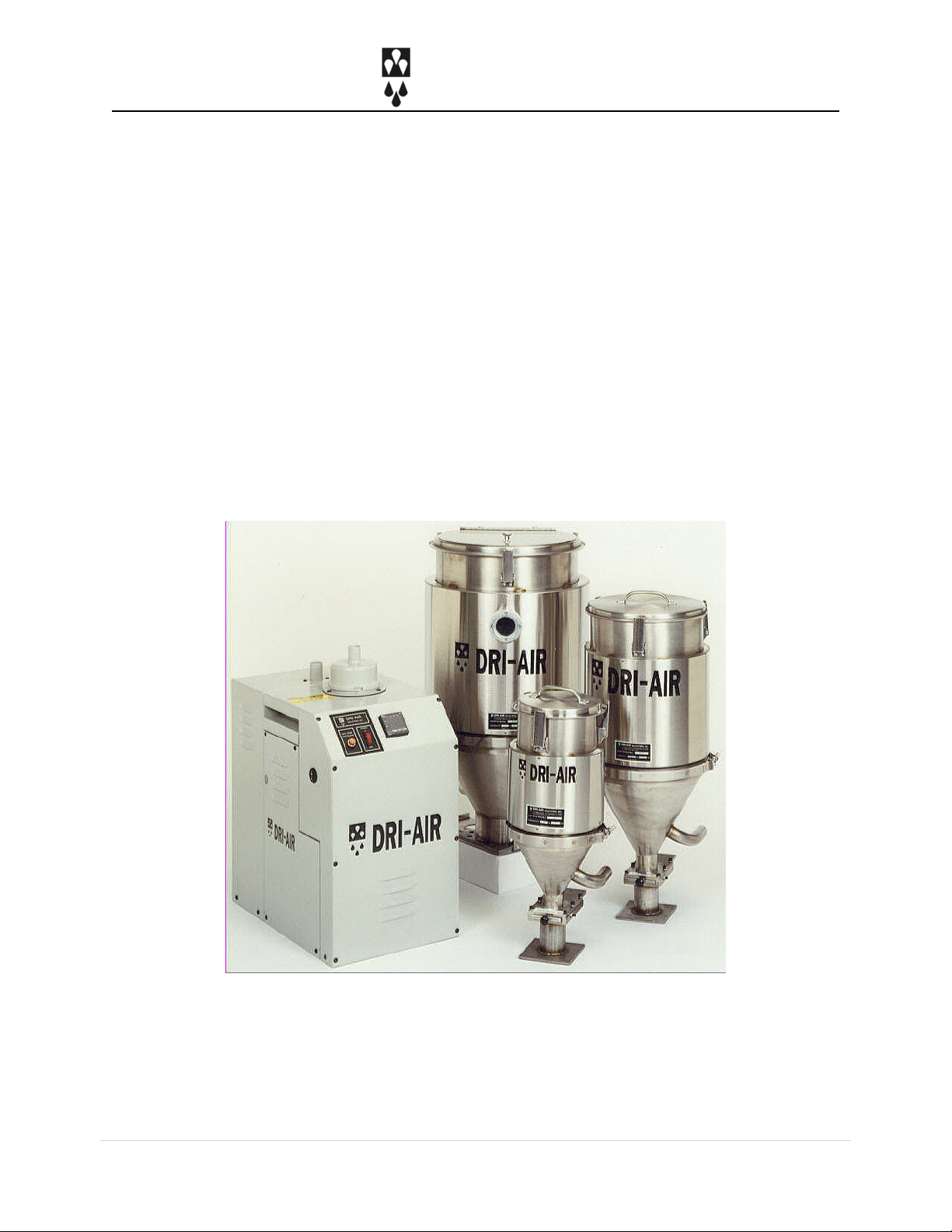
DRYER
DESCRIPTION
The ARID-X10D dryer is a fully portable dryer
designed to dry hygroscopic resins quickly and
efficiently. It is ideal for insert molders and
laboratory applications, or where production
rates are 10 lbs. /hr. or less.
The ARID-X10D dryer is available in 110 volt and
230 volt models. The power requirements for the
110 volt model are a voltage range of 105-130v
AC at 50/60 Hz., single phase with a 20 amp current
rating and the 230 volt model requires a range 220-
250v AC at 50/60 Hz., single phase with a 10 amp
current rating.
Dryer process operating temperatures are 140
degrees F (minimum) to 350 degrees F
(maximum) with an accuracy of +/- 3 degrees.
When the drying temperature is 275 degrees F or
higher, it is necessary to install a water cooled
heat exchanger on the return hose of the dryer to
ensure maximum dryer efficiency. If you do not
have a heat exchanger and will be operating 275
degrees F or higher, please contact the factory for
heat exchanger pricing.
Regeneration Cycle
The ARID-X10D utilizes our HP4-X dual
desiccant bed design that provides a constant
supply of dry air to the material hopper.
While one bed is removing moisture from the
process air stream, the other bed is being
regenerated. The entire process is controlled by
either an ELC factory programmed or our
advanced dry-control microprocessor. When a
regenerated bed completes this cycle, the zone
valve switches the air stream and the newly
regenerated bed is now used for drying the
process air. The saturated bed is then regenerated,
repeating the cycle. Please see the Regeneration
Cycle Diagram on page 8.
The airflow design of the ARID-X/HP4-X dryers
makes the regeneration cycle more efficient