Dri-Air Industries HP4-X 400 - 750 User manual

DRI-AIR INDUSTRIES, INC.
OPERATING MANUAL - HP4-X 400-750 FM DRYERS
Revision 10/8/02 Page 1
HP4-X 400 - 750
FLOOR MOUNT DRYER
OPERATING MANUAL

DRI-AIR INDUSTRIES, INC.
OPERATING MANUAL - HP4-X 400-750 FM DRYERS
Revision 10/8/02
Page 2
DRI-AIRINDUSTRIES, INC.
16 THOMPSON ROAD
P.O. BOX 1020
EAST WINDSOR, CT 06088-1020
Tel. (860) 627-5110
FAX (860) 623-4477
Internet http://www.dri-air.com
e-mail: sales@dri-air.com

DRI-AIR INDUSTRIES, INC.
OPERATING MANUAL - HP4-X 400-750 FM DRYERS
Revision 10/8/02 Page 3
CONTENTS
DRYER OPERATION/FEATURES---------------------------4
AIR FLOW SCHEMATIC FOR HP4-X DRYER -----------6
DRYER CYCLE DIAGRAM ------------------------------------7
INSTALLATION PROCEDURE ------------------------------- 8
Electrical Connection --------------------------------------- 8
Check for correct motor rotation -------------------------8
Compressed Air Connection------------------------------ 8
START-UP PROCEDURE -------------------------------------9
Set Temperature: --------------------------------------------9
DRYER OPERATION-TROUBLE SHOOTING --------- 10
DRYER OPERATION-DETAILED DIAGNOSIS -------- 11
DRI-AIR ZONE VALVE --------------------------------------- 12
PARTS LIST----------------------------------------------------- 13

DRI-AIR INDUSTRIES, INC.
OPERATING MANUAL - HP4-X 400-750 FM DRYERS
Revision 10/8/02
Page 4
The HP4-X 400/500/750 dryer series is a four bed dryer
design that is ideal for use on large molding press or extrusion
applications. This large capacity dryer combines our patented
desiccant tower design and state of the art microprocessor
controls to provide a constant supply of dry air to the material
hopper. Material drying is controlled by utilizing one zone for
removing moisture from the process air, while regenerating
the other by heating the desiccant to a high temperature.
Once the regenerated beds cool down, the Zone Valve
switches the airflow, and the newly regenerated beds are used
to desiccate the process air stream. The saturated beds are
now regenerated in the same manner, completing the
regeneration cycle. The cycle is depicted Page 7.
The airflow design of the HP4-X dryers makes the
regeneration cycle more efficient because we utilize a small
amount of the desiccated process air rather than ambient air
to regenerate the desiccant bed. This reduces the impact of
the high moisture content of the ambient air, which would
contaminate the desiccant bed, and allows the dryer to attain
a lower dew point. Please see the Air Flow Schematic on
Page 6.
HP4-X Design
Our patented HP4-X design incorporates 4 double-stacked
desiccant beds . This nearly doubles the amount of desiccant
available for drying the process air stream, and because of the
tower design, the dryer is able to regenerate the desiccant in
the same time as our ARID-X series. This allows the dryer to
operate in very high humidity conditions without affecting the
process air dew point. In fact, this design produces dew point
levels of – 40’ to -80’ C for faster more complete drying of your
material.
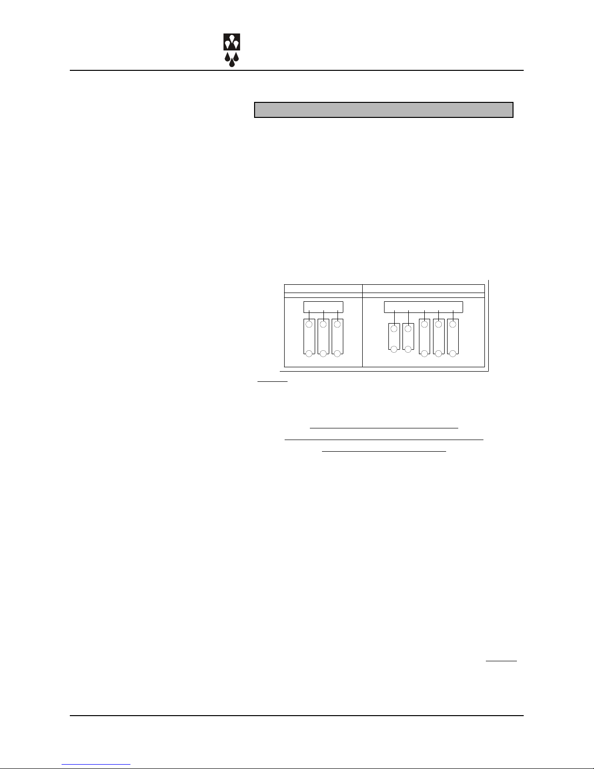
Unique to the HP4-X 400/500/750 disiccant bed design is the
use of two sets of desiccant towers per zone. The first tower
in each Zone Set is the regeneration cycle “control tower”,
while the second tower of the Zone Set is “slaved” off the first.
Please see the Air Flow Diagram on Page 7.
Hopper Design
These dryers are designed to be used with our large capacity
1000, 1500, and 2000 lb. hoppers. Dri-Air’s ”all stainless”
hopper design utilizes a stainless steel inner shell surrounded
by a stainless steel jacketed insulation layer. The easily
removable stainless steel spreader cone promotes proper
DRYER OPERATION/
FEATURES

DRI-AIR INDUSTRIES, INC.
OPERATING MANUAL - HP4-X 400-750 FM DRYERS
Revision 10/8/02 Page 5
material flow to ensure that the material is dried efficiently and
no undried material is left at the hopper bottom that needs to
be fed out prior to operating. You must ensure that your
hopper is adequately sized for your usage rate and is kept
filled, to ensure that you have sufficient time to dry the
material.
Dryer Controls
The HP4-X series is supplied with the advanced
Microprocessor Control Module. The module includes a
mother board, display board and key pad that allow the
operator to easily monitor dryer performance and input
operationalsettings.
The Microprocessor Control Module is one of the most
sophisticated yet operator friendly controls on the market. It
has many more features than other PLC and Microprocessor
controls currently available. This module provides the
operator with more control and operational flexibility with the
dryer. These features and the operating instructions are
covered in detail in the Microprocessor Control Instruction
Manual included with your dryer.
DRYER OPERATION/
FEATURES (Cont.)

DRI-AIR INDUSTRIES, INC.
OPERATING MANUAL - HP4-X 400-750 FM DRYERS
Revision 10/8/02
Page 6
FROM
MATERIAL
HOPPER
FILTER
TO MATERIAL HOP
P
REGENERATION
AND PROCESS
HEATER
HEATER
AND PROCESS
REGENERATION
SECONDARY
HEATER
HEATER
SECONDARY
AIR FLOW SCHEMATIC FOR ARID-X 400/5
0
T/C
T/C
VENT
PROCESS HEATER
VENT
T/C
ZONE VALVE ZONE VALVE
ZONE 2
ZONE 1
ELECTRICAL BOX
PLAN VIEW
T/C
SAFETY THERMAL
SAFETY
THERMAL THERMAL
SAFETY
BLOWER

DRI-AIR INDUSTRIES, INC.
OPERATING MANUAL - HP4-X 400-750 FM DRYERS
Revision 10/8/02 Page 7
Dryer Cycle
Diagram
Desicant Beds
Zo ne 1 He a ting
Zone 2 Cooling
Zo ne 2 He a ting
Zone 1 Cooling
Va lve Shifts
Valve Shifts
DRYER CYCLE
DIAGRAM
XX

DRI-AIR INDUSTRIES, INC.
OPERATING MANUAL - HP4-X 400-750 FM DRYERS
Revision 10/8/02
Page 8
For all Dri-Air models except ARID-X 10, AHM-1, & PDII
Electrical Connection:
Open electrical access door on the front of the machine by
turning the disconnect off and turning the lower clamping
screw 1/2 turn counterclockwise. Locate the disconnect by
following the operating handle down to the electrical panel.
Insert the incoming power cable or conduit through the hole
provided on the side of the machine.
«use approved wire and fastening means «
Wire incoming power to the top of the disconnect as shown in
the diagrams below.
NOTE:
When 3 wire supplies are used in place of 4 wire supplies,
a control transformer is required.
3 PHASE DRYER INSTALLATION
CHECK FOR CORRECT MOTOR ROTATION
BEFORE RUNNING DRYER
To check blower motor rotation.......
Remove the front panel of the blower compartment so the
blower can be observed. Turn on the power to the dryer and
press the START touch pad on the dryer’s control panel and
quickly press the STOP touch pad. Observe the cooling fan on
the motor. The motor should rotate in a “clockwise”direction.
If the motor is rotating counterclockwise, switch any two
adjacent supply wires.
Compressed Air Connection:
Compressed air is required for the HP4-X 400/500/750 Floor
Mount models to operate the dryer’s Zone Valve. For those
units:
CONNECT COMPRESSED AIR TO INLET ON DRYER SIDE
PANEL. Maximum incoming pressure not to exceed 100 psi
(.69 MPa). The pressure gauge on the dryer is factory set to
70 psi.
The unit is now ready for operation.
INSTALLATION
PROCEDURE
XX
208/230 1PH 50/60 HZ 380/415 3PH 4W 50HZ *
L1 L2 L3 GND MP R S T

DRI-AIR INDUSTRIES, INC.
OPERATING MANUAL - HP4-X 400-750 FM DRYERS
Revision 10/8/02 Page 9
Turn disconnect on electrical panel to ON position and follow
the instructions below:
Microprocessor Control Panel
1. Power light indicates there is power on.
2. After initializing, dri air will be displayed.
3. Press STARTto start the dryer.
4. To set the process air temperature:
Press SET - right display shows set temp.
Change setting using arrow keys.
Press ENTER to input new setting.
5. Left display indicates actual temperature
6. Right display shows dewpoint or set temp
Press TEMP to display process air set temp.
Press D.POINT to display dew point.
7. To set high temp alarm: (degrees over setting)
Press ALARM - right display shows setting.
Change setting using arrow keys.
Press ENTER to input new setting.
8. Status block indicates heater on or fault
9. See Microprocessor manual for setting 7-day timer .
10. Configuration of the dryer parameters is done
using the setup button. See Microprocessor Control
manual.
These instructions are covered in detail in Microprocessor
Control Instruction Manual. Please read this manual before
proceeding further.
START-UP PROCEDURE

DRI-AIR INDUSTRIES, INC.
OPERATING MANUAL - HP4-X 400-750 FM DRYERS
Revision 10/8/02
Page 10
Operating the Dryer
Our dryers are capable of operating in heavy industrial to
clean room environments with no significant loss in
performance. In order to maintain this high level of
performance, the operator should take the following steps:
Hopper Maintenance/Material Control
1. In order to ensure that material is sufficiently dried;
a. The material hopper should be kept filled to a constant,
predetermined level to allow sufficient dwell time in the
hopper to dry the material
b. To ensure proper air flow through the hopper, always
keep the level of material above the spreader cone on
the diffuser basket, ensuring that it is completely
covered.
c. Routinely clean the hopper and diffuser basket by
removing the spreader cone assembly and blowing the
basket and hopper out with compressed air.
d. Do not overfill the hopper, blocking the exhaust port at the
top.
Filter Maintenance
1. Routinely remove and clean the filter element by blowing it
out with compressed air. DO NOT OPERATE DRYER
WITHOUT FILTER ELEMENT INSTALLED.
DRYER OPERATION &
BASIC
TROUBLESHOOTING

DRI-AIR INDUSTRIES, INC.
OPERATING MANUAL - HP4-X 400-750 FM DRYERS
Revision 10/8/02 Page 11
Basic Trouble-Shooting
The new Dri-Air MICROPROCESSOR Electrics are designed
for quick diagnosis of problems. The microprocessor is
designed to display error codes and faults that indicate the
nature of the failure that has occurred. The most common
errors and faults are discussed in the Microprocessor Control
Instruction Manual and should be consulted in the event of a
failure.
The following steps should be taken before proceeding with
other diagnostic steps.
1. Check the Power Circuit:
a. Incoming power fuses or circuit breaker
b. Check all dryer fuses with multimeter.
c. Is power supplied to the unit?
d. Check heater continuity using a volt/ohmmeter.
2. Compressed Air:
a. Is compressed air connected with at least 70 PSI
b. Check water separator and drain if necessary
c. Pressure gauge should read 70 PSI
3. Air Flow Circuit:
a. Ensure Zone Valve position corresponds to the
regeneration cycle by comparing the position of the Zone
Valve to the ZONE position lights on the dryer control
panel (See pg. 12 for details).
b. Make sure that all process air hoses are connected, not
crushed, and free from obstructions.
c. Inspect filter and make sure cover is tight and the filter
element is clean.
4. Control Circuit:
a. Using the MICRO Display panel ZONE indicator
lights as a guide for the dryer regeneration cycle, check
that all outputs to heaters are proper for the part of the
regeneration cycle that the machine is in. (Output
voltage to heater relays is approx 4.5v)
5. Operating Conditions:
a. Check the process temperature. It should not be set
below 140°F (60°C) because the unit will go into high
temp alarm.

DRI-AIR INDUSTRIES, INC.
OPERATING MANUAL - HP4-X 400-750 FM DRYERS
Revision 10/8/02
Page 12
Diagnosing problems with the dryer is very easy, as the
Microprocessor Control Module performs numerous internal
diagnostic checks upon start-up and continually monitors
critical parameters during operation. When a fault or failure is
detected, the dryer shuts down and an Error Code is displayed
on the dryer’s control panel.
Error codes are displayed on the control panel by Err
appearing in the left display and a three digit number
appearing in the right display. Each code corresponds to a
specific type of failure. These codes are discussed in detail in
the Microprocessor Control Instruction Manual.
If the temp will not reach set point, check the following:
1. Check heater fuses with multimeter.
2. Check blower rotation by utilizing procedure detailed on
page 8 of Installation Procedures.
3. Check location of process air thermocouple. Ensure
that is positioned so that the tip is centered in the inlet
port to the hopper.
4. Check dryer’s internal air flow by the following:
a. Ensure that Zone Valve Air Diversion Valve is
positionedcorrectly.
b. Ensure filter element is not blocked or choked
with dust/material.
c. Ensure air flow to hopper is sufficient by
removing process air hose from dryer and
checking flow from dryer.
If the temp exceeds the set point, check the following:
1. Remove the hose from the top of the hopper to check air
flow. There should be air flow out of the hopper with a
suction on the hose. If there is little or no flow, check the
inlet hose.
2. Inspect the filter to make sure that it is clean and not
affecting the air flow.
3. Check to see if heater relay has failed on. Using an
ammeter or voltmeter, check the output lead from the
relay to the heater for power to the heater when the
Micro Display LED for that heater is off.
4. Check the Zone Valve position.
DETAILED DIAGNOSIS &
TROUBLESHOOTING

DRI-AIR INDUSTRIES, INC.
OPERATING MANUAL - HP4-X 400-750 FM DRYERS
Revision 10/8/02 Page 13
The Dri-Air Zone Valve assembly is designed to provide very
little flow restriction and no leakage. To direct the air flow for
the regeneration cycle and process air, the assembly
incorporates pneumatic Air-Flow Diversion Valves and
Regeneration Air Exhaust Valves controlled by a single
solenoidvalve.
TROUBLESHOOTING is easy. The Air-Flow Diversion Valve
assembly located on the top of the dryer cabinet is equipped
with viewing ports to observe the assembly’s operation. To
check the valve, note which zone is in regeneration by
observing the REGEN indicator LED on Microprocessor
Control Panel and then checking that the corresponding Air
Diversion Cylinder has actuated, closing the port to the
towers. The Regeneration Air Exhaust Valves located in the
dryer blower compartment, work in tandem with the Air-Flow
Diversion Valves, by opening when the Diversion Valve is
closed, to allow the wet regeneration air to exhaust. To check
these valves, simply check to see if air is exhausting out the
bottom of the dryer. If the valves are not working properly
check the following:
1. Check all air line connections to make sure they are
tight.
2. Check air lines to ensure they are not cracked or
broken.
3. Check incoming air pressure (70 psi min.).
4. Check operation of solenoid valve (See below).
To check operation of solenoid valve, remove front
panel to blower compartment. The valve is located
on the right-hand wall, directly connected to the air
pressure regulator. Located on the top of the valve
is a button, that when depressed will actuate the
valve. With air pressure supplied to the dryer, use
a small screw driver to depress the actuator
button. Observe the action of the Air Diversion
Valves on the top of the dryer. If the Diversion
Valves operate, the solenoid valve is operating
correctly.
DRI-AIR
ZONE VALVE
TROUBLESHOOTING

DRI-AIR INDUSTRIES, INC.
OPERATING MANUAL - HP4-X 400-750 FM DRYERS
Revision 10/8/02
Page 14
ARID-X 400 - 750
DESCRIPTION 400 500/750
Dryer Filter Element 83011 83011
Zone Valve Air Cylinder 83897 83897
Thermocouple (Process) 82174 82174
Thermocouple (Tower) 82175 82175
Desiccant #80082 (Lbs/Machine) 262 lbs 262 lbs.
Tower Clamp 82197 82197
Tower Gasket 83815 83815
Pressure Switch 82813 82813
Regulator 82995 82995
MAC Valve 83783 83783
Caster (Swivel) 82311 82311
Caster (Fixed) 82312 82312
MICRO
Disconnect 82714
Main Board 82071
DisplayBoard 82072
Transformer 82245
Current Transformer 82246
Main Contactor 82904
Solid State Relay 82302
IEC Contactor 80576
IEC Contactor* 84860
Solid State Heater Relay 82302
Dual Solid State Board 82870
Safety Thermal Switch(Tower) 80221
Safety Thermal Switch (Process) 80551
Transformer .050 84131
Dewpoint Sensor 81908
400V 480V 575V
Regeneration (Cone Style) 81923 81367 81494
HP Center (Flat Style) 82506 82517 84046
Process 82047 83845 84609
GENERAL
ELECTRICAL
HEATERS
NOTE:
TO ORDER BLOWERS OR
OVERLOAD REFER TO
PART NUMBER ON ITEM.
*:
IEC CONTACTOR USED IN ALL
FM, PD & HM DRYERS AND CLL
POWER PACKS WITH SERIAL
NUMBERS GREATER THAN
D14650

DRI-AIR INDUSTRIES, INC.
OPERATING MANUAL - HP4-X 400-750 FM DRYERS
Revision 10/8/02 Page 15
NOTES:

DRI-AIR INDUSTRIES, INC.
OPERATING MANUAL - HP4-X 400-750 FM DRYERS
Revision 10/8/02
Page 16
NOTES:

DRI-AIR INDUSTRIES, INC.
OPERATING MANUAL - HP4-X 400-750 FM DRYERS
Revision 10/8/02 Page 17
NOTES:
This manual suits for next models
3
Table of contents
Other Dri-Air Industries Dryer manuals
Popular Dryer manuals by other brands

Whirlpool
Whirlpool LE6880XS Use & care guide

Siemens
Siemens WT46W381GB Operating and installation instructions

Hotpoint
Hotpoint TCEL 87C Instruction booklet

Bosch
Bosch WTR87T82GB Installation and operating instructions

ADC
ADC AD-35i Installation & operator's manual

eta
eta Vital Air 0302 Instructions for use