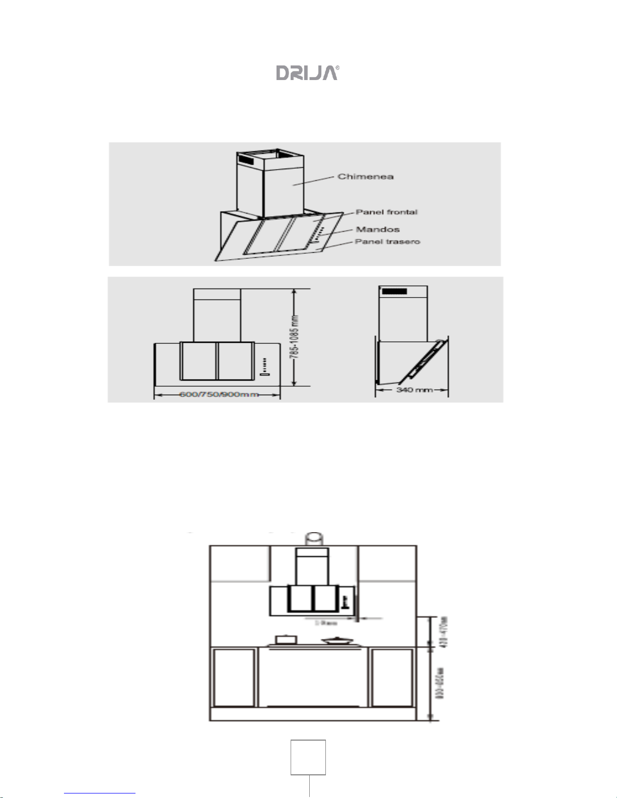
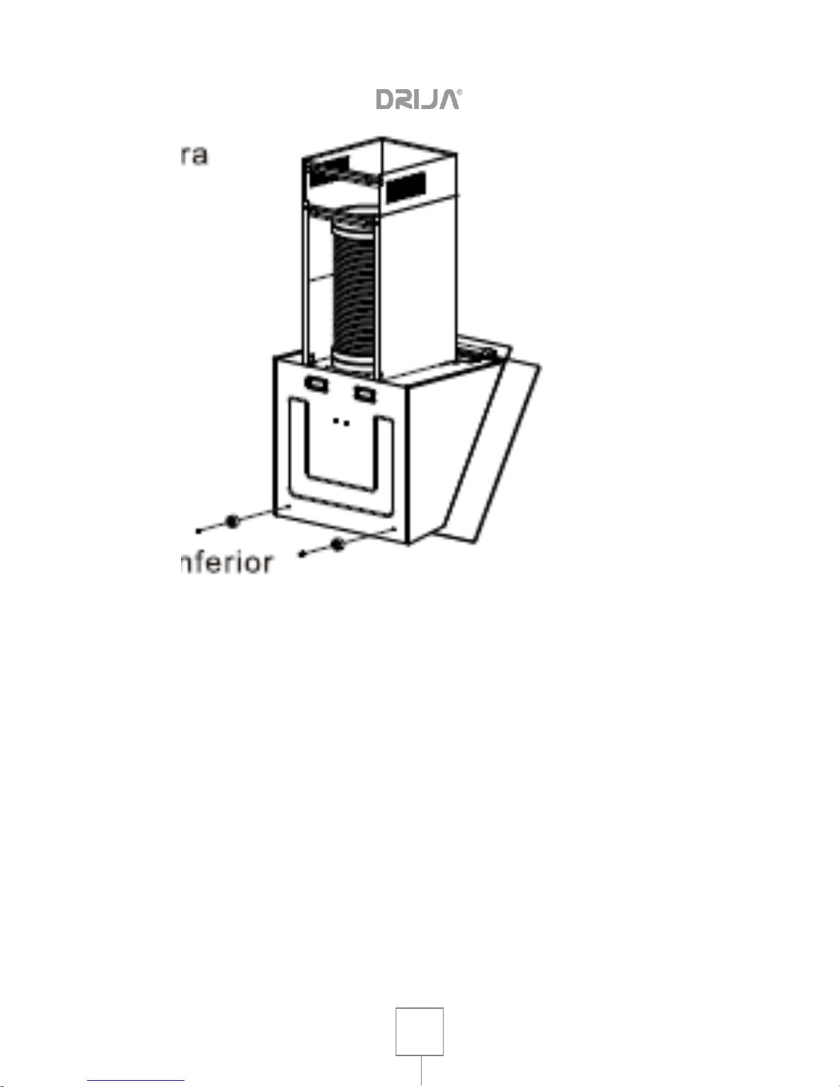
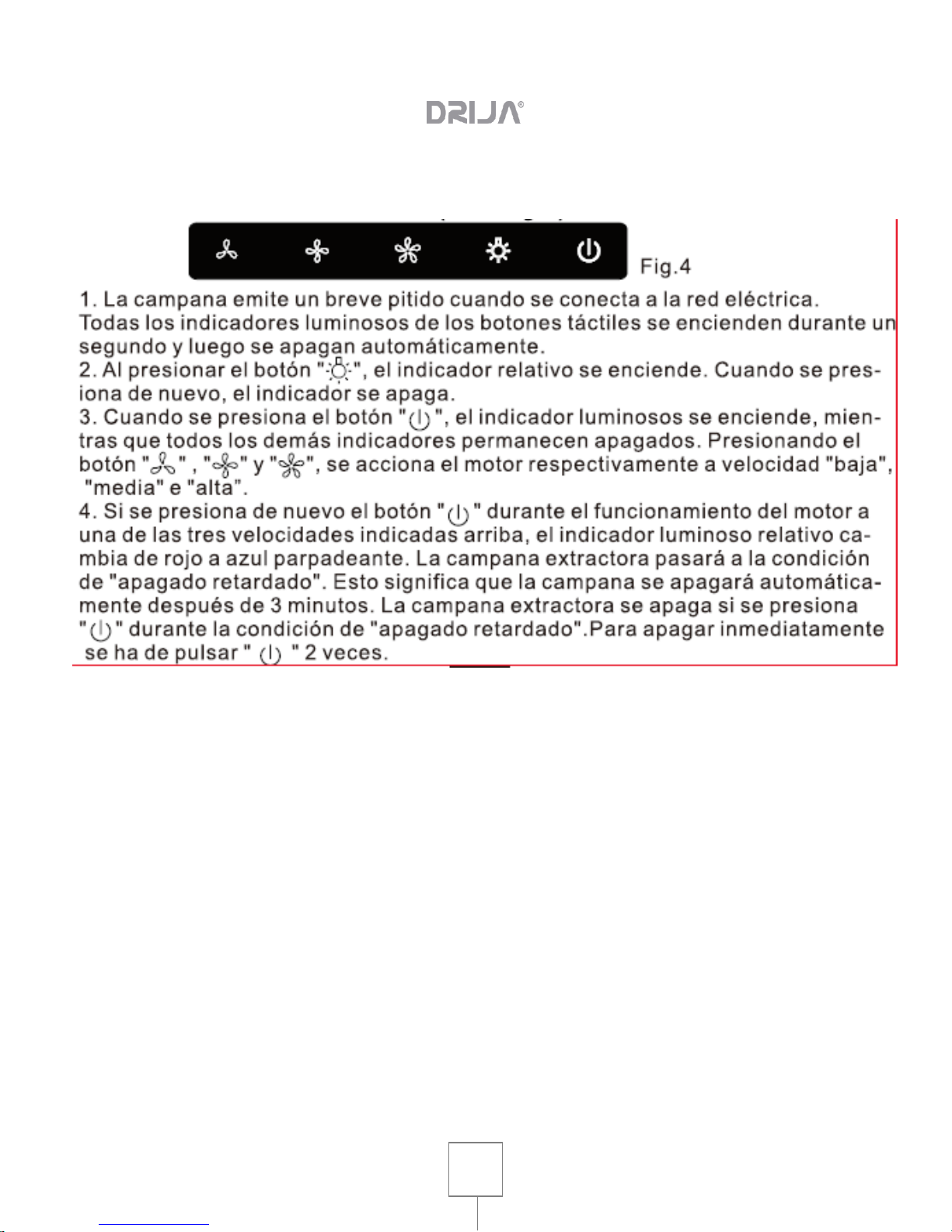
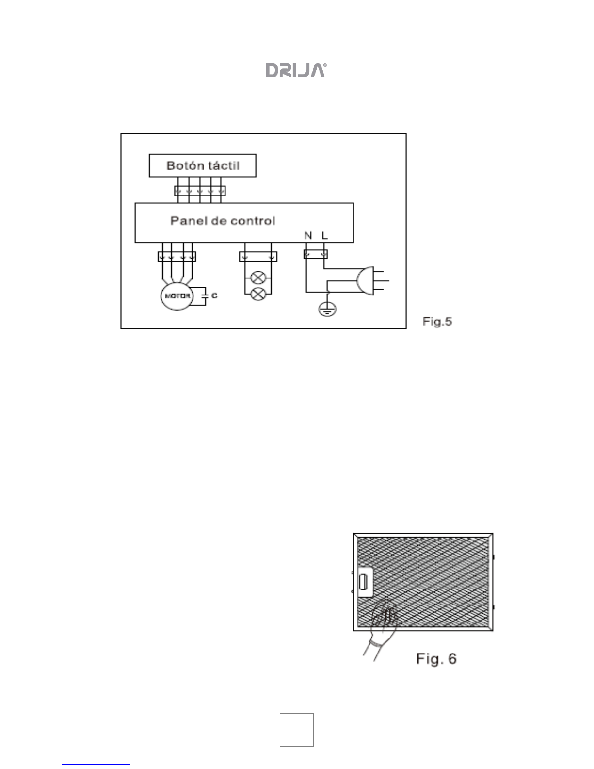
Drija VETRO 75 User manual

User Manual
VETRO 75
Voltage 110V-120V

User Manual
RANGE HOOD | VETRO 75 Professionale
2
1. ADVICE AND SUGGESTIONS ..................................................................... 3
2. SCHEMATIC DESIGN OF THE PRODUCT.................................................. 5
3. INSTALLATION............................................................................................. 5
4. CIRCUIT CONTROLS AND SCHEMES........................................................ 8
5. CIRCUIT DIAGRAM...................................................................................... 9
6. MAINTENANCE ............................................................................................ 9
7. TROUBLESHOOTING ................................................................................ 10
8. WARNINGS................................................................................................. 11

User Manual
RANGE HOOD | VETRO 75 Professionale
3
1. ADVICE AND SUGGESTIONS
Instructions for use apply to various models of this appliance. Therefore you can
find descriptions of individual characteristics that do not belong to your particular
device.
The manufacturer is not liable for damage caused by installation or improper use.
INSTALLATION
• The minimum safety distance between the cooking surface and the extractor is
420mm (some models can be installed at a higher height, see paragraph
concerning working dimensions and installation).
• Check that the supply voltage corresponds to that indicated on the data plate
inside the extractor.
• For Class I appliances, check that the mains supply is properly grounded.
• The smoke path should be as short as possible.
• Do not connect the extractor to smoke ducts carrying combustion smoke (eg
boiler, chimneys, etc.).
• If the extractor is used in combination with non-electric appliances (eg gas
appliances), a sufficient degree of ventilation must be ensured in the enclosure to
prevent the return of the exhaust gas flow. The kitchen should have an opening
communicating directly with the outside to ensure fresh air. When using the kitchen
extractor in combination with appliances not powered by electric current, the
negative pressure in the enclosure should not exceed 0.04 mbar to prevent smoke
from being breathed into the enclosure by the extractor.
• In the event of damage to the power cord, it must be replaced by the
manufacturer or service department to avoid any risk.

User Manual
RANGE HOOD | VETRO 75 Professionale
4
USE
The fat extractor is designed exclusively for domestic use, to eliminate odors from
the kitchen.
• Never use the extractor for purposes other than those for which it was
designed.
• Never leave high flame under the extractor when it is in operation.
• Adjust the flame intensity to direct it to the bottom of the cooking vessel,
making sure that it does not reach the sides.
• Fryers must be continuously checked during use: overheated oil may ignite.
• Do not flambé under the grease remover: a fire may result.
• This appliance is not intended for use by persons (including children) with
reduced psychological, physical or sensory abilities or with insufficient
experience and knowledge, unless supervised and instructed by a person
responsible for their safety.
• Supervise children, making sure they do not play with the appliance.
• WARNING: accessible parts can become very hot during the use of cooking
appliances.
• Turn off or disconnect from the mains before any maintenance or cleaning
operation.
• Clean and / or replace the filters after the specified period of time (fire hazard).
• Clean the extractor with a damp cloth and mild liquid detergent

User Manual
RANGE HOOD | VETRO 75 Professionale
5
2. SCHEMATIC DESIGN OF THE PRODUCT
3. INSTALLATION
• Installation position
The grease extractor should be installed by centering it on the cooking surface.
The reference distance between the extractor and the cooking surface is 420-
470mm (see fig.1 below).

User Manual
RANGE HOOD | VETRO 75 Professionale
6
• Fastening the suspension hook and flange.
Fixing the suspension hook.
Drill into the wall 3 holes of 8mm and depth 50mm and insert into the holes three
expansion plugs. Use 3 ST5x50 screws to attach the suspension hook to the wall
(see fig.2.3 below).
Fastening the flange
Drill into the wall 4 holes (2 holes per flange) of 8mm and depth 50mm and insert
into the holes 4 expansion plugs. Use 4 screws ST5x50 to fix flange A and flange
B. to the wall (see figures 2.1 and 2.2 below).
• Installation of plastic spacer and exhaust duct. Assembly of the body of the fat
extractor.
Use 2 M4x10 screws to attach the plastic spacers to the grease extractor body
(see figure 3).
Mounting the extractor body to the wall.
Use 2 ST4x8 screws to screw the exhaust duct into the exhaust outlet of the
grease extractor.

User Manual
RANGE HOOD | VETRO 75 Professionale
7
• Installation of the chimney
Installation of the lower chimney
Use 2 M4x10 screws to secure the lower chimney to flange B, and then use 2
M4x10 screws to secure the lower chimney to the wall mounted extractor.
Installation of the upper chimney
Use 4 M4x10 screws to attach the top chimney to flange A.
Note: The product must be installed using at least one of the two fireplaces.
For the installation of a single chimney (lower), the flange B must be fixed to the
wall, while the flange fixing A is not required. For the installation of both chimneys
(lower and upper) the flange A must be fastened to the wall, while the flange B
must be fixed to the extractor. However, the attachment of the flange B is optional
for the user.

User Manual
RANGE HOOD | VETRO 75 Professionale
8
4. CIRCUIT CONTROLS AND SCHEMES
Using the electronic controls (see fig.4)

User Manual
RANGE HOOD | VETRO 75 Professionale
9
5. CIRCUIT DIAGRAM
6. MAINTENANCE
To ensure the best performance and durability of the fat extractor,
regular maintenance is required.
Note:
Disconnect the power cord before any maintenance operation and press the "on /
off" button to ensure shutdown.
Wear protective gloves during
maintenance.
Cleaning and replacement of
metal grease filter.
In case of normal use of the grease
remover (1 or 2 hours per day), the
surface of the metal grease should
be cleaned weekly (see fig.6).

User Manual
RANGE HOOD | VETRO 75 Professionale
10
7. TROUBLESHOOTING
IF THE USER CAN NOT SOLVE THE PROBLEMS, YOU SHOULD CONTACT
THE LOCAL REPRESENTATIVE OR THE TECHNICAL OFFICE OF THE
DISTRIBUTOR.
Issue
Cause
Solution
The indicator light is on but
not, but the engine does not
work.
The rotor is clogged.
Remove the cause of the
obstruction.
The capacitor is damaged.
Replace condenser.
The internal motor is stuck
and emits an unpleasant
odor.
The motor bearing is
clogged or damaged.
Replace engine.
The light does not work, the
motor does not work.
In addition to running the
controls mentioned above,
Check if the indicator light is
damaged.
Replace the light.
The power cord is loose.
Connect the wires as shown
in the wiring diagram.
The rotor is damaged and
causes vibrations.
Replace rotor.
The extractor body vibrates.
The motor is not set
properly.
Secure the engine.
The extractor body is not
securely fastened.
Secure the extractor body
securely.
Insufficient aspiration.
There is too much distance
between the extractor body
and the cooking surface.
Correct the distance.
There is too much
ventilation of open doors or
windows.
Choose a new location and
reinstall the device.

User Manual
RANGE HOOD | VETRO 75 Professionale
11
8. WARNINGS
• If the power cord is damaged, it must be replaced by the manufacturer, its
authorized service agent or similarly qualified personnel to avoid any risk.
• Adequate ventilation should be provided in the room where the grease extractor
and other gas and other combustible devices are located (do not use with
appliances having a single air outlet in the room). There is a fire hazard if cleaning
is not performed according to the instructions, do not flambé under the grease
remover.
• WARNING: accessible parts can become very hot during the use of cooking
appliances.
This manual suits for next models
1
Table of contents
Other Drija Ventilation Hood manuals

Drija
Drija PRISMA ISLA TOUCH 90 User manual

Drija
Drija COMPACTA 76 User manual

Drija
Drija PRISMA 76 Professionale User manual

Drija
Drija PRISMA TOUCH 76 User manual

Drija
Drija PRISMA ISLA TOUCH 90 User manual

Drija
Drija Galaxy 76 User manual

Drija
Drija Urano 90 User manual

Drija
Drija Prisma Isla 90 User manual

Drija
Drija Square Isla Professionale Series User manual

Drija
Drija GALAXY 90 User manual