Drive Master Back Up Steering System User manual

Back Up Steering System
2001 - Present
Daimler-Chrysler Mini Vans
Installation Manual and Owner’s Guide
37 Daniel Rd. West, Fairfield, NJ 07004-2521 • 973-808-9709 • FAX 973-808-9713 • E-MAIL: sales@drivemaster.net
Providing Mobility for
the Physically Challenged
Since 1952
DCBUS Rev 03-09
This manual contains 2001-2008
installation instructions.
2001 - 2007 - Front of book
& general information.
2008 - Instructions for 3.8 and 3.3
engines are in the rear of the manual.
STOP

2
Mobility Dealer and Installing Technician
Congratulations,
You have just purchased the finest, most
reliable Back-Up Steering system manu-
factured. We are offering a 3 year/36,000
mile manufacturer’s components warranty
– see warranty pages for details. Please
read and reread these instructions as im-
provements have been made to make your
installation easier and the components last
longer. If you follow the directions step by
step as instructed, you will not encounter
any problems and you will have a proper
installation.
If you have any questions call 973-808-9709 between 8 am and
4:30 pm, Monday through Friday and ask for technical assistance.
Thank you for supporting Drive-Master Products.
Yours in mobility,
President

3
DEALER WARNINGS
1. The back-up system should not be used to take the place of the fac-
tory power steering system.
2. Route all hoses to prevent rupture or chafing of back-up and factory
lines and keep away from hot exhaust & manifold components.
3. Only trained and certified technicians can install Drive-Master back-
up systems, otherwise the warranty will be void.
4. Do not mount back-up steering pump unit with the reservoir ports
facing down towards the ground.
5. Flow sensor fittings and wires were specially checked for security
prior to leaving our factory. Take care when installing not to loosen
or break wires. To do so will DAMAGE FLOW SENSOR AND
INVALIDATE WARRANTY. Refer to troubleshooting guide for test
procedures
6. Do not make any electrical connections that are different than the
Drive-Master wiring instructions.
7. Disassembling components without prior Drive-Master notification
and a valid Return Authorization (RA) in writing by a Drive-Master
office liaison will void warranty, and a charge will be issued for any
replacement parts. DO NOT CUT HARNESS’WHEN REMOVING
ELECTRICAL WIRING FOR RETURN-THIS WILL VOID WAR-
RANTY!
8. 2001 through 2005 Daimler/Chrysler minivan products-Check the
OEM return line from the cooler to the OEM fill reservoir to see if
there is a metal restrictor in the line. This can be seen from under
hood, right side of motor from reservoir. If there, remove and discard
the line. Replace with the yellow push-lok hose supplied. FAIL-
URE TO DO THIS WILL RESULT IN HOSE FAILURE AT
THE COOLER END AND VOID THE WARRANTY!
9. Drive-Master does not have a labor reimbursement program. So, if
you cannot diagnose the problem in 15 minutes, do not waste any
more time and phone for technical assistance. (973) 808-9709 Mon.
- Fri. 8:00AM - 4:30PM EST.

4
Back-Up Steering System Operation
for the owner/user
The Drive-Master Back-Up Steering system is designed to provide emergency power
steering in the event of engine stall or OEM power steering failure. You have a Back-Up
Steering System because your OEM steering is modified to low or no effort. The Drive-
Master back-up steering pump will automatically activate when the OEM power steering
flow is disrupted. Audible and visual alarms alert the driver of the activation of the back-
up steering system. (WARNING: THE ALARM BUZZER WILL STAY ACTIVE AS A
REMINDER TO THE DRIVER TO GET OFF THE ROAD AS SOON AS POSSIBLE.
STOP AND TURN OFF THE VEHICLE AND SUMMON HELP.)
The Drive-Master Back-Up system will become operational after the vehicle is running.
This exclusive feature is accomplished by the Drive-Master back-up module (or relay in
the toggle switch equipped model). Excessive current draw from the battery is eliminat-
ed until the engine is started. The back-up system’s operation can be tested two ways:
1. Start the engine. Turn the steering wheel left or right fully to end stops. The sys-
tem will engage when the wheel hits the stop. The warning buzzer will sound (if
equipped with buzzer), and the LED will light, alerting the driver of the back-up
system’s operation.
2. The test/emergency switch can be manually operated from the Drive-Master back-
up steering control module (or toggle switch) which overrides the system and acti-
vates the back-up steering immediately. Push the button or operate the toggle
switch to the on position - the pump will run. Push the button again or toggle the
switch to off & the pump will turn off.
The flow rate of the back-up steering pump is 3.5 gallons per minute. The system isV.A.
tested and accepted. It will operate beyond the 180 second specification required forV.A.
clients. The back-up system has its own one quart reservoir, and operates on the vehi-
cle’s 12 volt battery.
Maintenance: Maintain normal fluid level in the OEM power steering reservoir. This
should be checked when engine oil and filter are changed, every 3000 to 5000 miles.
Leaks: Any dripping or leak detection under vehicle – return to your mobility equip-
ment dealer for repairs immediately.
Steering: If steering becomes hard to steer or noisy - return to your mobility equipment
dealer for repairs immediately.
Annually, or every 30,000 miles - Return to your mobility equipment dealer for complete
system check and replacement of the OEM Power Steering fluid in the system.
Continuous Operation: if the BUS motor runs continuously, turn vehicle off immedi-
ately and call your dealer for service.

5
DRIVE-MASTER
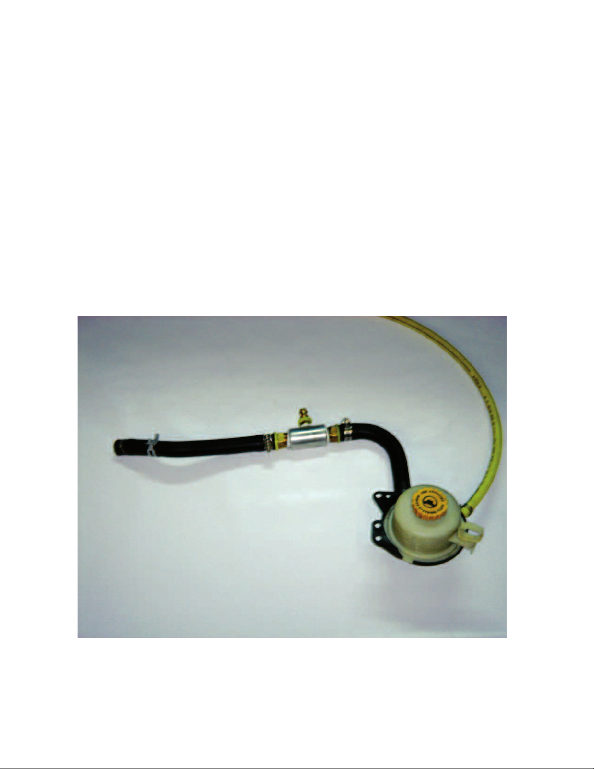
BACK-UP STEERING SYSTEM
LIMITED PARTS ONLY WARRANTY
DRIVE-MASTER warrants that the parts of your new Back-Up Steering System are free from defects in materials or
workmanship for a period of 3 years or 36,000 miles from date of first retail purchase, whichever occurs first.
Return of Warranty Registration Card
Your return of the attached Warranty Registration Card within 10 days of your purchase is a condition of per-
formance under this Limited Parts-Only Warranty.
What This Warranty Gives You:
If your Drive-Master Back-up Steering System is properly operated and maintained, any component covered by this lim-
ited warranty found to be defective in materials or workmanship, will be replaced without charge.
Under this limited warranty, the sole and exclusive remedy is the replacement of defective parts with new or remanufac-
tured parts, within Drive-Master’s sole discretion.
NOTE – the cost of labor to install parts provided under this Limited Parts-Only Warranty is not covered by this
Limited Parts-Only Warranty.
This Is Your Only Written Warranty
This Limited Parts-Only Warranty is the only express warranty applicable to your Back-up Steering System. Drive-Master
does not authorize anyone to modify this Limited Parts-Only Warranty or to assume for Drive-Master any other obligation
or liability in connection with this Limited Parts-Only Warranty.
Limitation on Implied Warranties and Consequential Damages
All Implied Warranties, including the implied warranties of merchantability and fitness for a particular use, are limited,
to the extent allowed by law, to the time period covered by this Drive-Master New Back-up Steering System Limited
Parts-Only Warranty, or to the applicable time period provided by state law, whichever period is shorter.
Drive-Master is not responsible for any time that you lose, for any inconvenience you might be caused, for any commer-
cial loss, for the cost of alternative transportation or hotels, or for any other incidental or consequential damages you may
incur.
Some states do not permit a limitation on how long an Implied Warranty will last, or the exclusion or limitation
of incidental or consequential damages, so the above limitation and exclusion may not apply to you.
This Warranty gives owners specific legal rights, and they may also have other rights that vary from state to state.
What Is Not Covered under this Limited Parts-Only Warranty
– Damage caused by accident or misuse or abuse
– Alteration, tampering or modification of the Back-up Steering System
– Claims involving disconnection or alteration of the vehicle odometer, or where the actual vehicle mileage cannot
otherwise be determined
– Damage caused by failure to maintain or improper maintenance of the Back-up Steering System
See your Owner Maintenance section for proper maintenance of your Back-up Steering System.
We recommend servicing at qualified NMEDA dealers. Make sure your service location fills out the maintenance record
in your owners manual so you will have a means to demonstrate that proper service has been performed.
– Other items and conditions not covered by this limited warranty
–
Non - Drive-Master parts
–
Normal wear and tear
How To Make A Claim
Contact Drive-Master at the following address and telephone:
37 Daniel Rd. West, Fairfield, NJ 07004 - 973-808-9709
Return of defective parts may be a condition of claim approval.
We suggest that you use mobility dealers who are members of the National Mobility Equipment Dealers Association
(NMEDA). See www.nmeda.org or call us at 973-808-9709 and ask for the closest dealer.

6
Parts List
Back-Up Steering Kit
2001 and up Daimler Chrysler Minivans
1 Back-Up Steering pump and motor assembly
1 Back-Up Steering solenoid
1 24" 2 Gauge Red with lugs - used between solenoid and the battery
1 48" 2 Gauge Red with lugs - used between solenoid and the back-up Steering pump
1 65" 2 Gauge Black with lugs - used between pump bracket and negative battery terminal
1 12" 4 Gauge Black with lugs - used between the battery negative and body ground point
(ground strap)
1 25" High Pressure Hose with BLUE marking - compression side for OEM power steering
1 33" High pressure Hose – used between back-up Steering pump and shuttle-flow sensor
assembly
1 54" High Pressure Hose with RED marking - compression side for rack high pressure
1 66-1/2" PUSH-LOK Hose - used between T assembly and the back-up Steering low pres-
sure canister
1 24" x 3/8" PUSH-LOK Hose – used between the OEM reservoir and low pressure cooler line
1 T Assembly 3/4"x1/2"x3/4"
1 Shuttle valve-flow sensor assembly - Flow sensor marked BLUE. Shuttle valve marked RED
1 2 Piece Shuttle valve-Flow sensor assembly bracket with 1/4" – 20 x 1-3/4" bolts and 1/4" x
20 lock nuts
1 1/4" x 20 x 1-1/4" bolt with lock nut – used for hood prop bracket
2 1/4" x 3/4" hex head self-tapping screws – used for mounting solenoid
1 Back-Up Steering Control module with wiring harness
2 #6 hose clamps
2 #12 hose clamps
>For Daimler Chrysler service bulletin 19-004-03 if necessary
1 33-1/2" Yellow PUSH-LOK hose
2 #6 hose clamps
1 Warning Label
1 Warranty Registration Mailing Card
1 Consumer User/Warranty Book

7
1. Open hood for access to engine compartment.
2. Disconnect the OEM battery.
3. Remove both headlights.
4. Remove the front bumper clip.
5. Remove the wiper arms. (2001 - 2007 only)
6. Remove the wiper cowl. (2001 - 2007 only)
7. Disconnect the wiper fluid tube and the wiper power plug, then remove the lower wiper
cowl assembly. (2001 - 2007 only)
8. Cut the OEM high pressure line as shown. This cut should be made with a tubing cutter
and should not be cut where the lines bend.
9. Drain the OEM power steering fluid while you work on the rest of the install.
High Pressure Cut
Cut line
shown, high
pressure line
to rack

8
10. Locate the center point on the top of the front bumper and mark it.
This will be the center point for the back-up steering pump bracket.
11. Make sure to protect the radiator while drilling and bolting the back-
up steering pump. A 1/4" spacer can be used to space the back-up
steering pump away from the radiator while installing.
12. Bolt on the back-up steering pump. Use the 5/16 hole in pump hous-
ing marked GRD to connect the 48” #2 black ground cable. The other
end is to be connected to the negative terminal on battery. Failure to
do so can cause poor or no operation of pump and damage to the
vehicle & causes High Pressure hose to short out & seperate (See
inset below).
13. Remove plug in reservoir and using a funnel, fill with new clean
OEM Power Steering Fluid. Reinstall plug.
Low and high pressure installed on B.U.S. pump

9
14. Remove the OEM low pressure hose located between the OEM
power steering reservoir and the OEM low pressure line going to the
power steering cooler.
15. Install the provided 3/8" PUSH-LOK hose between the OEM reser-
voir and the OEM low pressure cooler line. #6 Hose clamps should
be used to secure the PUSH-LOK hose.
Remove OEM low pressure line

10
16. The T assembly can now be installed as shown in this picture. (Also
see step #18.) This picture is to demonstrate location of the T assem-
bly. Cut 3" out of the OEM fill line and insert the T assembly with
the 1/2" barbed fitting facing slightly downward.
17. Use the #12 hose clamps to secure the T assembly.
T inserted into OEM low pressure fill line

11
18. Attach the 1/2" gray PUSH-LOK hose to the T fitting. IMPOR-
TANT!!!! This 1/2" PUSH-LOK line must slope downward toward
the back-up steering pump. This must be a continuous straight slope,
no rises as it will trap air in the system.
T insert with push lok hose
Slope downward
towards bus pump

12
19. Attach the remaining side of the 1/2" PUSH-LOK hose to the back-
up steering pump’s 1/2" barbed fitting.
20. Install the 33" high pressure hose using Teflon tape. Install one end
into the high pressure output side of the back-up steering pump.
Back-up Steering Pump with hoses

13
Shuttle-flow Valve Assembly
Shuttle valve and flow sensor assembly

14
21. Insert the remaining end of the high pressure line from the back-up
steering pump into the shuttle valve-flow sensor input fitting.
High pressure line attached to shuttle-flow assembly

15
22. Locate the OEM high pressure line from the OEM power steering
pump. Remove the retaining clamp located on the back side of the
engine block. This 13 mm bolt can be removed from under the vehi-
cle with extensions and a swivel socket.
23. Using a 16mm LINE WRENCH remove the OEM high pressure line
from the back of the OEM power steering pump. Use caution not to
damage the o-ring located on the end of the OEM high pressure line.
24. Cut the OEM high pressure line in the middle of the center bend as
shown in picture below. Clean and deburr the cut line. Use solvent
wash to clean the inside of the high pressure line then blow out with
air.
OEM high pressure line cut

16
25. Clean the end of the cut. Bend the OEM line into more of a U-shape.
Use EXTREME CAUTION not to kink the line.
26. Place the line in a vice and slightly twist the line so it will lay flat on
the bench.
OEM high pressure line bend

17
27. Locate the 25" BLUE High pressure hose and attach the compression
side to the OEM high pressure line.
28. Make sure the O-ring is still present and reinstall the modified OEM
high pressure line with the line facing upward and toward the front of
the vehicle.
OEM high pressure line removed

18
29. Locate the 54" RED High pressure line and attach the compression
side to the input line going to the rack.
View from under vehicle
High pressure line to rack

19
30. Apply Teflon tape on the RED marked high pressure line and install
into the shuttle valve marked with RED.
31. Apply Teflon tape on the BLUE marked pressure line and install into
the flow sensor.
High pressure line installed

20
32. Add the ground strap from the negative battery terminal to a cleaned
ground point.
33. Mount the back-up steering solenoid as shown, utilizing the OEM
hole in the cross member and the screws provided.
Attach ground strap
Table of contents
Popular Automobile Accessories manuals by other brands

Cruz
Cruz Evo Rack Alu A23-126 Assembly instructions

Subaru
Subaru F411SXC020 installation instructions

Whispbar
Whispbar K304W Fitting instructions

Canyon
Canyon MagSafe CM-15 quick guide

STO N SHO
STO N SHO SNS 130 Installation procedures

Voxx Accessories
Voxx Accessories DIRECTWIRE DIRECTECHS DS3 installation guide