3. VEILIGHEID
3.1 ALGEMEEN
- Leest u dit hoofdstuk over veiligheid
zorgvuldig door voordat u begint met
installatie of onderhoud;
- Houdt u zich aan de algemeen
geldende voorschriften en de
voorzorgsmaatregelen/veiligheids-
instructies in deze handleiding.
3.2 VOORSCHRIFTEN
Installeer het toestel volgens de geldende Europese, nationale,
lokale en bouwkundige (installatie)voorschriften.
Voor Nederland geldt onder meer het Bouwbesluit.
3.3 VOORZORGSMAATREGELEN / VEILIGHEIDS-
INSTRUCTIES BIJ INSTALLATIE
Volg de onderstaande voorzorgsmaatregelen/
veiligheidsvoorschriften nauwkeurig op:
● installeer en onderhoud de haard alleen als u een
vakbekwame installateur op het gebied van houtgestookte
toestellen bent;
● plaats de haard op een vloer met voldoende draagkracht;
● plaats de haard en/of de kachelpijpen voor een wand van
niet brandbaar materiaal;
● breng indien u brandbare materialen aantreft voldoende niet
brandbaar isolatie materiaal aan;
● plaats de haard en/of de kachelpijpen op minimaal 50 mm
vanaf de niet brandbare wand;
● plaats de haard en/of de kachelpijpen altijd op minimaal
700 mm afstand van brandbare objecten en/of materialen;
Bij het model Kalle is deze minimale afstand 800 mm.
● plaats de haard op een beschermende vloerplaat in geval
van een brandbare vloer. De vloerplaat van niet brandbaar
materiaal dient minimaal 300 mm voor de haard uit te steken
en een minimaal 300mm breder te zijn als de haard;
● dek de haard niet af en/of pak deze niet in met een
isolatiedeken of enig ander materiaal;
● sluit de haard aan op een geschikt rookgaskanaal;
● laat het rookgaskanaal vooraf inspecteren en reinigen door
een erkend schoorsteenveegbedrijf;
● breng zelf geen wijzigingen aan de haard aan;
● gebruik uitsluitend originele onderdelen ter vervanging;
● zorg voor voldoende ventilatie in de opstellingsruimte.
4 UITPAKKEN
Schenk aandacht aan de onderstaande punten bij het uitpakken
van de haard:
● controleer het toestel op transportschade, plaats nooit een
beschadigde haard;
● controleer of de doos met onderdelen compleet is.
In Bijlage 1 / Tabel 1 staat vermeld over welke onderdelen
u na het uitpakken dient te beschikken;
● door het transport kunnen onderdelen verschoven zijn,
controleer de liggen van de keerplaat en vermiculietplaten.
● controleer de werking van luchtschuif, deursluiting en het
eventuele draaimechanisme;
● verwijder eventueel achtergebleven straalgrit uit de
luchtschuif;
● neem zonodig contact op met uw leverancier;
● voer de verpakking af via de reguliere weg.
5. INSTALLATIE
5.1 VOORSCHRIFTEN
● Installeer de haard volgens de geldende Europese,
nationale, lokale en bouwkundige (installatie)voorschriften.
● Houdt u zich aan de voorschriften/instructies zoals vermeld
in deze handleiding.
5.2 ROOKGASKANAAL
Voor het rookgaskanaal gelden de volgende eisen:
− het rookgaskanaal moet van tevoren geïnspecteerd worden
door een specialist;
− het rookgaskanaal dient geschikt te zijn voor aansluiting van
een houtgestookt toestel;
− de haard dient te worden aangesloten op een enkel,
ongedeeld rookgaskanaal;
− het rookgaskanaal moet schoon zijn;
− het rookgaskanaal moet gasdicht zijn;
− de versleping in het rookgaskanaal mag maximaal 1,5 meter
bedragen met een minimale hoek van 45 graden vanuit het
horizontale vlak;
− bij achteraansluiting op de haard mag het horizontale deel
van het rookgaskanaal maximaal 500 mm bedragen;
− bij gebruik van de achteraansluiting van de haard op een
verticaal rookgaskanaal moet een T-stuk met roetzak worden
toegepast;
− de diameter van het rookgaskanaal moet minimaal gelijk zijn
aan de diameter van de rookgasafvoer van de haard;
− de trek van het rookgaskanaal moet minimaal 12 Pascal zijn;
− in een (te) sterk trekkend kanaal dient zonodig een
rookgasklep worden aangebracht;
− kachelpijpen moeten afwaterend naar de haard worden
geplaatst;
− het rookgaskanaal dient zelfdragend te zijn en mag niet op
de haard rusten;
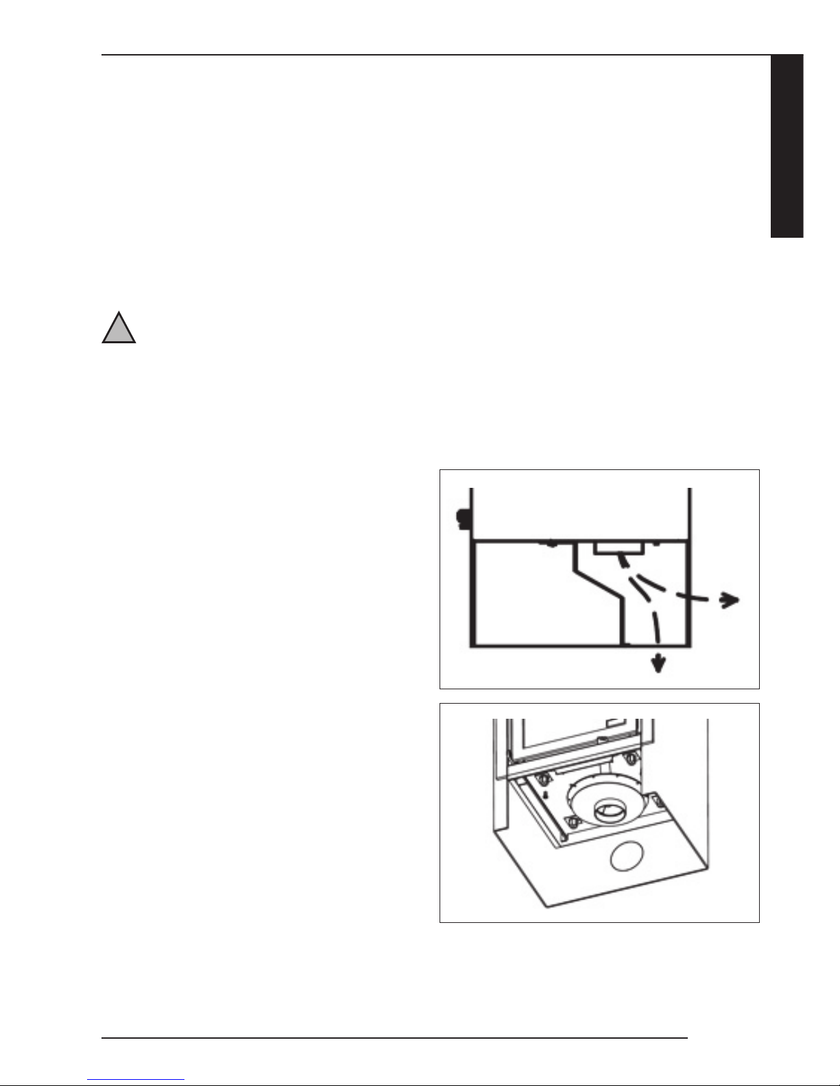
5.3 OMBOUWEN BOVENAANSLUITING NAAR
ACHTERAANSLUITING HAARD
De haard wordt geleverd met een bovenaansluiting voor het
rookgaskanaal. De bovenaansluiting kan indien van toepassing
omgebouwd worden naar een achteraansluiting (zie foto).
Volg hiervoor de onderstaande stappen:
6
!Let op