manuals.online logo
Brands
  1. Home
  2. •
  3. Brands
  4. •
  5. Dryflow
  6. •
  7. Dryer
  8. •
  9. Dryflow DF35DM Service manual

Dryflow DF35DM Service manual

INTELLIGENT FACILITY SOLUTIONS
Electric Works, 3 Concourse Way, Sheffield, S1 2BJ
United Kingdom Phone UK: +44 (0) 114 354 0047
Phone Eire: +353 190 36387
sales@ihdryers.co.uk
www.intelligenthanddryers.com
Model :
Deck-Mounted
DF35DM
Dryflow® Dri-Tap
Hand Dryer
Operating Instructions and Parts Manual (Automatic)
1
ITEM CATEGORY
Operating Voltage
Motor Type
Motor Thermal Protection
Heater Element
Heater Thermal Protection
Drying Time
Stand-by Power
Circuit Operation
Sensor Range
Timing Protection
Drip proof
Isolation
Net Weight
Shipping Weight
Type
Dryer Body Cover Type
Spout Size
Dryer Body Size
Warm Air Speed Output
Air Output Temperature
Dryer Shall Deliver
Spout
PERFORMANCE DATA
TECHNICAL SPECIFICATIONS
110-120 Vac, 50/60 Hz, 7.6-8.4 A, 0.84-1.0 kW
84-
220-240 Vac, 50/60 Hz, 3.8-4.2 A, 0.84-1.0 kW
500 W, 22,000-29,000 R.P.M. , Brush Type, Dual Ball Bearings
Auto Resetting Thermostat turns unit off at 95 °C [203 °F]
100-500 W, depending on room temperature
Thermal cut-off at 85 °C [185 °F]
Less than 15 seconds
0.3-0.4 W
Infrared Automatic, self adjusting
4" to 9" [100 mm to 230 mm], Adjustable; standard 5.12" [130 mm ± 20 mm]
60 seconds auto shut off
IP35
CLASS 1
5.6 kg [12.3 lbs]
8.1 kg [17.9 lbs]
Stainless steel (#304), Satin finished ( t:3.0 mm & 1.5 mm )
Stainless steel (#304), Satin finished ( t:1.2 mm)
50 mm (W) x 170 mm (H) x 220 mm (D)
[1.97" (W) x 6.69" (H) x 8.66" (D)]
306 mm (W) x 193 mm (H) x 148.5 mm (D)
[12.05" (W) x 7.6" (H) x 5.85" (D)]
101 m/s [187.9-225.9 mi/h]
57 °C [122 °F] – Ambient Temp. 25 °C [77 °F]
54 m³/h, (32 CFM)
273
(10.75)
193
(7.6)
Unit Size: mm (Inch)
220
(8.66)
Ø38
Ø50
15
170
(6.69)
306
(12.05)
148.5
(5.85)
34.5
(1.36)
Ver.A2
Spout Cover
Disconnect power at
the service breaker before installing or
servicing. NOT FOR HOUSEHOLD USE -
MAY CAUSE BURNS.
All units must be
supplied with a 3-wire service. The
ground wire must be connected to the
dryer's backplate.
Failure to properly
ground unit could result in severe
electrical shock and/or death.
2
Circuit Diagram
Circuit Board Module
Transistor
Power Switch
MO2 HE2 NMO1 HE1L
Transistor
Power Switch
VR
Thermostat
Red( 110 -1 20V)/Br ow n (208- 24 0~277 V)
Black
Black
G/Y
Blue
Brown
Motor With Ther mal Switch 2A
Heater With Thermo-fuse
FOR SENSOR
SW.F OR HEATER
Whit e( 110 -120V)/ Bl ue (208 -2 40~27 7V )
Sensor module
ON
1
VR FOR SPEED
G
G/Y Y2 Filter
(ONLY 208~240V)
(ONLY 208~240V)
L
N
G
For Temperature Control
【Type Y attachment】
If the power supply cord is damaged, it must be replaced by the manufacturer
or its service agent or a qualified person in order to avoid a hazard. Disconnect
the fixed wiring only in accordance with the wiring rules.
This appliance is not intended for use by persons (including children) with
reduced physical, sensory or mental capabilities, or lack of experience and
knowledge, unless they have been given supervision or instruction concerning
use of the appliance by a person responsible for their safety.
Children should be supervised to ensure that they do not play with the appliance.
This product is
intended for installation by a qualified
service person. Use2.08 mm² solid
conductor for wiring.
(AWG NO.14)
General Safety Information
Installation
3
1.Drill a hole (size:35mm/ 1.37") on the basin.
Installation location to be decided by the
site owner.
2.The center of the mounting hole to the
edge of the basin and to the edge of the
wall (1.18-1.57 )should be at least 30-40mm " .
Otherwise the mounting nut would not fit.
35mm
(1.37 )"
3. Mounting steps of the spout:
A. Insert the shaft of the spout through the
hole on the basin.
B. Thread in the rubber pad, the stainless
steel washer, and the plastic mounting nut.
C. Fasten with the hex tool.
A
Center point
Mounting hole
Recommended Deck Thickness:10-30mm(0.39-1.18 )"
4.Remove two screws from the cover.
A≧30-40mm
"(1.18-1.57 )
A
Washer
Pad
Nut
4
Installation
7.Insert the wire set and the g
through the flexible tube.
rounding wire
8.Remove the packing from the connector.
Insert the wire set and the rounding wire
through the air nozzle.
Fasten the flexible tube to the air nozzle.
Fasten the other end of the flexible tube
to the shaft of the spout.
g
5.Fix the stainless steel cabinet to the wall,
lead the power cord through the KO hole
and connect it to the dryer.
POWER CORD
6.Connect the wires to the terminal as below:
Connections:
A. Connect the live wire (colored red or brown or white)
to the terminal block marked "L".
B. Connect the neutral wire (colored black or blue)
to the terminal block marked "N".
C. Connect the ground wire (colored green and yellow)
to the green screw marked " ".
air nozzle
packing
Installation
12.Fasten two screws on the cover.
5
11.Connect the grounding wire.
9.Encase the packing onto the wire set and
the grounding wire.
Reposition the packing to the connector.
10.Connect the
and the LED wire) to the CBM.
wire set (including the
sensor wire
7
Installation Height
Suggested installation:
30-32cm under the basin
(depending on the site)
Basin
Flexible tube
Center line
Cover
The acceptable deviation from the center line
is ±2cm. If it has to be deviated for more than
±2cm due to the restriciton on site. Please ensure
the flexible tube would not detach or bend.
A detached or bent flexible tube may result in
Abnormal air volume or air speed.
Remark:
6
13.Install the dryer body under the counter.
Installation
Recommended Deck Thickness:10-30mm(0.39-1.18 )"
7
Operation
No-touch operation.
Shake excess water from hands.
Place hands under the outlet to start operation.
Rub hands lightly and rapidly.
Stops automatically after hands are removed.
Periodic cleaning of the unit is recommended to ensure optimal performance.
Cleaning and Maintenance
Disconnect the electrical supply.
Remove the two cover-mounting screws.
Remove the cover from the dryer body.
Clean the inside of the dryer and remove any
Replace the cover. Do not over tighten the screws.
Wipe the cover with a damp cloth and mild
cleaning solution. Do not Soak. Never use
abrasives to clean the cover.
Do not flush with water.
Heater Element Switch ON/ OFF
Warm Air Speed Adjustment
SW.FOR HEATER
VR.FOR AIR SPEED
Sensor Range Adjustment
VR.FOR SENSOR
1.Switch off the power, remove the cover screws and
the cover.
2.Use a small Philips head screwdriver or a plastic flat blade
probe to turn the VR shaft. Clockwise [CW] to increase
power to maximum (+) , [CCW] to reduce power
as needed(-) .
1.Switch off the power, remove the cover screws and
the cover.
2.Adjust the heater switch on the CBM with a small
plastic or wooden flat blade probe.
2-1. Slide the switch to "ON" : heater on.
2-2. Slide the switch to "1" : heater off.
2.Clockwise: Increases the sensing range(+) .
3.Counterclockwise: Decreases the sensing range(-) .
4.DO NOT OVERTURN!
1.The range is 4" to 9" [100 mm to 230 mm],
standard setting is 5.12" [130 mm ± 20 mm ]
dust or lint.
8
Diagnostics and Remedies
If the dryer will not run
The dryer cycles by itself
or runs constantly
The dryer runs but air
stream is of low pressure
and/or low velocity
Ensure that there is no obstruction on or in front of the IR sensor. Clean
any dirt or debris off the sensor lens. If the problem persists, contact the
distributor for assistance.
First ensure that the breaker supplying the dryer is operational. If it is,
disconnect the power and remove the dryer cover. Take suitable
precautions to avoid shock hazard. Reconnect the power and check for
voltage at the terminal block. Verify that connections are made correctly.
Ensure that the supply voltage is correct. Dryer will run weakly if the
input voltage is too low. Verify voltage requirement on the unit rating label
and the correct power supply as required.
The dryer makes a loud
noise and does not run
for a complete cycle
Ensure that the supply voltage is correct. Dryer will make a loud
humming noise if the input voltage is too high. Verify voltage requirement
on the unit rating label and the correct power supply as required.
If the problem persists, contact the distributor for assistance.
Symptoms Corrective Actions for Initial Installation Failures
Symptoms Corrective Actions for In-Service Failures
If the dryer will not run
The IR sensor only sees
close range objects
" "
The dryer only blows cold
air during a full cycle
First ensure that the breaker supplying the dryer is operational. If it is,
disconnect the power and remove the dryer cover. Replace the CBM
and the IR sensor module. Take suitable precautions to avoid shock
hazard. Reconnect the power and check for voltage at the terminal block.
Disconnect the power. Remove the dryer cover and disassemble the
blower-motor/fan housing. Test the thermostat for open circuit. Check
the heater element for signs of burning or breakage. Damaged element
must be replaced.
The heater gets hot but
no air stream is produced
or the air stream is of low
pressure and velocity
Disconnect the power. Remove the dryer cover and disassemble the blower-
motor/fan housing. Replace the fan motor.
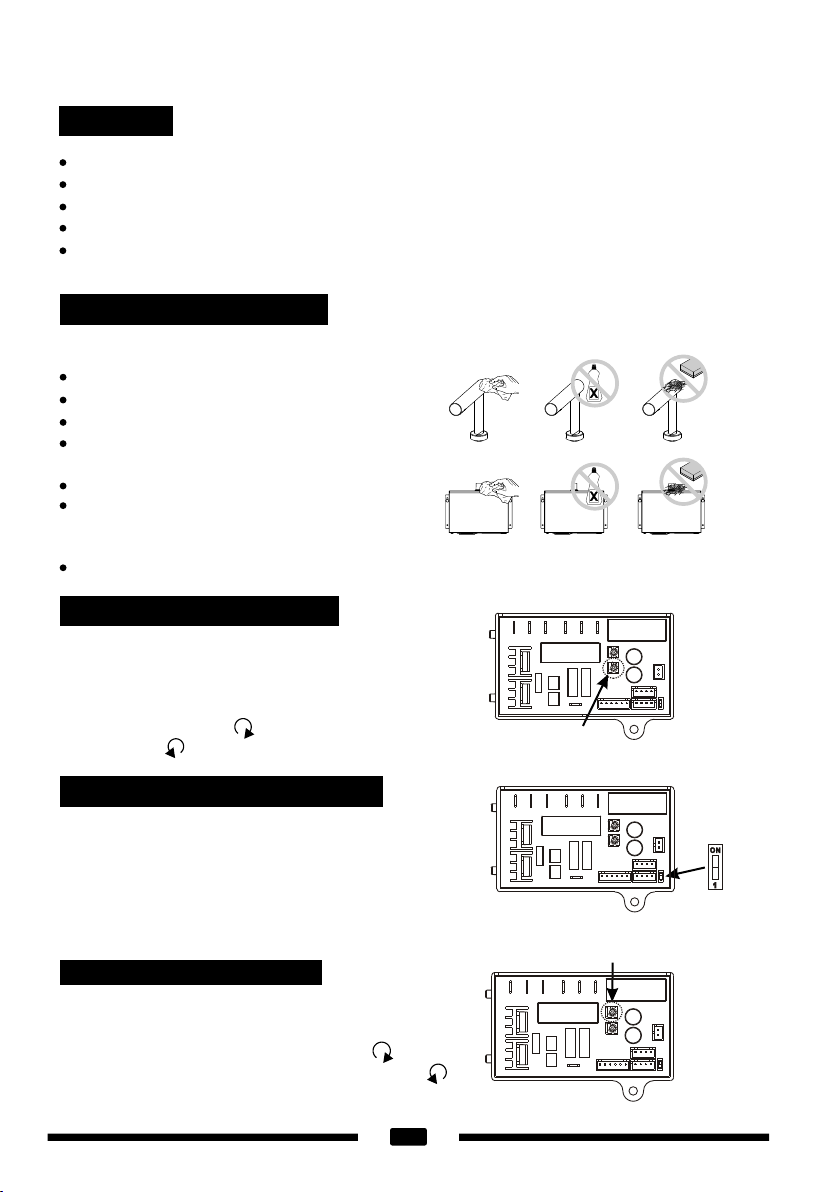
1.Ensure that there is no obstruction on or in front of the IR sensor. Clean
any dirt of debris off the sensor lens.
2.Remove objects under the sensor if any. Disconnect power and
reconnect it to reset the auto-detecting sensing range.
3.Check the VR for the sensing range setting.
4.If the problem persists, contact the distributor for assistance.
LED light indication is not
working
Check if the LED light cable is connected with the circuit board of the
dryer body under the counter.
LED light indication is not
working
Check if the unit works. If it works, replace the LED PCB.
LED light indication is not
working and no air come
out from the dryer.
Change the circuit board of the dryer body under the counter.
4
6
7
8
5
Diagram
9
15
16
17
18
19
20
32
34
21
22
23
24
25
26
27
28
29
30 42
41
40
39
38
37
36
35
10
11
12
13
14
9
Parts inside of spout
31
3
2
1
33
Repair Parts List
10
01
02
03
04
05
06
07
08
09
10
11
12
13
14
15
16
17
18
19
20
21
22
23
24
25
26
27
28
29
30
31
32
33
34
35
36
37
38
Key
Name plate (back)
Air outlet mounting set (upper)
Sensor
Air outlet
Air outlet rubber
Light leading pad
LED light panel
Name plate (Front)
Spout
Air outlet shaft
Tap pad
Pad
Washer
Air outlet shaft screw nut
Flexible tube (30cm)
Stainless Steel Hose Clamp (2 reqd.)
Stainless steel cabinet
Top cap of connector
Packing of connector
Bottom cap of connector
Circuit Board Module
Blower mounting bracket
Blower housing (Below)
Motor rubber (Below)
Motor
Heater assembly
Motor rubber (Upper)
Blower housing (Upper)
Cover
Security hex screw (2 reqd.)
Filter assembly
Packing for wire assembly of sensor & grounding wire
Sensor wire
Nylon hole bushing
Base plate
Grounding Screw
Insulation Mylar
Cable clamp
Grounding wire
Description
39
Cable clamp - EU
40 Terminal block
41 Cable Protector
42 L KEY
Important Information
This Product falls within the scope of the Waste Electrical &
Electronic Equipment Directive 2012/19/EU. (WEEE)
NOTE:
This Product should not be disposed
of with household waste
Please recycle where facilities exist.
Check with your local authority for
recycling advice.

Other Dryflow Dryer manuals

Dryflow 2470IFS User manual

Dryflow

Dryflow 2470IFS User manual

Dryflow BulletDri User manual

Dryflow

Dryflow BulletDri User manual

Dryflow Slimforce User manual

Dryflow

Dryflow Slimforce User manual

Dryflow EcoForce User manual

Dryflow

Dryflow EcoForce User manual

Dryflow MarineDry User manual

Dryflow

Dryflow MarineDry User manual

Dryflow JetForce Pro User manual

Dryflow

Dryflow JetForce Pro User manual

Dryflow JJ02 User manual

Dryflow

Dryflow JJ02 User manual

Dryflow Jet Force Junior User manual

Dryflow

Dryflow Jet Force Junior User manual

Popular Dryer manuals by other brands

Devair DRD 750 instruction manual

Devair

Devair DRD 750 instruction manual

Beko DC8M user manual

Beko

Beko DC8M user manual

Hotpoint TCUD 97B Instruction booklet

Hotpoint

Hotpoint TCUD 97B Instruction booklet

Fisher & Paykel DE4060M Installation instructions and user guide

Fisher & Paykel

Fisher & Paykel DE4060M Installation instructions and user guide

Asko TD75.13 Series Instructions for use

Asko

Asko TD75.13 Series Instructions for use

Samsung DVG45R6300 Series user manual

Samsung

Samsung DVG45R6300 Series user manual

Asko T754C Mode d'emploi

Asko

Asko T754C Mode d'emploi

TJ.Dryingtech TJ-SM801E manual

TJ.Dryingtech

TJ.Dryingtech TJ-SM801E manual

Tricity Bendix TM 221 W Operating & installation instructions

Tricity Bendix

Tricity Bendix TM 221 W Operating & installation instructions

Bosch WTH8520SSN Installation and operating instructions

Bosch

Bosch WTH8520SSN Installation and operating instructions

Beko DU 8112 PA0 user manual

Beko

Beko DU 8112 PA0 user manual

Electrolux EDC804Q5WB user manual

Electrolux

Electrolux EDC804Q5WB user manual

IPSO DR50 owner's manual

IPSO

IPSO DR50 owner's manual

Beko DRX732W user manual

Beko

Beko DRX732W user manual

Frigidaire AGQ6700FE - 27" Gas Dryer Factory parts catalog

Frigidaire

Frigidaire AGQ6700FE - 27" Gas Dryer Factory parts catalog

Bosch WTW87MH0TC User manual and installation instructions

Bosch

Bosch WTW87MH0TC User manual and installation instructions

Zanussi ZDC8203WZ user manual

Zanussi

Zanussi ZDC8203WZ user manual

Grundig GTN 48261 GC user manual

Grundig

Grundig GTN 48261 GC user manual

manuals.online logo
manuals.online logoBrands
  • About & Mission
  • Contact us
  • Privacy Policy
  • Terms and Conditions

Copyright 2025 Manuals.Online. All Rights Reserved.