Devair DRD 750 User manual

Contents
GENERAL SAFETY INFORMATION ............................... 2
RECEIVING, MOVING, UNPACKING ............................. 2
1.0 INSTALLATION ...................................................... 3
2.0 OPERATION .......................................................... 5
3.0 MAINTENANCE .................................................... 6
SIZING ......................................................................... 6
ENGINEERING DATA.................................................... 7
ELECTRICAL SCHEMATICS ........................................... 8
DIMENSIONS / WEIGHTS ............................................. 9
TROUBLESHOOTING .................................................... 10
PARTS LIST .................................................................. 11
WARRANTY................................................................. 12
SERVICE DEPARTMENT: (724) 746-1100
7610.530.11A
9/01
Refrigerated Compressed Air Dryers
Models DRD 200, 250, 300, 400, 500, 750
Instruction Manual
c
For Sales & Service Call: 705-722-5747 Ext.1

1. PRESSURIZED DEVICES:
This equipment is a pressure
containing device.
• Do not exceed maximum operating pressure as
shown on equipment serial number tag.
• Make sure equipment is depressurized before
working on or disassembling it for service.
GENERAL SAFETY INFORMATION
2
2. ELECTRICAL:
This equipment requires electricity
to operate.
• Install equipment in compliance
with all applicable electrical codes.
• Standard equipment is supplied with electrical
enclosures not intended for installation in
hazardous environments.
• Disconnect power supply to equipment when
performing any electrical service work.
RECEIVING, MOVING, AND
UNPACKING
A. RECEIVING
This shipment has been thoroughly checked, packed
and inspected before leaving our plant. It was received
in good condition by the carrier and was so
acknowledged.
Check for Visible Loss or Damage. If this shipment
shows evidence of loss or damage at time of delivery
to you, insist that a notation of this loss or damage be
made on the delivery receipt by the carrier’s agent.
B. UNPACKING
Check for Concealed Loss or Damage. When a shipment
has been delivered to you in apparent good order, but
concealed damage is found upon unpacking, notify the
carrier immediately and insist on his agent inspecting
the shipment. Concealed damage claims are not our
responsibility as our terms are F.O.B. point of shipment.
C. MOVING
In moving or transporting dryer, do not tip dryer onto
its side.
D. STORAGE
IMPORTANT: Do not store dryer in temperatures above
130°F, 54.4°C.
3. BREATHING AIR:
Air treated by this equipment may not
be suitable for breathing without
further purification.
• Refer to applicable standards and specifications for
the requirements for breathing quality air.
For Sales & Service Call: 705-722-5747 Ext.1

3
33°F..............39°F
1°C.............. 4°C
IMPORTANT: READ PRIOR TO STARTING THIS EQUIPMENT
1.0 INSTALLATION
1.1 Location
A. For typical placement in a compressed air system,
see drawing.
B. Air compressor intake–Locate air compressor so that
contaminants potentially harmful to the dryer
(e.g. ammonia) are not drawn into the air system.
C. Clearances Free air flow
Models 200, 300
Front 24 inches (610 mm)
Back 12 inches (305 mm)
Sides 24 inches (610 mm)
Models 400 to 750
Front 12 inches (305 mm)
Back 12 inches (305 mm)
Sides 36 inches (915 mm)
Service - To facilitate maintenance leave 24 inches
(610 mm) of clearance in front of dryer.
D. Standard units are designed to operate in ambients:
Air-cooled: 45 to 110°F (7 to 43°C).
Water-cooled: 45 to 130°F (7 to 54°C).
E. Installations in altitudes above 4500 feet (1370
meters) – Dryer is adjusted to operate in altitudes up
to 4500 feet(1370 meters). If dryer is installed in an
altitude above this, and has not been preset at the
factory for this altitude, contact manufacturer’s
Service Department.
NOTE: Outdoor installation–Standard units are designed
for indoor installation. Contact manufacturer if
installing outdoors.
Aftercooler
Separator
Dryer
Oil Removal
Filter
Compressor
Air Outlet Air Inlet Control
Panel
Moisture
Separator
Electrical Demand
Drain (EDD)
Automatic
Drain Outlet
Condenser
Electrical
Entry
Service Panel
Quick Release
Locks
Ambient Air Flow
from front to back on
Models 200, 250, 300
RS232
Port
Petcock and
Manual Drain Outlet
3-way valve for
Manual Draining
Ambient Air Flow
from right to left on
Models 400, 500, 750
For Sales & Service Call: 705-722-5747 Ext.1

4
1.6 Electronic Demand Drain
Installation
1. Remove Service Panel by removing two shipping
screws and turning (2) Quick Release Locks.
2. Reach inside and remove screws on Separator/filter
shipping support bracket and remove bracket.
3. Reach behind filter and cut plastic shipping strap
holding Energy Saving Demand Drain.
4. Insert Demand Drain into brass quick disconnect on
bottom of Separator/filter.
5. Remove manual petcock from drain hose and mount
into manual outlet drain connection on outside of side
panel.
Operation
A. Verify that isolation valves are open. If the drain fails to
discharge after the valve is energized, the electronic
control circuit will repeatedly energize the valve in an
attempt to clear the discharge port. If, after 60 sec-
onds, the drain still fails to discharge, the control circuit
then switches to the alarm mode. In this mode the
valve is de-energized and the red alarm light is activated
on the drain and the dryer controller. The valve is then
automatically energized every 4 minutes for 5 seconds.
Check the drain operation. Push drain (push-to-test)
button on the emm Energy Management Monitor
control board to energize drain. A flow of condensate
and/or air should be present at the drain outlet. The
alarm mode automatically clears after the drain returns
to normal operation.
B. Condensate enters the reservoir (1) through the inlet
port. When the condensate level in the reservoir covers
the capacitance sensor, an electronic signal is sent to
the solid state countdown processor. The processor
delays the opening of the solenoid valve for a given
period of time. Once the time has elapsed, the solid
state processor transmits information to energize the
coil in the solenoid valve (2).The magnetic force of the
coil causes the solenoid core (3) to move, closing the
pilot air supply line and opening the pilot air exhaust
line. After the pilot air above the diaphragm (4) is
vented, pressure in the reservoir opens the discharge
port and forces the condensate through the discharge
port and outlet piping.
1.2 Mounting
Mount on floor or shelf free from vibration.
1.3 Piping connections
A. Air Inlet—Connect compressed air line from air
source to air inlet.
Refer to Serial Number Tag for maximum
working pressure. Do not exceed dryer’s Maximum
Working Pressure.
NOTE: Install dryer in air system at highest pressure
possible (e.g. before pressure reducing valves).
NOTE: Install dryer at coolest compressed air temperature
possible. Maximum inlet compressed air temperature:
120°F (49°C). If inlet air exceeds this temperature, precool
the air with an aftercooler.
B. Air Outlet—Connect air outlet to downstream air lines.
C. By-pass piping—If servicing the dryer without
interrupting the air supply is desired, piping should
include inlet and outlet valves and an air by-pass valve.
D. Water cooled models—cooling water inlet and outlet
1. Connect cooling water supply to cooling
water inlet.
2. Connect cooling water return line to cooling
water outlet connection.
NOTE: Strainer and water regulating valve are supplied on
water cooled models.
1.4 Electrical connections
IMPORTANT: Use copper supply wires only.
A. Dryer is designed to operate on the voltage, phase,
and frequency listed on the serial number tag.
B. Connect power source to terminal strip in electrical
enclosure.
NOTE: Refrigeration condensing unit is de-
signed to run continuously and should NOT be
wired to cycle on/off with the air compressor.
1.5 Moisture separator
A. An automatic electric demand drain (EDD)
discharges condensate removed by the
separator. It may be desirable to pipe the
condensate from the EDD outlet to a
suitable drain.
B. For manual draining, convenient dryer depressuriza-
tion, and EDD service, a three-way valve at the bottom
of the moisture separator and before the EDD is
installed. For manual draining, turn the valve handle
so it is in a horizontal position. Open the petcock on
the side of the dryer base pan to discharge the
condensate or to depressurize the dryer if it has been
by-passed. The petcock can be left in a throttled
(partially opened) position should there be a problem
with EDD.
NOTE: Discharge is at system pressure. Drain line should
be anchored.
NOTE: Condensate may contain oil. Comply with applicable
laws concerning proper disposal.
2.0 OPERATION
2.1 Minimum/Maximum operating conditions
A. Maximum inlet air pressure: refer to dryer serial
number tag
B. Minimum inlet air pressure: 30 psig (2.1 kgf/cm2)
C. Maximum inlet air temperature: 120°F (49°C)
D. Maximum ambient temperature:
Air-cooled models: 110°F (43°C)
Water-cooled models: 130°F (54°C)
E. Minimum ambient temperature: 45°F (7°C)
1
2
3
4
For Sales & Service Call: 705-722-5747 Ext.1

5
2.2 Start-up
A. Energize dryer. Green power on light will illuminate.
B. Program monitor.
1. Language selection:
A choice of 5 languages (English, Spanish, French,
Italian, and German) is available for the Interface panel.
Select language desired by:
a. Push Day of Week and Hour buttons
simultaneously until menu appears
b. Use Day of week button to scroll through choices
c. Push Set/Run button to accept selection
2. Setting clock functions:
a. Select Set Mode by pushingSet/Run button and
holding for 3 seconds
b. SET TIME - set current time using: Day of Week
button - Hour button (24 hour clock; 10:00 PM is
22:00 hours)- and Minute button
c. SET SCHEDULE - Push Set/Run button again to
SET SCHEDULE - The monitor can turn the
refrigeration compressor on and off once per day.
To utilize this feature:
1) Select day of week using Day of Week button
2) Set time refrigeration compressor is to turn
on using Hour and Minute buttons
NOTE: It is recommended that dryer be started 15 minutes
before compressed air flow begins.
NOTE: Toggle between on and off using On/Off button
3) Toggle to off setting and set time
refrigeration compressor is to turn Off
NOTE: If you wish to have the dryer remain Off or On for
the day selected, choose the IGNORE ON or IGNORE OFF
command that appears after 24:00 hours.
4) Repeat Steps 2) and 3) for the remaining
days of the week
d. SET SERVICE - Push Set/Run button again to SET
SERVICE - Enter the number of operating hours
(service interval) before service reminder is
initiated. Use Hour button to advance in hundred
hour intervals and Minute button to advance in
ten minute intervals. Maximum setting is 4090
hours. (Only hours that refrigeration compressor is
operating are counted)
NOTE: On dryers with air-cooled condensers, regular
condenser cleaning is recommended. Dirtiness of ambient
air at installation site will determine frequency of service.
Typically once a month is recommended.
Dryers contain an integral 3 micron filter. As the filter
element accumulates solid contaminants, differential
pressure increases. Solid particulate load in the compressed
air supply will determine frequency of service. Typically
element changeout is recommended at least annually.
e. Push Set/Run button again to exit Set Mode.
NOTE: If dryer is left in the Set Mode for longer than
30 seconds, Alarm light will illuminate and TIME OUT will
appear on the Interface panel. Dryer will resume
previous operating mode.
C. Starting dryer
IMPORTANT: Dryer must be energized 24 hours before
starting refrigeration compressor.
NOTE: It is recommended that dryer be started 15 minutes
before compressed air flow begins.
1. On water-cooled models: after 24 hours, begin
cooling water flow.
2.
Dryer may be operated in Manual or Scheduled mode
s
Manual mode - push On/Off button - refrigeration
compressor will start and run, green Compressor-on
light will illuminate. In this mode compressor will run
continuously and will not be turned on and off by
the monitor. MANUAL OVERRIDE will appear on
interface panel.
Schedule mode - push Set/Run button.
SCHEDULE RUNNING will appear on the interface panel.
The refrigeration compressor will continue to be on or
off (as selected in the Manual Override Mode) until the
next scheduled event. The compressor will then turn
on or off as programmed.
NOTE: Schedule may be returned to the manual mode at
any time using the On/Off button. MANUAL OVERRIDE will
appear on interface panel. To re-institute Schedule, push
the Set/Run button again.
NOTE: Restart after the power interrupation.
Unit will be in MANUAL OVERRIDE mode, refrigeration
compressor, off when power is restored after
power interruption.
3. To re-institute SCHEDULE RUNNING:
If compressor is scheduled to be off - push Set/Run
button to restart schedule If compressor is scheduled
to be on - push On/Off button to manually start
compressor, then push the Set/Run button to restart
schedule.
Temperature
Indicator
Set/Run
Button
Day of Week
Button Hour
Button Minute
Button On/Off
Button
Drain
Push-to-Test
Button
Reset
Button
Alarm/
Service
Light
Compressor-on
Light
Power-on
Light
Operator
Interface
Display
IMPORTANT: Energize dryer disconnect switch 24
hours before refrigeration compressor is started!
Never use the disconnect switch to shut-down the
dryer for an extended period of time (except for
repair). Failure to follow these instructions may
result in a non-warrantable compressor failure.
For Sales & Service Call: 705-722-5747 Ext.1

6
D. Operating check points
1. Check that green Power-on light is illuminated
2. Check that green Compressor-on light is illuminated
if dryer is on in the manual mode or it is a
scheduled on time
IMPORTANT: Refrigeration compressor must be restarted
after power interruption.
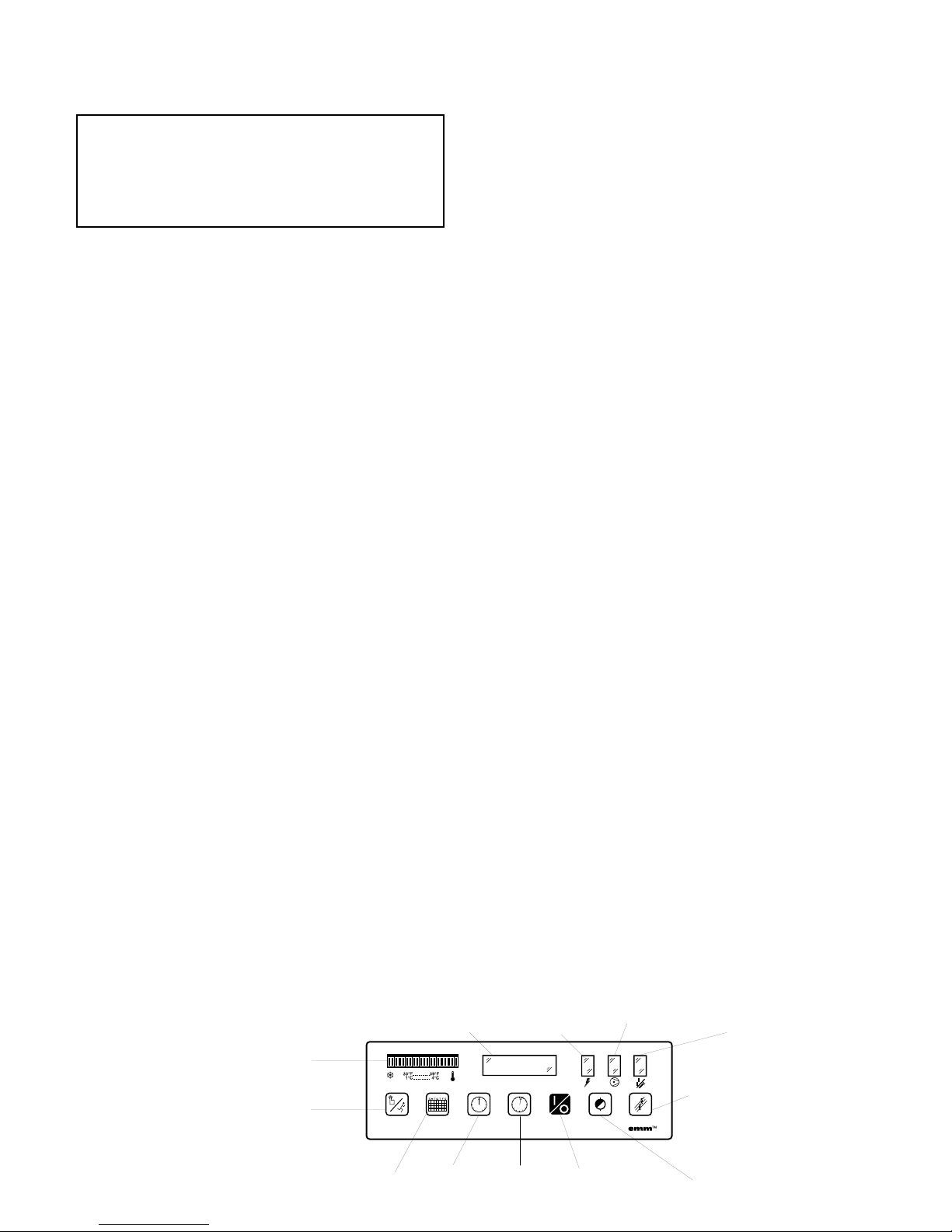
3. Check interface panel
NOTE: Interface panel will switch between Current Time/
Operating Status screen and Hours to Service/Total
Operating Hours (HRS TO SVC/TOTAL) screen. TOTAL is
cumulative hours of refrigeration compressor operation.
a. Verify that current time is correct
b. Check HRS TO SVC: this indicates time remaining
until service is required; allow time for required
maintenance items to be ordered
c. Check operating status:
MANUAL OVERRIDE - Dryer is either running
continuously (not being controlled by the
scheduled on/off times) or the refrigeration
compressor has been shut off using the
On/Off button.
SCHEDULE RUNNING - Refrigeration compressor
is being turned on and off by the monitor per-
programmed schedule ( see B.2. to set schedule)
d. Check Temperature indicator - indicator should
read in the green area
e. Check Alarm/Service light If illuminated, check
Interface panel.
1) I
f SERVICE DRYER appears, scheduled
maintenance time has elapsed (HRS TO SRV is 0).
Perform needed service and reset service
interval (see B.2.).
2). If ALARM appears, a dryer fault is indicated;
see Trouble-shooting Guide for possible
remedies. After fault correction push Reset
button to turn Fault alarm off.
FAULTS
LOW PRESSURE - the refrigeration compressor
control circuit has opened because of low
suction pressure. Compressor will restart
automatically when fault is corrected.
HIGH PRESSURE - the refrigeration compressor
control circuit has opened because of high
head pressure. The high pressure switch must
be reset manually once the fault is corrected.
Red reset button is located on pressure switch
inside unit.
LOW TEMPERATURE - compressed air
temperature is below the set point
NOTE: If temperature probe is open, one light on lefthand
side of Temperature indicator will be illuminated.
HIGH TEMPERATURE - compressed air tempera-
ture is above the set point.
NOTE: If temperature probe is shorted, Temperature
indicator will be completely illuminated.
DRAIN - electric drain contains a high water
level alarm that activates if drain fails to
discharge.
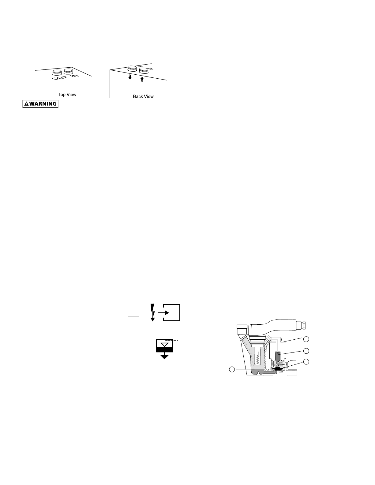
f. Check drain operation - push Drain (push-to-test)
button to energize electric drain. A flow of
condensate and/or air should be present at the
drain outlet.
E. Using the RS-232 port
The RS-232 port is used to monitor dryer operation
from a host computer. A (1 to 1) DB-9 cable is required
to connect dryer and computer. For PC connections,
data is transmitted on pin 2, received on pin 3, ground
is pin 5, pins 7 and 8 are jumpered at dryer.
Operation is at fixed baud rate of 2,400; asynchronous
format is 8 bit, no parity, 1 stop bit (“8,N,1”). No
checksum or error correction values are provided. If
required, request status string two (or more) times and
compare for agreement.
Request data by sending ASCII ? character (3FH).
Response may take up to two seconds as certain
processing functions may require completion before
serial port is acknowledged.
Dryer responds with line feed (0AH), carriage return
(0DH), and character string:
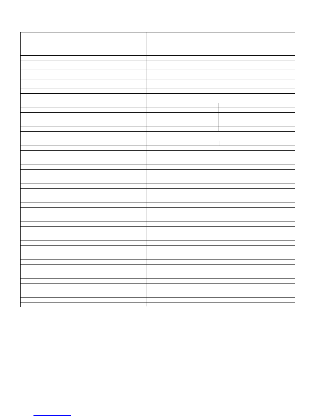
(1) (2) (3) (4) (5) (6) (7)
XXX, X, XXX, X, XXXX, XXXX, X
(1) Number of Temperature Indicator LEDs illuminated (1-20)
(2) Compressor state, C=X (1or 031H = ON, 0 or 030H= OFF)
(3) Sum of alarm weights, A=XXX (0 - 255;
e.g. high pressure and service alarms = 132 [4 + 128])
Bit Weight Alarm
2 4 High press. alarm (1 = alarm)
3 8 Low press. alarm (1 = alarm)
5 32 Drain alarm (1 = alarm)
7 128
Service (service required) alarm (1 = alarm)
For low and high temperature alarm, assign alarm to
number of Temperature Indicator LEDs illuminated:
3 = low, 20 = high
(4) Day of week (1 = Sunday, 7 = Saturday)
(5) Time (24 hour format, hour, minuteS)
(6) Hours to service (0-9999)
(7) Operating mode, M=X (S = schedule running,
M = manual override)
F. Using the auxiliary contacts
The monitor is equipped with an auxiliary set of dry
(volt-free) contacts (one set of normally open contacts,
one set of normally closed contacts) which can be used
to operate an auxiliary device (e.g., an air line solenoid
valve). Rating: 5 amps @ 24VDC or 240VAC
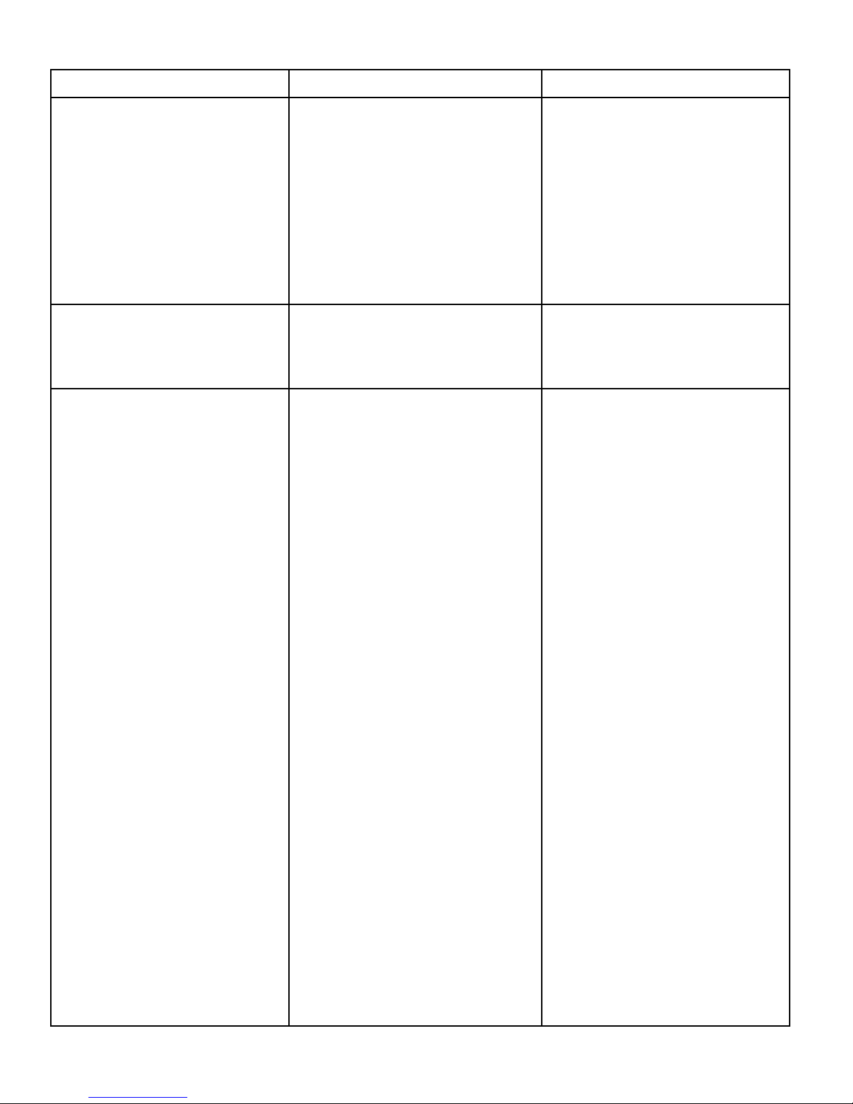
1. These contacts can be activated in one of the
following modes:
Schedule Driven Mode - the contacts will be energized
and de-energized according to the schedule inputted
by the operator of the dryer. If the refrigeration
compressor shuts down on a fault condition, the
contacts will remain energized (or de-energized)
according to the schedule. The contacts will operate
independently of the refrigeration compressor in both
the manual override and schedule running modes.
NOTE: The schedule driven mode is the factory
default setting.
For Sales & Service Call: 705-722-5747 Ext.1

7
COOLING MEDIUM*
AMBIENT
TEMPERATURE MULTIPLIER
°F °C
80 27 1.12
90 32 1.06
100 38 1.00
110 43 0.94
INLET COMPRESSED AIR CONDITIONS
INLETINLET TEMPERATURES
PRESSURES 80°F90°F 100°F 110°F 120°F
psig kgf/cm227°C32°C38°C 43°C49°C
50 3.5 1.35 1.05 0.84 0.69 0.56
80 5.6 1.50 1.17 0.95 0.79 0.66
100 7.0 1.55 1.23 1.00 0.82 0.70
125 8.8 1.63 1.31 1.07 0.91 0.74
150 10.5 1.70 1.37 1.13 0.95 0.80
175 12.3 1.75 1.42 1.18 0.99 0.84
200 14.0 1.80 1.47 1.22 1.03 0.89
3.1 Condenser coil—Clean off accumulated dust
and dirt monthly.
3.2 Moisture separator—Replace filter element
when pressure drop across dryer is excessive
or annually.
3.3 Check separator daily to be sure automatic drain
is discharging.
3.4 Blow down separator weekly by pushing test
button on control panel.
3.4 Rebuild drain mechanism annually.
To facilitate service, maintenance kits are available.
3.0 MAINTENANCE
SIZING
Determining dryer capacity at actual operating conditions
To determine the maximum inlet flow capacity of a dryer
at various operating conditions, multiply the rated capacity
from Table 1 by the multipliers shown in Table 2.
Example: How many scfm can an air-cooled model 400
handle when compressed air to be dried is at 200 psig and
100°F; ambient air temperature is 80°F; and a 40°F dew
point temperature is desired?
Answer: 400 x 1.22 x 1.12 x 1.1 = 601 scfm.
TABLE 2
Air capacity correction factors (Multipliers)
MODEL 200 250 300 400 500 750
Rated capacity of 60 Hz 200 250 300 400 500 750
air-cooled models (scfm) 50 Hz 170 210 250 340 420 630
TABLE 1
Rated capacity (scfm) and pressure drop @ 100 psig inlet
pressure, 100°F inlet temperature, and 100°F ambient
temperature
*Air-cooled models; water-cooled models use 1.15 multiplier if cooling
water is below 35
°
C, 95
°
F.
Element o-ring Separator Element
Bowl o-ring
Threads
Threads
OUTLET DEWPOINT
DEWPOINT
TEMPERATURE MULTIPLIER
°F °C
38 3 1.0
40 4 1.1
45 7 1.2
50 10 1.3
Dryer Driven Mode- the contacts will be energized
and de-energized in parallel with the refrigeration
compressor of the dryer. Therefore, if the refrigera-
tioncompressor is on, the contacts are energized; if
the refrigeration compressor is off (manually or by a
system fault condition), the contacts will be de-
energized.
NOTE: It is the responsibility of the end-user to properly
design the system control circuitry when using the
auxiliary contact feature.
To select Schedule Driven or Dryer Driven modes:
1. De-energize unit and disconnect the power
supply to the dryer.
2. Remove the cabinet panels as necessary to
provide access to the Monitor panel.
3. On the rear of the circuit board, locate the
jumper pins labeled JA and JB.
4. Move the jumper to the appropriate setting:
Schedule Driven: jumper position JA
Dryer Driven: jumper postion JB
5. Wire the auxiliary device into the terminals
1 (Normally Open), 2 (Common) and/or 3
(Normally Closed) on the terminal block TB2.
See wiring diagram for details.
6. Reinstall the cabinet panels.
7. Energize the unit.
For Sales & Service Call: 705-722-5747 Ext.1

8
ENGINEERING DATA
MINIMUM - MAXIMUM OPERATING CONDITIONS
Min.-Max. Inlet Air Pressure (compressed air at inlet to dryer) 30-200 psig (2.1-14 kgf/cm2)
Max. Inlet Air Temperature (compressed air at inlet to dryer) 120°F (49°C)
Min.-Max. Ambient Temperature
Air-cooled 45°F (7°C) - 110°F (43°C)
Water-cooled 45°F (7°C) - 130°F (54°C)
REFRIGERATION SYSTEM DATA
Compressor Type Hermetic - Non-Cycling
Refrigeration Compressor Horsepower 1 1-1/2 2 3
BTU/HR -
Refrigeration Only @ 35°F Evaporator & 100°F Ambient
60/50 Hz
8660 / 7217 15600 / 13000 17400 / 14500 26700 / 22250
Outlet Air Temperature (nominal at rated conditions) 85°F (29°C)
Refrigerant Type R-134a
Refrigerant Charge See dryer serial number tag
Suction Pressure Setting (controlled by hot gas by-pass valve) 31.5 31.5 31.5 31.5
Compressor Control Ranges (psig) (out-in) High 281-190 281-190 281-190 281-190
Low 24-34 24-34 24-34 24-34
Condenser Fan Switch Setting (in-out)(psig) Fan 1 113-78 113-78 113-78 113-78
(air-cooled models) Fan 2 - - 183-124 183-124
Air Flow Across Condenser (cfm) (air-cooled models)
60/50 Hz
672 / 560 1093 / 911 2650 / 2208 2650 / 2208
Condenser Cooling Water Requirements (water-cooled models)
Recommended Water Pressure (psig) 40 Min. - 120 Max*.
Gallons Per Minute Of Flow Required With 85°F Cooling Water
60/50 Hz
2.9/2.4 4.8/4.0 5.8/4.8 12/10
Inlet Water Connection 1/2” Female
ELECTRICAL
Nominal Voltage 208-230/3/60 208-230/3/60 208-230/3/60 208-230/3/60
Max.- Min. voltage 253-187 253-187 253-187 253-187
Rated Load Amps** 8.4 11.5 13.6 22.9
Locked Rotor Amps** 51 65.5 75 90
Minimum Circuit Ampacity 10.5 16.9 17.1 31.7
Branch Circuit Fuse Size (amps) 15 20 25 45
Watts @ 35°F Evaporator & 100°F Ambient 1335 1940 2620 3600
Resistance (Ohms) Three phase (Total) 1.77 1.256 1.058 0.853
Nominal Voltage 460/3/60 460/3/60 460/3/60 460/3/60
Max. - Min. Voltage 506-414 506-414 506-414 506-414
Rated Load Amps** 4.0 4.9 6.2 11
Locked Rotor Amps** 25 33 40 45
Minimum Circuit Ampacity 5.2 9.2 9.6 15.6
Branch Circuit Fuse Size (amps) 15 15 15 20
Watts @ 35°F Evaporator & 100°F Ambient 1335 1940 2620 3600
Resistance (ohms) Three phase (Total) 7.44 4.95 4.11 0.853
Nominal Voltage 380-420/3/50 380-420/3/50 380-420/3/50 380-420/3/50
Max. - Min. Voltage 462-342 462-342 462-342 462-342
Rated Load Amps** 4.0 4.9 5.7 9.9
Locked Rotor Amps** 25 33 45 45
Minimum Circuit Ampacity 5.2 9.2 9.6 15.6
Branch Circuit Fuse Size (amps) 15 15 15 20
Watts @ 35°F Evaporator & 100°F Ambient 1068 1552 2096 3030
Resistance (ohms) Three phase (Total) 7.44 4.95 4.11 0.853
Nominal Voltage 575/3/60 575/3/60 575/3/60 575/3/60
Max. - Min. Voltage 632-518 632-518 632-518 632-518
Rated Load Amps** 3.2 3.9 4.6 7.9
Locked Rotor Amps** 25 33 40 45
Minimum Circuit Ampacity 4.2 7.4 7.7 12.8
Branch Circuit Fuse Size (amps) 15 15 15 15
Watts @ 35°F Evaporator & 100°F Ambient 1335 1940 2620 3600
Resistance (ohms) Three phase (Total) 7.44 4.95 4.11 0.853
MODELS 200 250 & 300 400 & 500 750
* Allows continued operation with some restriction in the water strainer
** Air-cooled models only
For Sales & Service Call: 705-722-5747 Ext.1

9
DIMENSIONS / WEIGHTS
Dimensions
inches
Model 200-300 400-500 750
A 40-1/8 52-1/8 57-7/16
B48 5165
C 21-3/4 27-1/2 27-1/2
D 2-3/4 5 5
E8 9 9
F 2-13/16 3-1/4 3-1/4
G 4-1/8 4-1/8 4-1/8
H 6-5/8 8 19-3/8
I 3-1/2 3-1/2 3-1/2
J 6-1/4 6-1/4 6-1/4
K 1-1/4 1-1/4 1-1/4
L 1-1/8 2-1/4 2-1/4
Inlet/Outlet Connections 2” 3” 3”
IN OUT
D
E
Top View
J
L
Left SideView FrontView Right SideView
I
A
C
G
H
B
K
F
AIR FLOWAIR FLOW
Model 200 250 300 400 500 750
Weight (lb) 405 415 416 457 498 625
LEGEND
CON - CONTACTOR
HTR - CRANKCASE HEATER
MTR - COMPRESSOR
1FU - FUSE, SECONDARY
2FU - FUSE, PRIMARY
3FU - FUSE, PRIMARY
1FM - FAN MOTOR #1
2FM - FAN MOTOR #2,
1FPS - FAN PRES. SWITCH #1
2FPS - FAN PRES. SWITCH #2
TC1 - DEWPOINT TEMPERATURE
T1 - TRANSFORMER CONTROL
T2 - TRANSFORMER, HDD BOARD
SSMP - SOLID STATE MOTOR PROTECTION
SOL1 - DEMAND DRAIN
ELECTRICAL SCHEMATIC
NOTE: Dimensions and Weights are for reference only. Request certified drawings for construction purposes.
(1) Models 200, 250, 300 -
Air flow is from the front
to back of the dryer.
Models 400, 500, 750 - Air
flow is from right to left of
the dryer. (1)
For Sales & Service Call: 705-722-5747 Ext.1

10
TROUBLESHOOTING GUIDE
C) Checkpoint faults
1. Power on/off light
2. Compressor on light off
3. Alarm/Service alert light on -
check Display for active
conditions
SERVICE DRYER
LOW PRESSURE
HIGH PRESSURE
NOTE: If high refrigerant pressure
occurs, switch must be manually
LOW TEMPERATURE
(also observed as low reading
on temperature indicator)
HIGH TEMPERATURE
(also observed as high reading on
temperature indicator)
DRAIN
TIME OUT
A) Water downstream of dryer 1. Residual free moisture remaining in
downstream pipelines
2. Air by-pass system is open
3. Inlet and Outlet connections are
reversed
4. Air lines downstream of dryer are
exposed to temperatures below the
dew point.
5. Excessive free moisture (bulk liquid)
at dryer inlet
6. Condensate not being drained
7. Dryer overloaded resulting in
elevated dew point.
8. Refrigeration system not functioning
1. Excessive air flow
2. Freezing of moisture in evaporator
because of refrigeration system
fault
3. Filter loaded with solid particulates
a. Power failure; open circuit
a. Compressor commanded off by
manual switch or programmed
schedule
b. Open circuit
c. Control circuit open on high or low
pressure cutout
Service interval specified has elapsed
a. Hot gas by-pass valve requires
adjustment
b. Low on refrigerant
a. Lack of condenser cooling
Air-cooled - Ambient temperature
too high, clogged condenser fins,
obstructed flow across condenser,
faulty fan motor or fan
control switch.
Water-cooled - Cooling
temperature too high, flow too low,
clogged strainer, faulty water
regulating valve
a. Hot gas by-pass valve
requires adjustment
a. Dryer overloaded
b. Refrigeration system off or not
cooling sufficiently
a. Drain line restricted or frozen
b. Drain mechanism faulty
Dryer left in the Set Mode for longer
than 30 seconds
Blow out system with dry air
Check valve positions
Check for correct connection
Insulate or heat trace air lines exposed
to low ambients or dry air to lower
dew point
Install separator ahead of dryer
See C below
B) High pressure drop across dryer
SYMPTOM POSSIBLE CAUSE(S) CORRECTIVE ACTION
See C below
See C below
Check flow rate
See C below
Replace filter element
Check for power to dryer
Check current command status
Check power ro compressor
Check display for fault
Perform scheduled service
Contact qualified technician or
manufacturer’s service department
Check air temperature 6” in front
of condenser
Clean condenser and check for free
air flow
Check fan and switch operation
Check cooling medium temperature
and flow, clean strainer, check
valve operation
Contact qualified technician or
manufacturer’s service department
Check compressed air flow,
temperature, and pressure
Check power to unit, power to
compressor, Low or High pressure
faults Have qualified technician
evaluate system
Open drain line
Turn 3-way valve to horizontal position
and open petcock for manual draining.
Rebuild drain mechanism
.
Finish programing and press
Set/Run button
NOTE: After fault correction, press reset button to clear display
For Sales & Service Call: 705-722-5747 Ext.1

11
PARTS LIST
208-230/3/60 380-420/3/50, 460/3/60, and 575/3/60
PARTS DESCRIPTION 200 250,300 400,500 750 200 250,300 400,500 750
Condensing Unit
(air-cooled) 4130.127.16 4130.127.19 4130.125.14 4130.129.1 4130.127.17 4130.127.20 4130.125.15 4130.129.2
Compressor 4130.108.53 4130.108.55 4130.108.57 4130.108.64 4130.108.54 4130.108.56 4130.108.58 4130.108.65
Fan motor 6105.238.37 6105.238.39 6105.238.39 6105.238.39 6105.238.38 6105.238.40 6105.238.40 6105.238.40
Fan blade 4140.227.22 4140.227.23 4140.227.24 4140.227.24 4140.227.22 4140.227.23 4140.227.24 4140.227.24
Crankcase heater 5920.327.12 5920.327.12 5920.327.12 5920.327.12 5920.327.13 5920.327.13 5920.327.13 5920.327.13
Condenser (air-cooled) 4130.111.23 4130.111.24 4130.111.25 4130.111.28 4130.111.23 4130.111.24 4130.111.25 4130.111.28
Low refrigerant
pressure switch 4130.138.22 4130.138.22 4130.138.22 4130.138.22 4130.138.22 4130.138.22 4130.138.22 4130.138.22
High refrigerant
pressure switch 4130.138.25 4130.138.25 4130.138.25 4130.138.25 4130.138.25 4130.138.25 4130.138.25 4130.138.25
Fan cutout switch 1 4130.138.23 4130.138.23 4130.138.23 4130.138.23 4130.138.23 4130.138.23 4130.138.23 4130.138.23
Fan cutout switch 2 --- --- 4130.138.24 4130.138.24 --- --- 4130.138.24 4130.138.24
Condenser
(water-cooled) 4130.137.44 4130.108.62 4130.108.46 --- 4130.137.45 4130.108.63 4130.106.47 4130.106.56
Water control valve 4130.145.22 4130.145.22 4130.145.22 --- 4130.145.22 4130.145.22 4130.145.22 4130.145.23
Water strainer 4731.735.1 4731.735.1 4731.735.1 --- 4731.735.1 4731.735.1 4731.735.1 4731.735.1
Screen, water strainer 4731.735.5 4731.735.5 4731.735.5 --- 4731.735.5 4731.735.5 4731.735.5 4731.735.5
Maintenance Kits RDMK6C RDMK7C RDMK8C RDMK9C RDMK6C RDMK7C RDMK8C RDMK9C
For Sales & Service Call: 705-722-5747 Ext.1

SERVICE DEPARTMENT: (724) 746-1100
Devair Inc.
Formerly DeVilbiss Air Compressor Products
P.O. Box 3000 Barrie, Ontario L4M 4V6
Tel: (705) 728-5657
Warranty
The manufacturer warrants the product manufactured by it, when properly installed, operated, applied and
maintained in accordance with procedures and recommendations outlined in the manufacturer’s instruction manuals,
to be free of defects in material and workmanship for a period of one (1) year from date of purchase at the retail level
by the end user, not to exceed eighteen (18) months from the date of manufacture, provided such defect is
discovered and brought to the manufacturers attention within the aforesaid warranty period.
The manufacturer will repair or replace any product or part determined to be defective by the manufacturer within
the warranty period, provided such defect occurred in normal service and not as the result of misapplication, misuse,
abuse, neglect, incorrect maintenance, accident, or normal wear. Normal maintenance items requiring routine
replacement are not warranted.
The warranty covers parts and labour for the warranty period. Repair or replacement shall be made at the sole option
of the manufacturer. Any service performed on the product by anyone other than the manufacturer must first be
authorized by the manufacturer. Unauthorized service voids the warranty and any resulting charge or subsequent
claim will not be paid.
Products repaired or replaced under warranty shall be warranted for the unexpired portion of the warranty applying to
the original product, based on the original date of purchase and/or date of manufacture, as outlined above.
There is no other expressed warranty. Implied warranties including those of merchantability and fitness for a particular
purpose are limited to one (1) year from date of purchase to the extent permitted by law and any and all implied
warranties are excluded. This is the exclusive remedy. Liability for consequential damages under any and all warranties
are excluded to the extent exclusion is permitted by law.
This warranty gives you specific legal rights, and you may also have other rights within your jurisdiction.
This warranty does not cover:
1. Merchandise that has become inoperative because of ordinary wear, misuse, negligence, accident, or improper
and unauthorized repair or alteration.
2. Costs occasioned by the removal, replacement, or repair of merchandise (other than by Devair) without
previous written authorization.
3. Expenses incurred in travel or lodging beyond a 40 kilometer (25 mile) distance from the nearest Devair
Authorized Service Centre, unless approved by Devair in advance.
4. Products, parts, materials, components, or accessories manufactured by others or supplied in connection with
the sale of the manufacturers products.
5. Repair and transportation costs of merchandise determined not to be defective under the terms and
conditions of this warranty.
All decisions by Devair Inc. with regard to this policy shall be final. Devair will not be responsible for any claimed
defective materials returned other than in accordance with this statement of policy or without our prior authorization.
12
For Sales & Service please contact:
CENTRAIR Air Systems & Supplies
Phone: 705-722-5747
Fax: 705-722-5458
Email: [email protected]
Website: www.centrair.ca
Table of contents
Other Devair Dryer manuals