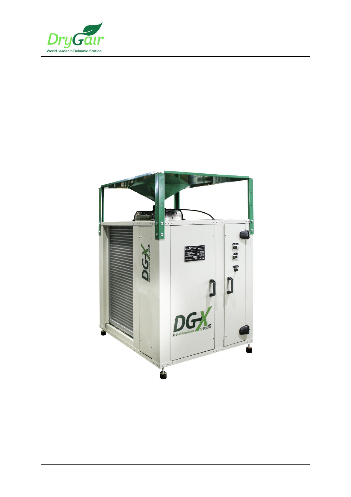
DryGair Dehumidification Unit Model DG-X
Safety
Ver. 12/2020
3
2. SAFETY
DryGair Energies Ltd. believes that the safety of personnel working with and
around the unit is the most important consideration. The DryGair unit is
equipped with all the safety devices necessary to ensure risk-free use under
standard conditions.
Machine installation, maintenance, and adjustments must be performed only
by a qualified technician with expert machine knowledge and that has read
this manual.
Before operating the unit or performing maintenance operations, read and be
familiarized with the safety information.
•Obey and follow all warnings and cautions given in this manual.
•Comply with all approved and established precautions for operating
electrical and mechanical equipment.
•Only qualified and authorized personnel should perform maintenance or
repair tasks.
•Verify the power, and any other connected facilities, are turned off and
disconnected before beginning maintenance procedures, part
replacements, or repairs.
•We advise strict observance of the work safety standard as defined by the
authorities in each country.
DryGair cannot accept responsibility for injury to persons or damage to
objects resulting from not observing safety standards.
2.1 Hazards
Danger: Electrical Shock Hazard. High voltage is present at points throughout the
Unit. Contact with high voltage can result in injury or death. Before performing any
operation related toelectricity, open the electric compartment cover, switchoffthe
Main Power switch and switch off the CircuitBreaker. Doing so ensures no voltage
is present.
Danger: Hot Surface Hazard. The heat exchangers and their pipes, andthe
compressor may have a high temperature during unit operation. Do not touch the
compressor and the heat exchanger pipes and coils while the unit is operating.
Verify the unithas cooled down before touchingthem.
Danger: Bodily Injury Hazard. Be careful not to drop any of the unit parts.
Dropping the Covers mightcause bodily injury or damage to the parts.