INDEX
1CE CONFORMITY DECLARATION.......................................... 6
2Electrical connections...................................................................... 7
2.1 Rear terminal boards .......................................................................................................7
2.2 Power supply connections................................................................................................7
2.2.1 Accepted power supply................................................................................................7
2.3 Connection of I1 single channel input card for 80 mV differential signal ......................8
2.4 Connection of I2 two channels input card for 80 mV differential signal ........................8
2.5 Connection of I4 single channel input card for 0-5 V and 0-10 V signals ......................8
2.6 Connection of I6 single channel input card for 4-20 mA and 0-20 mA (2 wire) signals 8
2.7 Connection of I10 single channel input card for Start-Stop digital signal......................9
2.8 Connection of output cards O1 = 0-5 V and O2 = 0-10 V...............................................9
2.9 Connection of output cards O3 = 4-20 mA and O4 = 0-20 mA .....................................9
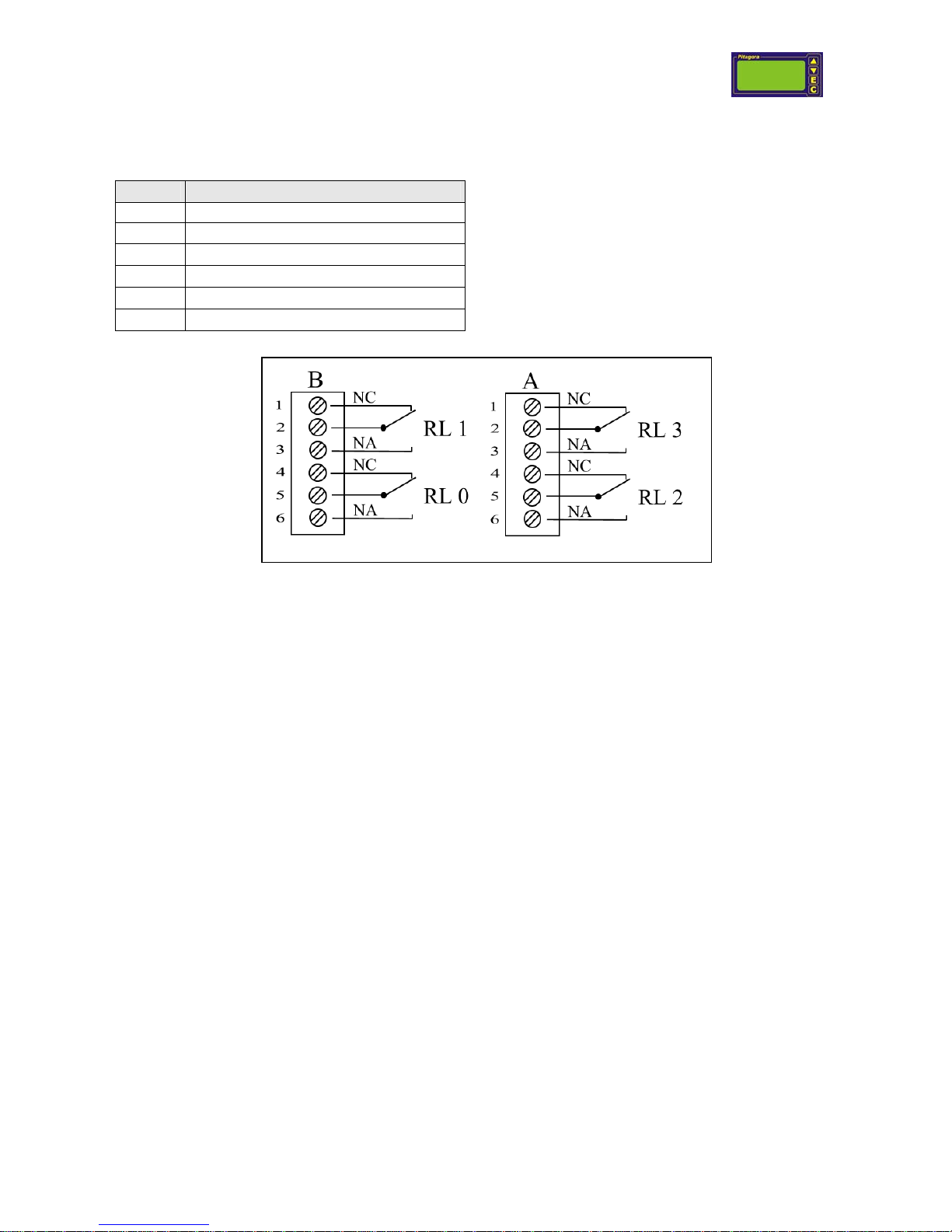
2.10 Connection of D0 card, two relays alarm level..............................................................10
2.11 Connection of D1 card, four optically insulated alarm levels .......................................11
2.12 Connection of external contacts.....................................................................................12
2.13 Connection of grounding for CE regulation ..................................................................12
2.14 Connection of RS232 serial port (COM1) .....................................................................13
2.15 Connection of RS485 (RJ-11b connector) serial com port............................................13
2.15.1 Terminator Resistances ..............................................................................................14
3Menu setting – general sequence .................................................. 14
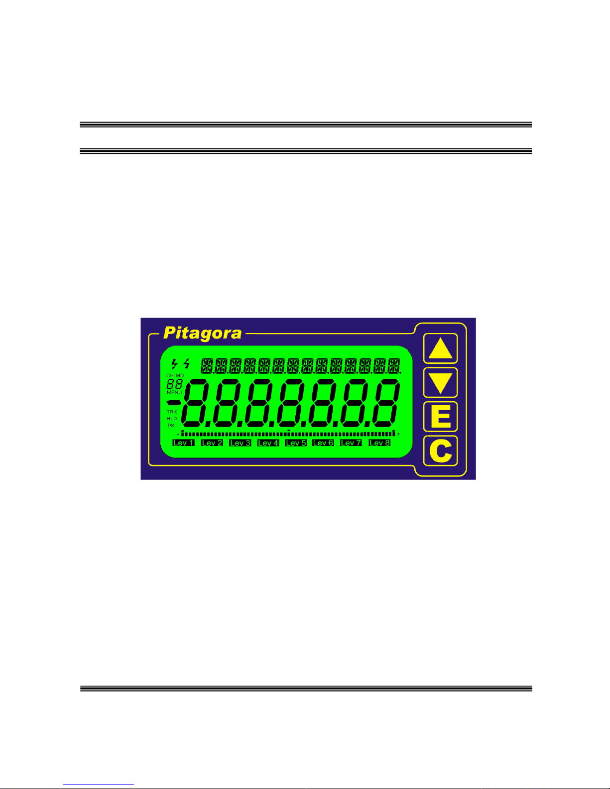
4Display............................................................................................. 15
5Instrument setting.......................................................................... 16
6AdC setting (I1 or I4 input cards)................................................... 18
7dAC setting (O1, O2, O3, O4 analog output cards)....................... 21
8Md setting (Modbus communication setting)................................ 22
9LEV alarm level setting.................................................................... 23
10 MAG setting (I10 Start Stop input card)......................................... 24
11 LCD display setting........................................................................ 25
12 Return to Measure modality......................................................... 25
13 Introduction to measure modes .................................................... 26
14 Two channel summing unit (MD=1)............................................. 27
15 Three channel summing unit (MD=2).......................................... 28
16 Four channel summing unit (MD=3)............................................ 29
17 Four channel summing unit – analog output (MD=4)................ 30
18 Four channel summing unit (MD=5)............................................ 31
19 Four channel summing unit – analog output (MD=6)................ 32