DSI Life Science Suite ACQ-7700 User manual

-~
ARTISAN
®
~I
TECHNOLOGY
GROUP
Your definitive source
for
quality
pre-owned
equipment.
Artisan Technology
Group
Full-service,
independent
repair
center
with
experienced
engineers
and
technicians
on staff.
We
buy
your
excess,
underutilized,
and
idle
equipment
along
with
credit
for
buybacks
and
trade-ins
.
Custom
engineering
so
your
equipment
works
exactly as
you
specify.
•
Critical
and
expedited
services
•
Leasing
/
Rentals/
Demos
• In
stock/
Ready-to-ship
•
!TAR-certified
secure
asset
solutions
Expert
team
ITrust
guarantee
I
100%
satisfaction
All
tr
ademarks,
br
a
nd
names, a
nd
br
a
nd
s a
pp
earing here
in
are
th
e property of
th
e
ir
r
es
pecti
ve
ow
ner
s.
Find the Data Sciences International / LDS / Gould ACQ-7700 at our website: Click HERE

Life Science Suite
ACQ-7700 Installation
Manual
Model: PNM-P3P-7001
Manual: MU00225-001
Revision 51
Data Sciences International
119 14th Street NW
St. Paul, MN 55112
P: +1 (651) 481.7400 •F: +1 (651) 481.7404
www.datasci.com
Artisan Technology Group - Quality Instrumentation ... Guaranteed | (888) 88-SOURCE | www.artisantg.com

Data Sciences International
119 14th Street NW
St. Paul, MN 55112
P: +1 (651) 481.7400 •F: +1 (651) 481.7404
www.datasc
i.com
DSI/Ponemah Life Science products are not “medical devices” intended to be used for the purposes of diagnosis of
disease or other conditions, or in the cure, mitigation, treatment, or prevention of disease, or used as a life support
device. Use of DSI/Ponemah products are solely for the purposes of conducting life science research.
Copyright2003-2008 by Data Sciences International. All rights reserved. No part of this manual may be reproduced,
translated, transcribed, or transmitted in any form or by any means manual, electronic, electromagnetic, chemical, or
optical without the written permission of Data Sciences International.
Artisan Technology Group - Quality Instrumentation ... Guaranteed | (888) 88-SOURCE | www.artisantg.com

ACQ-7700 / Type 3 Installation Manual System Overview •i
Contents
System Overview 4
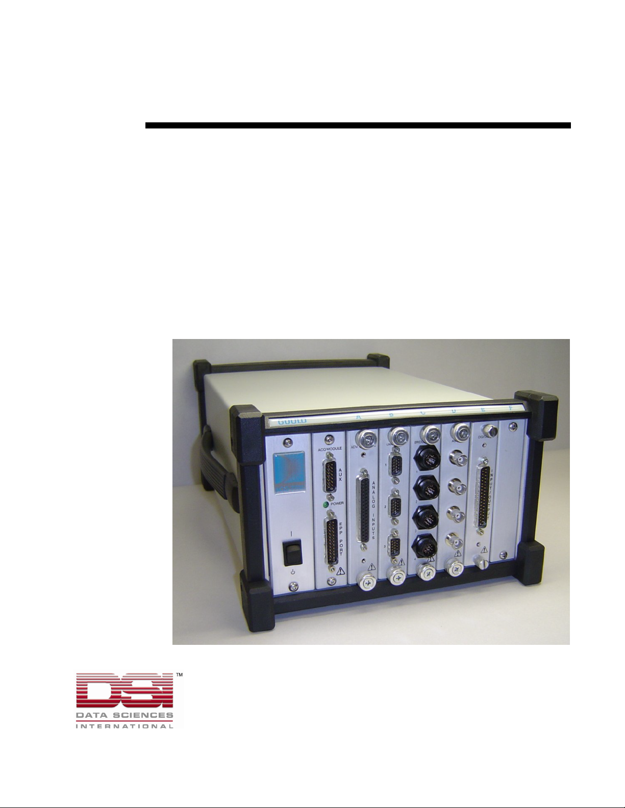
ACQ-7700 Acquisition Interface Unit.......................................................................................4
ACQ-7700 Signal Conditioners.................................................................................................4
System Requirements ................................................................................................................5
Configuring the System 6
Assistance ..................................................................................................................................6
Initial Inspection ........................................................................................................................6
Parts List....................................................................................................................................6
EPP Interface Card Installation..................................................................................................7
Software Installation..................................................................................................................7
Installing ACQ-7700 Signal Conditioners.................................................................................8
Removing ACQ-7700 Signal Conditioners ...............................................................................8
Installing the ACQ-7700 Acquisition Interface.........................................................................8
ACQ-7700 Connections.............................................................................................................9
EPP Port Connection ...................................................................................................9
Auxiliary Connector (Preview Feature).....................................................................10
Power Connection .....................................................................................................10
Getting Started 11
Introduction .............................................................................................................................11
Starting the Program................................................................................................................11
Calibration of Amplifiers.........................................................................................................12
Product Information...................................................................................................13
Maintenance 15
Introduction .............................................................................................................................15
Cleaning...................................................................................................................................15
General ......................................................................................................................15
Filter ..........................................................................................................................15
Re-Certification of Performance..............................................................................................15
Appendix 17
Specifications...........................................................................................................................17
Troubleshooting.......................................................................................................................18
Interface Configuration............................................................................................................18
Declaration Electromagnetic Emissions/Immunity 19
Electromagnetic Emissions/Immunity Tables .........................................................................19
Product Issue Report 25
Artisan Technology Group - Quality Instrumentation ... Guaranteed | (888) 88-SOURCE | www.artisantg.com

ii •System Overview ACQ-7700 / Type 3 Installation Manual
Product Issue Report Form ......................................................................................................25
Feature Request 26
Feature Request Form..............................................................................................................26
Artisan Technology Group - Quality Instrumentation ... Guaranteed | (888) 88-SOURCE | www.artisantg.com

ACQ-7700 / Type 3 Installation Manual System Overview •1
Safety
This general safety information is for both user and service personnel. Specific WARNINGS and CAUTIONS
will be found throughout the manual where applicable. Please refer to the Sécurité section for the French
translation of this safety section.
TERMS AND SYMBOLS IN THIS MANUAL AND ON THE EQUIPMENT
CAUTION, this symbol indicates paragraphs providing cautionary and detailed
information about a specific part of the instrument. That part of the equipment is
also marked with this symbol (See references to this symbol in the manual).
WARNING, risk of electric shock
AC, Alternating current
Type CF Equipment
Equipotentiality / Chassis ground
STANDBY (Power is on, instrument off in standby mode)
ON (connection to AC mains)
DSI/Ponemah Life Science products are not “medical devices” intended to be used for the purposes of diagnosis of
disease or other conditions, or in the cure, mitigation, treatment, or prevention of disease, or used as a life support
device. Use of DSI/Ponemah products are solely for the purposes of conducting life science research.
WARNING
IF THIS INSTRUMENT IS OPERATED OR USED IN A MANNER NOT SPECIFIED, THE
PROTECTION PROVIDED BY THE SYSTEM MAY BE IMPAIRED. DO NOT USE IN THE
PRESENCE OF FLAMMABLE ANESTHETICS.
Artisan Technology Group - Quality Instrumentation ... Guaranteed | (888) 88-SOURCE | www.artisantg.com

2•System Overview ACQ-7700 / Type 3 Installation Manual
POWER SOURCE
This instrument is intended to operate indoors from a power source that does not apply more than 250 volts
RMS between the supply conductors or between either supply conductor and ground. A protective ground
connection by way of the grounding conductor in the power cord is required. If the unit is mounted in a
permanent installation (i.e. rack-mounted), then the user MUST provide access to the plug OR connect the
instrument to a circuit with a user accessible breaker or power switch. The detachable power cord is the means
by which the mains are disconnected.
PROPERLY GROUND THE INSTRUMENT
This instrument is grounded through the power cord. It is a Class 1 Device. Grounding reliability can only be
achieved when the equipment is connected to a hospital grade receptacle. Use only the power cord and
connector specified for your instrument. Use only a power cord that is in good condition.
Upon loss of the protective-ground connection, all accessible conductive parts (including knobs and controls
that may appear to be insulating) may render an electric shock.
USE PROPER TEST LEADS AND CABLES
Test leads and/or interconnect cables may carry HAZARDOUS live voltages. They must be examined regularly
for wear. Worn leads or cables should be replaced.
The amplifier has been designed and tested for protection against the effects of the discharge of a cardiac
defibrillator. For safe operation, use only the cables provided with the amplifier.
ECG ELECTRODE PLACEMENT
The user should assure that any electrodes used, including the neutral electrode, do not contact any conductive
parts, including earth.
Whenever a defibrillator is used, assure that the leads are placed on the appropriate places on the subject. Leads
should never be placed on grounded surfaces. Verify that defibrillator leads are NOT placed directly on the
ECG electrodes.
DO NOT USE WITH HF SURGICAL EQUIPMENT
It is imperative that the ECG electrodes be removed from the subject before using any HF surgical equipment.
This equipment DOES NOT provide protective means against burns when used with HF surgical equipment.
SUMMATION OF RISK CURRENT
The amplifier has been designed and tested to meet safe leakage current specifications when attached to the
subject. Any additional equipment added to the subject may increase leakage. The operator should be aware of
the possible summation of additional leakage currents when additional equipment is connected to the subject.
USE WITH PACEMAKERS
The operator should be aware of any possible interactions or safety hazards when the amplifier is used in
conjunction with cardiac pacemakers and other stimulant devices. The manufacturer of these devices should be
consulted for additional information.
Artisan Technology Group - Quality Instrumentation ... Guaranteed | (888) 88-SOURCE | www.artisantg.com

ACQ-7700 / Type 3 Installation Manual System Overview •3
EMI/RFI
The amplifier has been tested to meet EMI/RFI susceptibility and radiation standards. However, the user should
be aware of possible electromagnetic interactions between this device and other devices in the same area and
correct the situation as needed.
WARNINGS FOR AUTHORIZED SERVICE PERSONNEL
Dangerous voltages exist at several points in this instrument. To avoid personal injury, do not touch exposed
connections or components while power is on. Disconnect power before removing protective panels, soldering,
or replacing components.
USE THE PROPER FUSE
To avoid fire hazard, use only a fuse of the correct type, voltage rating, and current rating as specified in the
parts list for your instrument.
DO NOT OPERATE WITHOUT COVERS AND PANELS INSTALLED
To avoid personal injury and equipment damage, the user should disconnect power before removing covers,
panels or any grounding straps. Reinstall covers, panels, and any grounding straps before reconnecting power.
Artisan Technology Group - Quality Instrumentation ... Guaranteed | (888) 88-SOURCE | www.artisantg.com

4•System Overview ACQ-7700 / Type 3 Installation Manual
System Overview
ACQ-7700 Acquisition Interface Unit
The ACQ-7700 Acquisition Interface Unit is one of the available acquisition
interfaces for the DSI/Ponemah Life Science Suite (LSS). An acquisition interface
unit interfaces signals into the Ponemah Physiology Platform (P3 Plus).
The ACQ-7700 has a modular design which allows the user to easily expand the
number of available acquisition inputs to a maximum of 128, through the installation
of various signal conditioners. The portable, rugged chassis is perfect for interfacing
to a laptop, allowing for system mobility. The ACQ-7700 interfaces to the computer
by an Enhanced Parallel Port (EPP). This is the only required user connection to the
host computer. The aggregate sampling rate may be affected by the computers
performance and the complexity of the real time analysis being performed.
The recommended orientation of the ACQ-7700 is flat on a table with the grill of the
filter on the bottom.
ACQ-7700 Signal Conditioners
The ACQ-7700 can accept up to six signal conditioners that are fully programmable.
These signal conditioners are inserted into guided slots and secured by a positive
threaded latching system.
Signal conditioner setup is performed using a graphic user interface. All parameters
can be programmed directly in your test parameter units, reducing potential data
conversion errors. All setup parameters can be saved as a logical protocol name for
later recall, saving set up time. Because the system is completely integrated, these
parameter names and units are automatically transferred and utilized throughout the
system including all monitoring and analysis. The P3 Plus software handles all
control and communication with the ACQ-7700 signal conditioners. You do not
have to load any additional software. When the system is started, the P3 Plus
software will automatically interrogate the system and identify the ACQ-7700 signal
conditioners and their slot placement.
Artisan Technology Group - Quality Instrumentation ... Guaranteed | (888) 88-SOURCE | www.artisantg.com

ACQ-7700 / Type 3 Installation Manual System Overview •5
System Requirements
The system requirements for the ACQ-7700 are the same as the P3 Plus application
with the following differences.
•PCI EPP Interface Card - part number P01926.
•Your choice of instrumentation signal conditioning modules and analysis
modules.
Please view the P3 Plus Manual for system requirements.
For information on DSI/Ponemah products and services, check out our website at
www.ponemah.com.
Artisan Technology Group - Quality Instrumentation ... Guaranteed | (888) 88-SOURCE | www.artisantg.com

6•Configuring the System ACQ-7700 / Type 3 Installation Manual
Configuring the System
Assistance
If you require assistance in configuring your system, contact our Technical Support
department at (216) 328-7000. You can also request assistance from our support
department by contacting us through our web site at www.ponemah.com or email us
at lifescience@datasci.com.
Initial Inspection
Prior to attempting any electrical connections or operation, visually examine the unit
for any damage.
Parts List
The following comprise the system:
•ACQ-7700 - Acquisition Interface
•P01255 - IEEE 1284 Parallel Port Interface Cable
•P01926 - EPP Parallel Interface Card
•ACQ-7700 Signal Conditioners
•MU00225 ACQ-7700 / Type 3 Installation Manual
Artisan Technology Group - Quality Instrumentation ... Guaranteed | (888) 88-SOURCE | www.artisantg.com

ACQ-7700 / Type 3 Installation Manual Configuring the System •7
EPP Interface Card Installation
If the system was delivered with a configured computer or if the on board computer
LPT port is going to be used, these steps can be skipped. It is highly recommended
that the EPP parallel interface card be used as the interface to the ACQ-7700.
1. Make sure that the personal computer power cord is unplugged.
2. Remove the cover from the personal computer to expose the expansion
slots.
3. Verify that the EPP Interface card is configured as EPP for LPT2.
Refer to the documentation supplied with the EPP card to change the
configuration settings.
4. Install the card into an open PCI slot.
5. Reinstall the personal computer cover.
6. Plug in the computers power cord, and boot the computer.
7. Follow the device driver installation procedure provided by the
manufacturer.
Software Installation
If you did not purchase a complete system with everything installed and tested, you
will need to install the P3 Plus software. For the Acquisition Interface to operate
correctly, you must install the software onto the hard disk of the personal computer.
The procedures are outlined in the Ponemah Physiology Platform reference manual.
For the ACQ-7700 interface to work, the user must select ACQ-7700 as the
acquisition device in the Acquisition Interface tab of the Application
Configuration dialog. This dialog is opened by selecting Application
Configuration from the Options menu from within the P3 Plus application. The
LPT Port and Port Mode must also be set to the correct settings. The LPT Port is
the port that the ACQ-7700 is connected to, and the Port Mode is the mode in which
the port is configured. View the Interface Configuration section for details.
Artisan Technology Group - Quality Instrumentation ... Guaranteed | (888) 88-SOURCE | www.artisantg.com

8•Configuring the System ACQ-7700 / Type 3 Installation Manual
Installing ACQ-7700 Signal Conditioners
1. Turn OFF the power to the ACQ-7700 (The signal conditioners may be
damaged if inserted or removed under power and the ACQ-7700 must
be powered with the signal conditioners inserted for the controlling
software to recognize their presence). The power switch is located on
the front of the ACQ-7700.
2. Disconnect the ACQ-7700 power cord.
3. Remove a blank panel from the ACQ-7700. NOTE:Slots cannot be
skipped. When installing ACQ-7700 signal conditioners, slots must be
filled from slot A to slot F, starting with slot A. Slot A must be
occupied.
4. Slide the signal conditioner into the open slot. The ACQ-7700 signal
conditioner metal side plate fits into plastic guides that align the signal
conditioner with the backplane mating connectors. Turn the latching
screw knobs clockwise to secure the signal conditioner in its slot.
Tightening the latching screws secures the mating connector, located
on the rear of the signal conditioner, into the backplane connector of
the ACQ-7700. Be careful not to over tighten these screws.
5. Connect the signal conditioner's input cables and reconnect power.
Removing ACQ-7700 Signal Conditioners
1. Turn OFF the power to the ACQ-7700. (The signal conditioners may
be damaged if inserted or removed under power). The power switch is
located on the front of the ACQ-7700.
2. Disconnect the ACQ-7700 power cord.
3. Disconnect the signal conditioner's input cables.
4. Turn the latching screw knobs counter-clockwise with a Phillips
screwdriver until the signal conditioner is released from the slot, and
slide the signal conditioner out of the ACQ-7700.
5. Insert a blank panel into the exposed slot. These panels perform more
than simply an aesthetic function. They are required for proper system
cooling and RFI/EMI shielding.
Installing the ACQ-7700 Acquisition Interface
1. Connect the parallel cable between the Acquisition Interface and the
PCI parallel printer port card that was installed in your system PC.
2. Connect the inputs to the signal conditioners.
3. Turn on power to the Acquisition Interface module, and start the P3
Plus software. NOTE: The Acquisition Interface must be connected
and powered prior to starting the software.
Artisan Technology Group - Quality Instrumentation ... Guaranteed | (888) 88-SOURCE | www.artisantg.com

ACQ-7700 / Type 3 Installation Manual Configuring the System •9
ACQ-7700 Connections
The standard ACQ-7700 has two input/output connectors on the front panel of the
EPP interface board: The EPP Port connector and the AUX connector. The EPP
acquisition board is installed in the first slot from the left on the front of the ACQ-
7700.
EPP Port Connection
This parallel port connector is a 25 pin D-shell male connector. A standard 25 pin
male D-shell to 25 pin female D-shell parallel port cable (P01255) is connected
between the EPP Port connector on the case and the parallel port on your computer.
The parallel port cable must be connected before the ACQ-7700 and computer are
turned on. The ACQ-7700 must be powered ON before starting the P3 Plus
software.
This 25-pin D-SUB provides connection to the PC.
Pin Signal Pin Signal
1Strobe 14 Auto
2Data Bit 0 15 Error
3Data Bit 1 16 Init
4Data Bit 2 17 SLCT
5Data Bit 3 18 Ground
6Data Bit 4 19 Ground
7Data Bit 5 20 Ground
8Data Bit 6 21 Ground
9Data Bit 7 22 Ground
10 ACK 23 Ground
11 BUSY 24 Ground
12 PE 25 Ground
13 SLCT
Artisan Technology Group - Quality Instrumentation ... Guaranteed | (888) 88-SOURCE | www.artisantg.com

10 •Configuring the System ACQ-7700 / Type 3 Installation Manual
Auxiliary Connector (Preview Feature)
This is a 15 pin female D-shell connector. This 15 pin D-SUB provides connection
for the auxiliary functions.
Pin Signal Pin Signal
1Reserved 9 Trigger In
2Reserved 10 Reserved
3Reserved 11 Event Out
4Reserved 12 Alarm Out
5Reserved 13 Timer Out
6Reserved 14 Reserved
7Reserved 15 Ground
8Reserved
Aux. Port pin descriptions
Event Out - If an event is triggered within P3 Plus, a TTL pulse will appear on this
pin.
Alarm Out - If an alarm condition occurs, a pulse will appear on this pin. The pulse
is a TTL level pulse that lasts for the duration of the alarm condition. The alarm
condition duration is dependent on the logging rate set. The TTL pulse will last until
alogged line of data is reached where the alarm condition does not occur.
Timer Out - If a timer reaches its final time, a TTL pulse will appear on this pin.
For a Timer Up configuration, once the timer reaches the set value, the pulse will
execute. For a Timer Down configuration, once the timer reaches zero, the pulse
will execute.
Trigger In - If this pin is set to 0V, an external event (Event y) will be triggered in
P3 Plus. The recommended time that the pin should be set to 0V is approximately 1
second.
Power Connection
The only connection on the rear of the ACQ-7700 is the power receptacle.
Artisan Technology Group - Quality Instrumentation ... Guaranteed | (888) 88-SOURCE | www.artisantg.com

ACQ-7700 / Type 3 Installation Manual Getting Started •11
Getting Started
Introduction
The power switch for the ACQ-7700 is located on the front of the unit. A green light
located on the front of the Acquisition Module illuminates when power is ON.
There are no operating controls for the ACQ-7700. Signal conditioner setup is
performed through the graphical user interface. Refer to the ACQ-7700 Signal
Conditioner manual for operating instructions.
Connect your input signals to the ACQ-7700 signal conditioners (refer to the ACQ-
7700 Signal Conditioner manual for details if needed). Slots must be filled
contiguously starting with slot A. Blank panels must be installed in all empty slots
to ensure proper system performance.
Once the inputs are connected, power up the ACQ-7700. You are now ready to
begin recording data.
Starting the Program
After the software has been installed, start the software by double clicking on the P3
Plus icon. If the software has been installed correctly, the system will display a
dialog that the application needs a license file.
License File message
Click on the OK button and the user will be prompted to enter a license file. Insert
the supplied license floppy disk and select the license file from the floppy.
Artisan Technology Group - Quality Instrumentation ... Guaranteed | (888) 88-SOURCE | www.artisantg.com

12 •Getting Started ACQ-7700 / Type 3 Installation Manual
After the license has been loaded, the main P3 Plus dialog will appear as displayed
below.
Main P3 Plus Dialog
The User Name that is entered will be recalled automatically the next time the
system is started. The name entered here will be used on all printouts and audit logs
for identification of the data collected.
After clicking on the Continue button, the Main screen will be displayed as shown
below. You are now ready to begin setting up, acquiring and analyzing your input
data.
The P3 Plus software includes a “default” setup to help you get started. If a problem
occurred during the installation, the system will report the error. See the
Troubleshooting section in the Appendix if this occurs.
Calibration of Amplifiers
If one of the amplifiers is nearing its calibration due date or has past its calibration
due date a dialog will appear. An example of one of these dialogs is shown below.
Artisan Technology Group - Quality Instrumentation ... Guaranteed | (888) 88-SOURCE | www.artisantg.com

ACQ-7700 / Type 3 Installation Manual Getting Started •13
This dialog will appear every time P3 Plus is started and also when an acquisition is
started or stopped (when amplifiers are near or past their calibration). There are four
types of icons for easy reference.
This information will be written to the Application Log.
-Yellow Warning
This icon will appear if the amplifier is getting close to its calibration date. If the
amplifier is within 90 days of calibration, this icon will appear.
-Blue Information
This icon will appear if the calibration date is not stored electronically on the
amplifier. The calibration date printed on the amplifier will need to be checked.
-Green Check Mark
This icon will appear if the amplifier is within calibration and is more than 90 days
from its next calibration.
-Red X
This icon will appear if the amplifier is past its calibration date. The amount of days
that have expired will be listed.
Product Information
More information can be viewed regarding each amplifier. If the user selects
Product Information from the Help menu and selects the ACQ-7700 Modules tab,
adialog similar to the one listed below will appear.
Artisan Technology Group - Quality Instrumentation ... Guaranteed | (888) 88-SOURCE | www.artisantg.com

14 •Getting Started ACQ-7700 / Type 3 Installation Manual
This tab lists each module, the DSP Version, and the Last Cal Date of each amplifier.
If a DSP does not exist on an amplifier it will be listed as (NA). If the calibration
date cannot be stored electronically on the amplifier it will be listed as (NA).
Artisan Technology Group - Quality Instrumentation ... Guaranteed | (888) 88-SOURCE | www.artisantg.com

ACQ-7700 / Type 3 Installation Manual Maintenance •15
Maintenance
Introduction
This section describes routine maintenance procedures for the ACQ-7700. If the unit
needs repair, consult your local Service Representative. Service/repair parts are
available from the factory. A detailed parts list may be obtained from the factory
upon request.
Cleaning
General
To maintain proper operation, clean the ACQ-7700 when necessary as described
below. If the ACQ-7700 is used in dirty or dusty environments, cleaning should be
performed more frequently.
When necessary, power down the recording system and gently wipe the case with a
damp rag using a mild soap and water solution. Allow surfaces to dry thoroughly
before installing signal conditioners in the case.
Filter
The air filter is located in a recess in the bottom of the ACQ-7700. This filter should
be inspected and cleaned periodically. If the ACQ-7700 is used in dirty or dusty
environments, cleaning should be performed frequently.
To inspect or clean the filter, turn off the ACQ-7700 and remove the power cord.
Unscrew the four Phillips screws retaining the filter cover, lift the cover off, and
remove the filter. Visually inspect the filter and if it requires cleaning wash it in a
mild soap and water solution. Rinse the soap out thoroughly, shake out the excess
water, and air dry. Be sure the filter is completely dry before reinstalling.
Re-Certification of Performance
For continued safe operation and verification of specifications, it is recommended
that the ACQ-7700, including the signal conditioners, be recertified (calibrated)
Artisan Technology Group - Quality Instrumentation ... Guaranteed | (888) 88-SOURCE | www.artisantg.com
This manual suits for next models
1
Table of contents