SPL Kultube 2049 User manual

Model 2049
Manual
Stereo Compressor

2
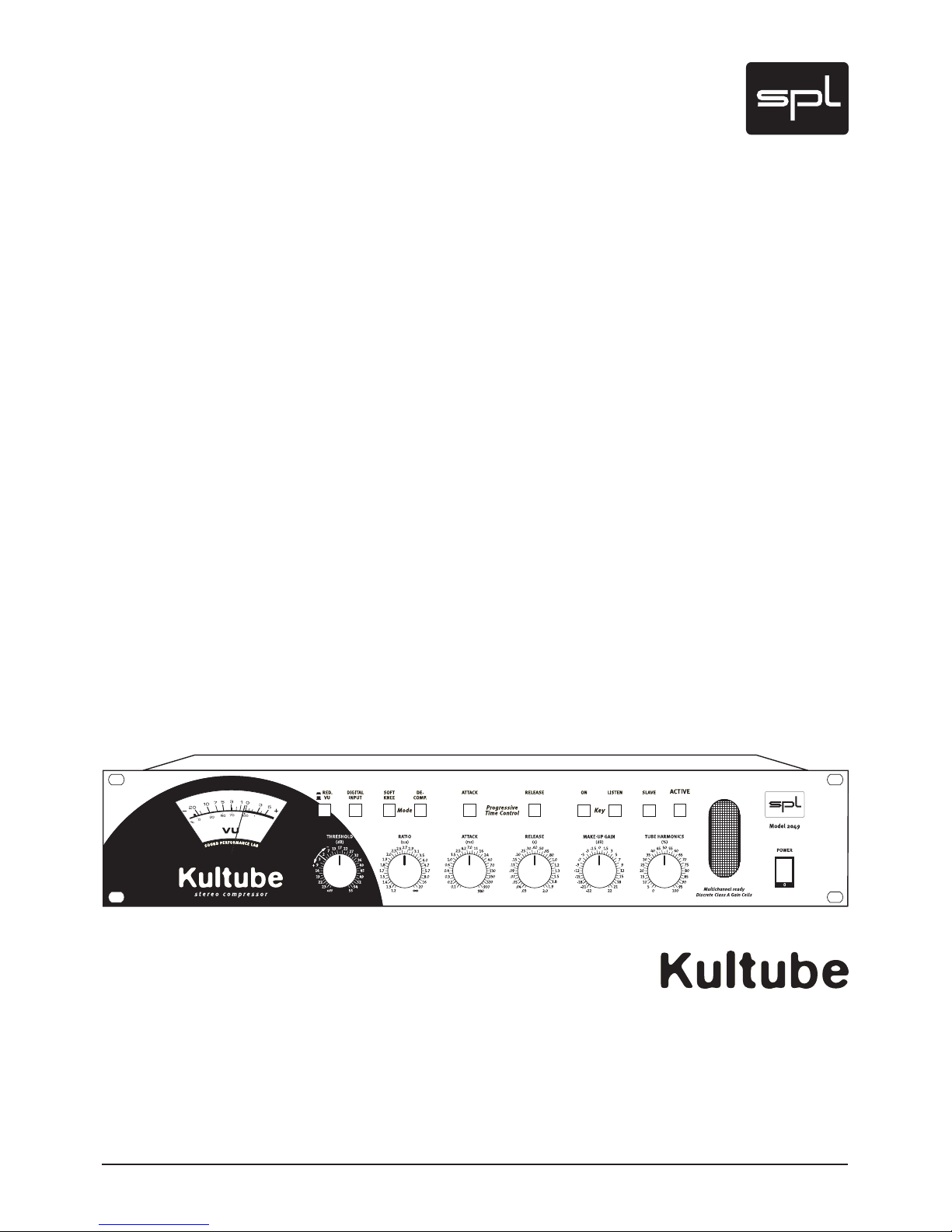
Kultube (Model 2049) Manual
Version 1.2 – 11/2008
R & D: Ruben Tilgner
The information in this document has been carefully verified and is assumed
to be correct. However Sound Performance Lab (SPL) reserves the right to
modify the product described in this manual at any time. Changes without
notice. This document is the property of SPL and may not be copied or repro-
duced in any manner, in part or full without the authorization of SPL.
Limitations of Liability:
In no event will SPL be liable for any damages, including loss of data, lost
profits, cost of cover or other special, incidental, consequential or indirect
damages arising from the use of the unit, however caused and on any theory
of liability. This limitation will apply even if SPL or an authorized dealer has
been advised of the possibility of such damage.
CE Declaration of Conformity
Manufacturer: SPL electronics GmbH
Type of Equipment: Audio Signal Processor
Product: Kultube, Model 2049
Compliance Engineer: Wolfgang Neumann
Test Basis: EN50081-1:1992, EN50082-1:1992, EN60065:1993, EN61000-3-
3:1995, EN60065:2002, EN55013:2001, EN55020:2002, EN61000-3-2:2000,
73/23 EWG; 93/68 EWG.
We herewith declare, that the construction of the Kultube, Model 2049, is in
compliance with the standards and regulations mentioned above.
Notes on environmental protection
At the end of its operating life, this product must not be disposed of
with regular household waste but must be returned to a collection
point for the recycling of electrical and electronic equipment. The
“wheelie bin“ symbol on the product, user‘s manual and packaging
indicates that. The materials can be re-used in accordance with
their markings. Through re-use, recycling of raw materials, or other forms of
recycling of old products, you are making an important contribution to the
protection of our environment. Your local administrative office can advise you
of the responsible waste disposal point.
WEEE Registration: 973 349 88
Sound Performance Lab
SPL electronics GmbH
P.O. Box 12 27
D- 41 368 Niederkruechten, Germany
Phone +49 21 63 98 34 0
Fax +49 21 63 98 34 20
E-Mail: info@soundperformancelab.com
www.soundperformancelab.com
© 2008 SPL electronics GmbH. All rights reserved.

3
Important Security Information ................................................................. 4
Installation, Power Supply ........................................................................ 6
Introduction .............................................................................................. 7
Connections
Rear Panel/Wiring ..................................................................................... 8
General Advices, Sockets & Switches ........................................................ 9
Control Elements
Red. /VU, Digital Input, Softknee, De Comp. ............................................. 11
PTC-Attack, PTC-Release, Key On, Key Listen, Slave, Active ....................... 12
Threshold, Ratio, Release, Make Up Gain .................................................. 13
Tube Harmonics ......................................................................................... 14
Operation – Understanding and enjoying the Kultube
The Threshold Control ............................................................................... 14
The Ratio Control ....................................................................................... 15
The Attack Control ..................................................................................... 16
Progressive Time Control – Attack ............................................................. 17
The Release Control ................................................................................... 18
Progressive Time Control – Release ........................................................... 19
Applications – Using and enjoying the Kultube
Summed Signal Processing ....................................................................... 21
Single Track & Subgroup Processing .......................................................... 21
Side-chain ................................................................................................. 22
Multi Channel and 5.1 Surround Processing ............................................... 23
Specifications ............................................................................................ 24
Guarantee ................................................................................................. 24
Content

4
Please note and retain this manual. Carefully read and follow all of the safety
and operating instructions before you use the machine.
Be doubly careful to follow all warnings and special safety instructions
noted in this manual and on the unit.
Connections: Only use the connections as described. Other connections can
lead to health risks and equipment damage.
Water And Humidity: Do NOT use this machine anywhere near water (for
example near a wash basin or bath, in a damp cellar, near swimming pools,
or the like). In such cases there is an extremely high risk of fatal electrical
shocks!
Insertion Of Foreign Objects Or Fluids: NEVER allow a foreign object through
any of the machine‘s chassis openings. You can easily come into contact with
dangerous voltage or cause a damaging short circuit. NEVER allow any fluids
to be spilled or sprayed on the machine. Such actions can lead to dangerous
electrical shocks or fire!
Opening the Machine: Do NOT open the machine housing, as there is great
risk you will damage the machine, or – even after being disconnected – you
may receive a dangerous electrical shock!
Electrical Power: Run this machine ONLY from sources which can provide
proper power at the prescribed rating. When in doubt about a source, contact
your dealer or a professional electrician. To be sure you have isolated the
machine, do so by disconnecting the power cord from your wall connection.
Be sure that the power cord plug is always accessible. When not using the
machine for a longer period, make sure to unplug it from your wall power
socket.
Power Cord Protection: Make sure that your power cord is arranged to avoid
being stepped on or any kind of crimping and damage related to such event.
Do not allow any equipment or furniture to crimp this power cord.
Power Connection Overloads: Avoid any kind of overload in connections to
wall sockets, extension or splitter power cords. Always keep manufacturer
warnings and instructions in mind. Overloads create fire hazards and risk of
dangerous shocks!
Lightning: Before thunderstorms or other severe weather, disconnect the
machine from wall power (but to avoid life threatening lightning strikes, not
during a storm). Similarly, before any severe weather, disconnect ALL the
power connections of other machines and antenna and phone/network cables
which may be interconnected so that no lightning damage or overload results
from such secondary connections.
Important Security Information

5
Air Circulation: Chassis openings offer ventilation and serve to protect the
machine from overheating. NEVER cover or otherwise close off these open-
ings. NEVER place the machine on a soft surface (carpet, sofa, etc.). Make
sure to provide for a mounting space of 4-5 cm/2 inches when mounting the
machine in racks or cabinets.
Controls And Switches: Operate the controls and switches only as
described in the manual. Incorrect adjustments outside safe para-
meters can lead to damage and unnecessary repair costs. Never use the
switches or level controls to effect excessive or extreme changes.
Repairs: Unplug the machine and immediately contact a qualified techni-
cian when you think repairs are needed – or when moisture or foreign objects
may accidentally have gotten in to the housing, or in cases when the machine
may have fallen and shows any sign of having been damaged. This also
applies to any situation in which the machine has not been subjected to any of
these unusual circumstances but still is not functioning normally or its perfor-
mance is substantially altered.
In cases of damage to the power cord or its plug, first consider turning off the
main circuit breaker before unplugging the power cord.
Replacement/Substitute Parts: Be sure that any service technician uses
original replacement parts or those with identical specifications as the origi-
nals. Incorrectly substituted parts can lead to fire, electrical shock, or other
dangers, including further equipment damage.
Safety Inspection: Be sure always to ask a service technician to conduct a
thorough safety check and ensure that the state of the repaired machine is in
all respects up to factory standards.
Cleaning: In cleaning, do NOT use any solvents, as these can damage the
chassis finish. Use a clean, dry cloth (if necessary, with an acid-free cleaning
oil). Disconnect the machine from your power source before cleaning.
Important Security Information

6
Installation
Power Supply
Be very careful to check that the rear chassis power selection switch is set
to the correct local line voltage position before using the unit (230 V posi-
tion: 220-240 V/50 Hz, 115 V position: 110-120 V/60 Hz)!
When in doubt about a source, contact your dealer or a professional electri-
cian.
Before connecting any equipment make sure that any machine to be
connected is turned off. Follow all safety instructions from page 5.
Place the unit on a level and stable surface. The unit’s enclosure is EMC-safe
and effectively shielded against HF interference. Nonetheless, you should
carefully consider where you place the unit to avoid electrical disturbances.
The unit should be positioned so that you can easily reach it, but there are
other considerations. Try not to place it near heat sources or in direct sunlight,
and avoid exposure to vibrations, dust, heat, cold or moisture. It should also
be kept away from transformers, motors, power amplifiers and digital proces-
sors. Always ensure sufficient air circulation by keeping a distance of 4-5 cm/2
inches to other units and to the sides of the unit.
Built around a toroidal transformer, the power supply has a minimal electro-
magnetic field to avoid hum or mechanical noise.
The power supply‘s output side is filtered by an RC circuit again to extract
noise and hum from the supplied electrical power.
6000 μf capacitors smooth out the positive and negative half waves. An
additional power supply filter is placed before the power switch to eliminate
disturbing interferences.
All signal processing components are supplied with two separate current
regulators to exclude influences from the remaining components.
The 220 v current for the tube stage power is smoothed out with 200 μF and
stabilized precisely by current regulators. The anode current is switched on
after warm up. Both measures ensure a remarkable extension of the tube‘s
lifetime.
The unit‘s supply voltage can be set to 230 V/50 Hz or 115 V/60 Hz. Check
your local power requirements for the appropriate setting. An AC power cord
is included to feed the IEC-spec, 3-prong connector. Transformer, AC cord
and IEC-receptacle are VDE, UL and CSA approved. The main fuse is rated at
315 mA for 230 v and 630 mA for 115 v. Chassis ground and AC ground can be
physically disconnected with the “GND Lift” switch on the rear panel to elimi-
nate hum.

7
Introduction
The Kultube user disposes over a unique range of powerful compression
tools ranging from subtle unobtrusive processing to very obvious ‘effect‘
compressions. Used conventionally or as an effect, in professional recording
or mastering applications, the Kultube combines outstanding audio quality
with the acclaimed musicality and user-friendliness that SPL units stand for.
Applications cover those of a classic compressor for vocals and instruments,
in both mono and stereo, through stereo operation for subgroup processing
to stereo mastering and multi-channel/surround projects.
Progressive Time Control
With the unique Progressive Time Control (PTC) option for attack and release,
time constants can be optimized by unique circuitry that reacts both to the
input signal and to the user settings - for example, fast impulses are inter-
cepted by an attack time as fast as 20 us. PTC can be seen as an interactively
controllable automation which is not based on fix presets but reacts to the
audio material in a musically useful way.
Discrete Gain Cells
SPL has developed discrete, very high performance gain cells that are used
instead of the usual VCAs and the Kultube is the first product to use them.
They ensure the highest level of musicality and clarity in signal processing
and demonstrate significantly improved distortion values over VCAs.
Tube Harmonics
The adjustable tube saturation of the output stages combined with automatic
output level adjustment can produce tube sound effects that range from the
delicate to the raucous whilst a useful de-compressor mode can reanimate
over-compressed material (such as samples).
Master/Slave Mode
In master/slave mode, any number of devices can be controlled from one
master unit.
Features
• Discrete, high performance gain cells instead of industrial VCAs
• Progressive Time Control: interactively controllable automation for Attack
and Release parameters
• Adjustable tube saturation with output level adjustment
• Selectable soft or hard knee characteristics
• Unique de-compression mode
• Large VU meter displays gain reduction or (mono summed) output level
• Side-chain inputs on the front panel
• Slave mode for multi-channel operation

8
Connections Rear Panel/Wiring
Further Kultubes
as slaves in multi-
channel link mode
21
3
Pin wiring XLR Input:
1=GND 2=Hot (+) 3=Cold (-)
12
3
Pin wiring XLR Output:
1 = GND 2 = Hot (+) 3 = Cold (-)
Pin wiring Stereo Jack Connector:
Tip = Hot (+) Ring = Cold (-) Sleeve = GND
Connection to console:
Insert Sends > Analog Inputs
Insert Returns > Analog Outputs
The Kultube can optionally be equipped with a 24 bit/96 kHz converter module
Connector for external
processing units (e. g.
Equalizer)

9
Again, while Kultube‘s housing is EMV safe and protects against HF interfer-
ences, proper placement of the unit is very important. Before connecting the
Kultube or any other equipment turn off all power. Adjust the voltage setting
on the back so that it corresponds with your local electrical power conditions.
The following graph shows the correct wiring for connecting unbalanced
signals to the balanced XLR connectors:
Alternatively unbalanced signals can be connected with mono Jack connec-
tors to the balanced Jack sockets.
Analog XLR and TRS jacks
Symmetrical XLR and TRS jacks are used for analog in- and outputs. An analog
mixing console is generally connected here (Insert Send/Return). Since the
TRS and XLR jacks are wired in parallel, unbalanced operation of the TRS
jack will have the same effect on the XLR jack and vice-versa. The Kultube is
configured for a nominal level of +4dBu and can handle an input level of max.
25 dBu, with max. +23 dBu available on the output. It is recommended to drive
the Kultube with a signal level of between 0 dBu and 12 dBu – this being the
optimum drive range for signal processing in which also the signal-to-noise
ratio is the best.
General Advices Connections
Sockets & Rear Switch Connections
Input Output
balanced unbalanced balanced unbalanced
1=GND
2=hot (+)
3=cold (-)
1
2
3
1
2
3
12
3
12
3

10
Side-chain inputs
This jack is used as a side-chain input for connecting an external audio signal
to control the Kultube (e. g. an equalizer for frequency dependent processing).
It is configured as a stereo TRS jack, with the left channel on the tip and the
right channel on the ring.
Ideally you should use a normal insert cable that combines a stereo TRS plug
(connected to the Kultube) and two mono TRS plugs (connected to the control
device). When using an equalizer you can connect its inputs to the unused
jack inputs on the Kultube. In this way both the equalizer and the Kultube get
the same signal, since the XLR and TRS jacks are wired in parallel.
To use the side-chain input, activate the KEY ON switch on the front panel.
To monitor the signal, activate the KEY LISTEN switch. For other notes on using
the side-chain function, see the section on page 20.
Multi Channel Link
The MULTI CHANNEL LINK jacks can be used to connect multiple Kultube units
for multi-channel operation, so that they can be used together with a master
unit. Before connecting the link cable, determine which is the master unit and
connect the link cable to the MASTER jack. All linked devices are connected
only through the SLAVE jack.
IMPORTANT WARNING: Always define only one master device! Never
connect more than one device through the MASTER jack – otherwise compo-
nents may be destroyed!
After you have made the cable connections, the SLAVE switch on the front
panel of each slave unit must be activated. From now on all functions of all
slave units are controlled by the master.
See page 21 for additional information about multi-channel operation.
Hum? Ground Lift!
Hum can be eliminated with the GROUND LIFT switch on the rear of the
unit (isolates the internal ground from chassis ground). Hum can occur for
example when the Kultube is connected to devices having a different ground
potential.
Hum problems can also be avoided however by consistently installing
balanced wirings. For this reason the GND lift function is by default not acti-
vated.
Connections Sockets & Rear Switch

11
Switches Control Elements
Please note also the information on various controls under „Understanding
and enjoying the Kultube“ starting page 12.
RED/VU
This switch changes the VU meter over to Gain Reduction mode. The indicator
needle then jumps to the 0 dB value and moves to the left with increasing
compression. The scaled values now refer to gain reduction.
If the RED/VU switch is not pressed, the VU meter indicates the output
level.
If neither the RED/VU nor the ACTIVE switch is pressed, the VU meter indi-
cates the input level. In Slave mode gain reduction is controlled by the master
device.
DIGITAL INPUT
The DIGITAL INPUT switch served to select the converted digital signals as an
input source for the Kultube and adds digital in- and outputs, allowing it to be
easily integrated into a digital production chain.
PLEASE NOTE: This switch function only applies to the converter module
2053 which was discontinued in 2005. It does not work with the current AD
converter module 2376.
SOFTKNEE
SOFTKNEE alters the slope of the compressor. Normally the unit operates in
hardknee mode, but pressing the SOFTKNEE switch activates the soft-knee
mode.
SOFTKNEE provides unobtrusive compression results; the greatest possible
loudness however can only be achieved in hard-knee mode. The slope of the
curves is shown on page 13.
DE-COMP:
This switch activates Decompression mode. This mode causes the compressor
to work in reverse: All signals above the preset threshold become louder, and
the Ratio controller determines the intensity of the volume increase. Please
note that the Make-Up controller now works exactly in reverse: the signal
becomes softer when the controller is turned to the right and louder when
turned to the left.

12
Progressive Time Control: ATTACK
This function allows to switch in an adjustable automatization of the time
constants which is set up with the ATTACK control.
Put simply you can now influence the compression intensity for rapid signal
increases, or when the function is turned off determine the time until a certain
compression level is reached.
Progressive Time Control: RELEASE
The release times can also be switched to automatic based on the Release
control: the latter then determines an average value to return the release to.
Use of the Progressive Time Control is especially recommended with complex
summed signals.
KEY ON
KEY ON allows you to use an external signal as the control source for the
compressor.
This signal is brought in to the SIDECHAIN INPUT jack on the rear of the unit.
Now the control activity of the compressor is determined only by the external
signal.
KEY LISTEN
Use the KEY LISTEN switch to monitor the external side-chain signal. This
makes it easy for example to monitor and adjust a connected equalizer.
Whereas the VU meter normally indicates the in- and output level, enabling
KEY LISTEN causes the meter to indicate the side-chain signal. This provides a
quick way to check also whether a signal is present.
SLAVE
This allows you to switch the Kultube to Slave mode so that it can be controlled
from the Master device. All the function except for TUBE HARMONICS are now
controlled by the Master. Both the Master and all the Slave units now get the
same control signal. Also the Slave unit signals are evaluated for analysis.
ACTIVE
The ACTIVE switch turns on the Kultube. If the device is not turned on, the
input signal is fed directly to the output jacks via a relay hard bypass. The
ACTIVE switch thus allows for a quick A/B comparison. When the Kultube
is turned on the LED on the ACTIVE switch flashes to indicate the warm-up
process for the tubes. The unit is ready when the LED no longer flashes.
Control Elements Switches

13
Controls Control Elements
THRESHOLD
The Threshold control determines the compressor threshold value. The value
scale for the THRESHOLD control indicates the level in dBu. Turning fully left
provides no control, and fully right provides compression starting at a level of
approximately –40 dBu.
RATIO
The RATIO control is used to set the ratio between the original signal and the
compressed signal. A ratio of 1:4 means that a level increase of 4 dB on the
input results in an output change of 1 dB. The more the control is turned right,
the more ‘dense’ the sound becomes. Turned fully right the unit works as a
limiter.
ATTACK
The ATTACK control determines the time the compressor needs to achieve a
reduction of 63% at a level jump of 20 dB. When turned fully left this time is
approximately 100 ms, and turned fully right the time is approximately 0.9 s.
When Progressive Time Control is enabled the effect is somewhat different:
now you are determining the degree to which the fast signal jumps are
compressed, whereas the attack time is automatically optimized (adapted).
Progressive Time Control mode is often advantageous, since the attack time
is only as fast as is necessary for the respective signal. The result is consider-
ably unobtrusive and thus more musical compression behavior without unde-
sired side-effects.
RELEASE
The RELEASE control is used to set the time the compressor needs to back off
by 63% to the original value. Turned fully left this time is approximately 30 ms,
or approximately 2 s for fully right. If Progressive Time Control is enabled,
the Release control is used to set the average value to which the automatic
release time is set back. The more the control is turned right, the slower the
averaging. This gives much better results than with the conventional method
of rigid release time control especially with complex musical material.
MAKE UP GAIN
The MAKE UP GAIN controller is used to change the output level within a
range of approximately –22 dB to +22 dB. For compression you thus set the
value that is indicated on the VU meter in GAIN REDUCT MODE. Actuating
the ACTIVE switch makes the volume increase perceptible. With the built-in
digital converter option the MAKE UP GAIN control is also used to set the level
for the converter. In DE-COMP mode the MAKE UP GAIN control works exactly
in reverse: Turning fully CW results in a damping of –22 dB, whereas fully left
results in a gain of +22 dB.

14
TUBE HARMONICS
The TUBE HARMONICS control allows you to drive the tube output stage infi-
nitely variable to desperation: the more the control is turned in, the further
the tube gets into saturation and the more harmonics are produced.
The output level of this stage is automatically adjusted, i.e. it keeps virtu-
ally the same level as the input signal. This allows you to to change the entire
sonic behavior of the tubes with just one control.
Understanding and enjoying the Kultube
In this section we will describe the individual parameters of the Kultube in
greater and use diagrams to enhance your understanding of how and why the
Kultube works.
The Threshold control
This parameter is used to determine at which level (or loudness) the unit
even responds by specifying a corresponding threshold value. Sometimes
you only need to process individual peaks, and at other times you need to
take more drastic action and set the threshold lower.
Fig. 1 shows the curves for various threshold settings. The X-axis repre-
sents the input level, from –50 dBu to +22 dBu. The Y-axis shows the output
level. You can see a definite change where the compressor is starting to work.
Before this point the ratio between the in- and output is exactly the same, so
that for example an input level of –30 dBu will also be present on the output.
In the area where the curve turns sharply the ratio is approximately 1:4. This
means that only a fourth of the dynamic gain is present on the output. A level
jump of 8 dB will be reflected by just 2 dB on the output.
Operation
Control Elements Controls
Fig. 1,
„Threshold Input vs. Output“

15
The Ratio control
As indicated above, this determines the ratio between the in- and output
level above the threshold setting. The preset value specifies how the input
dynamics should behave with respect to the output: a ratio of 1 to 2 means
that only half of the dynamic change will be present on the output. At 10 dB
of dynamics there will only be 5 dB on the output, whereas using a ratio of 1:8
means 10dB becomes just 1.25 dB, etc.
In short, this determines how much dynamics is allowed to remain. If the
compressor is used to process vocals with very large variations in loudness,
you would select a high ratio value (1:5 – 1:10) to produce a well-balanced and
intelligible signal. When processing summed signals on the other hand, very
high settings will be used in part to process only the peaks of the signal. This
means careful setting of the threshold control is very important.
The slope of the compressor curve may be straight with a sudden rise (hard-
knee, Fig. 2), but it may also show a softly curved slope in which compression
begins slowly (soft-knee, Fig. 3).
Operation
Understanding and enjoying the Kultube
Fig. 2,
„Ratio Hardknee“
Fig. 3,
„Ratio Softknee“

16
Operation Understanding and enjoying the Kultube
In the latter case the ratio changes depending on the in0ut signal. As the
preset threshold value is approached the ratio is comparatively small (1:1.5)
and doesn’t reach the preset maximum value until high input levels are
present. The result is much less conspicuous compression, since the process
does not kick in as suddenly as with hard-knee mode. On the other hand,
hard-knee results in greater loudness and density of the program material.
When using the de-compressor the ratio is exactly reversed, i.e. an input
level change of 2dB for example results in an output of 4dB. The printed ratio
values cannot be used here, since they clearly deviate. You should therefore
use the de-compressor with care, since it will always make the signals louder.
Setting of the threshold control should also be done with caution.
The Attack control
Among the most important functions of a compressor is controlling the
time constants. The attack control determines one of these times, namely the
kick-in behavior of the compressor. In general terms this determines the time
starting at which the signal should be reduced. This allows you to specify how
rapid signal jumps are handled.
How this look with a sinus-burst (test signal) is shown in Fig. 4.
Here you can clearly see that the first part of the burst signal is unprocessed
and only responded to when the settings are faster. When attack times are
set very short, the compressor responds to even the most rapid transients,
so that the peaks are captured. With slower settings transients are allowed to
pass untouched – a kind of leveling in which the compressor responds more
to the average level. If you are processing a drum loop for example, changing
the attack time can cause a few transients to be passed through. Changing
the attack control now determines how many transients remain unprocessed.
Using very short values (0.5 ms) allows in part just a half-wave of a signal to
remain unprocessed, whereas medium values (10ms) result in a whole series
of waveforms to be ignored. This type of response is also frequently used to
make transients in a signal more clearly audible.
Fig 4
„Attack Normal“

17
Processed in this way, drums get more self assertion and sound ‚faster’.
The best setting is not always easy to find, since you usually need to find a
compromise. Very fast settings run the risk of producing audible distortions
– especially in the case of low frequencies, since the compressor now tries
to control each waveform rise. The corresponding control signal assumes a
“saw-tooth” form which distorts the audio signal.
To suppress this effect, you would have to again increase the attack
time until the distortions no longer occur. In normal operation the Kultube
attack control works exactly as just described. There is a unique feature of
the Kultube however that greatly expands the compression possibilities by
providing special technologies to achieve optimum results in all situations:
the Progressive Time Control (PTC), which is described in the following.
Progressive Time Control (Attack)
Simply put, the Progressive Time Control (PTC) is an adjustable automatic
process that works as follows.
The usual (rigid) attack control of a compressor functions, as described
above, such that a resistance value can be varied within the controller circuit
to determine the control response time. The main drawback to this, partic-
ularly when it comes to complex musical material, is that the setting only
applies to a moment, but is not ideal for every moment.
Automatic setting of the attack time (in response to the input signal) has
the advantage of making the optimum setting for each moment. For this the
changing of the resistance value that determines the attack times needs to be
automated. A special circuit determines the momentary ideal attack time and
sets the VCF appropriately. These times can vary between 20 μs and 980 ms
and are set in fractions of a second.
This automatic process is thus a guarantee for perfect compression results,
but the PTC in the Kultube goes even a step further: The attack control can be
used to determine the intensity with which fast signal jumps are compressed
in automatic mode. When you change the attack time using PTC, as for
example when processing drum sounds, you can specify the handling of rapid
signal jumps while at the same time ensuring that the attack behavior is
not affected. A drum loop thus retains its original sonic character while still
appearing denser.
Understanding and enjoying the Kultube Operation

18
Fig. 5 shows the control behavior using a sinus burst as an example. In various
settings it is clearly to see that the burst signal remains almost unchanged in
its form; only the intensity changes.
The PTC feature can provide outstanding results not only for percussive
signals but also for many other musical signals (vocals, guitar, bass, horns,
synthesizers, etc.), since compression is used with the greatest efficiency,
is unobtrusive and sounds „natural“. You should feel free to jump right in to
experimenting with the PTC and find out what it can do for you.
The Release control
The Release control is used to determine how long the compressor needs
after a reduction to drop back to the original value. How it works is shown in
Fig. 6.
Here you see the same sinus burst as for the attack diagrams, but just the
last burst-on part is shown. You can clearly see how the times within which
the original is reached change with various settings of the release control.
Operation Understanding and enjoying the Kultube
Fig. 5,
„Attack PTC“
Fig. 6,
„Release Normal“

19
Operation
Understanding and enjoying the Kultube
The release parameter is also for the most part responsible for unobtrusive
compression. This means it is hard to find the perfect setting as with the Attack
control – particularly in the case of complex summed signals a fixed release
time may hardly be usable. As with the attack times you must always find
a compromise: for very fast and short signal peaks (e.g. drums and percus-
sion) you will want to select short release times (100 ms). But this setting is
usually unusable in all other parts of the musical piece, since now every single
dynamic change will be processed – which will quickly sound very rough and
distorted.
By selecting longer release times (1 s), the remaining sections will sound
quieter, but when short, loud peaks occur your music will start pumping. Here
again the PTC will yield better results.
Progressive Time Control (Release)
Here again we are talking about an automatic release that can be influ-
enced by the release control. When PTC release control is activated, the
Kultube calculates an average of the levels that the music signal is providing.
Automatic control of the release time now refers to this average value, so that
while short, loud peaks are handled correspondingly fast, when it comes to
complex material (summed) the system will not respond to each and every
little peak near the average.
Furthermore the PTC allows you to affect the averaging: the faster the
release time in PTC mode, the more signal components are included in the
processing. This means you will want to select rather slower release values
for summed signals, whereas drum processing for example will yield the best
results using fast settings.
How various settings for a drum loop might look is shown in Figs. 7a-c. Line
A represents the control voltage for the discrete gain cell (instead of VCAs),
Line B the rectified musical signal, and C the averaging.
Fig. 7a
A B C

Operation Understanding and enjoying the Kultube
For settings with larger averages the change in the release time is easy to
recognize. With very small values the control voltage for the Gain Cell “sticks”
to the rectified signal and works almost like an envelope follower.
Fig. 8 on the next page shows the various effects of different release time
settings on a sinus burst, although the principle is not as easily seen here.
These changes are most clearly heard in a drum loop with lots of dynamics.
Turned fully left (fast averaging) the drums pump and you get lots of volume,
whereas turned fully right the control is unobtrusive, but you gain less loud-
ness. For summed signals a mid-range setting (0.8 s to 1.5 s) is therefore
recommended. As in the case of attack control with PTC, release control
makes sense not just for sum processing, but can also be used to outstanding
advantage with other signal types such as bass, percussion, effects or that at
least as problematic as widespread signal type “untrained speaker”, while at
the same time greatly simplifying your processing.
Fig. 7b
Fig. 7c
AB C
A B C
20
Table of contents
Other SPL Recording Equipment manuals

SPL
SPL Transient Designer 2715 User manual

SPL
SPL Marc One User manual

SPL
SPL Transient Designer 4Mk2 User manual

SPL
SPL 1211 User manual

SPL
SPL Madicon User manual

SPL
SPL 2Control 2860 User manual

SPL
SPL Vitalizer stereo MK2-T User manual

SPL
SPL Stereo Vitalizer Jack 9530 User manual

SPL
SPL Transient Designer 2880 User manual

SPL
SPL Crossover User manual

SPL
SPL TwinTube 2920 User manual

SPL
SPL Phonitor 2 1530 User manual

SPL
SPL De-Esser 500 Series User manual

SPL
SPL Attacker2980 User manual

SPL
SPL Vitalizer stereo MK2-T User manual

SPL
SPL Madison 1260 User manual

SPL
SPL Frontliner 2800 User manual

SPL
SPL Atmos User manual

SPL
SPL MMC1 User manual

SPL
SPL DynaMaxx 9735 User manual