manuals.online logo
Brands
  1. Home
  2. •
  3. Brands
  4. •
  5. DSPPA
  6. •
  7. Controllers
  8. •
  9. DSPPA WH-25 User manual

DSPPA WH-25 User manual

This manual suits for next models

1

Other DSPPA Controllers manuals

DSPPA PC1021X User manual

DSPPA

DSPPA PC1021X User manual

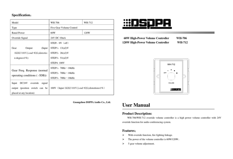
DSPPA WH-706 User manual

DSPPA

DSPPA WH-706 User manual

DSPPA MAG2123S User manual

DSPPA

DSPPA MAG2123S User manual

DSPPA MAG2122E User manual

DSPPA

DSPPA MAG2122E User manual

Popular Controllers manuals by other brands

Sunricher SR-ZV9003T3-RGBW-US Installation

Sunricher

Sunricher SR-ZV9003T3-RGBW-US Installation

Ksenia intro Installation and configuration manual

Ksenia

Ksenia intro Installation and configuration manual

Inovance CAN200 Series manual

Inovance

Inovance CAN200 Series manual

Gauzy LC6 FLEX Controller Installation and operation guide

Gauzy

Gauzy LC6 FLEX Controller Installation and operation guide

Viking SLP-1 Technical practice

Viking

Viking SLP-1 Technical practice

CKD KBX-30E-U Series instruction manual

CKD

CKD KBX-30E-U Series instruction manual

Sharp Energy Sun Flux User manual & installation guide

Sharp Energy

Sharp Energy Sun Flux User manual & installation guide

Yamaha RCX40 user manual

Yamaha

Yamaha RCX40 user manual

AB Quality PowerFlex 400 Frames D-H Service bulletin

AB Quality

AB Quality PowerFlex 400 Frames D-H Service bulletin

Yamaha MJC8 owner's manual

Yamaha

Yamaha MJC8 owner's manual

AL-KO ATC operating instructions

AL-KO

AL-KO ATC operating instructions

Savant SmartControl 2 Deployment guide

Savant

Savant SmartControl 2 Deployment guide

GameSir T3S user manual

GameSir

GameSir T3S user manual

Kostal inveor operating manual

Kostal

Kostal inveor operating manual

Emerson Yarway 20-55 Operating and safety instructions

Emerson

Emerson Yarway 20-55 Operating and safety instructions

CoCo ACM-LV24 Quick installation guide

CoCo

CoCo ACM-LV24 Quick installation guide

Brooks SLA5810/20 Installation and operation manual

Brooks

Brooks SLA5810/20 Installation and operation manual

SIGMA TEK SR 011 Technical manual

SIGMA TEK

SIGMA TEK SR 011 Technical manual

manuals.online logo
manuals.online logoBrands
  • About & Mission
  • Contact us
  • Privacy Policy
  • Terms and Conditions

Copyright 2025 Manuals.Online. All Rights Reserved.

Technical data WH-25 WH-50
Rated power 25W 50W
Component set Rotary switch with stopper, 5 volume levels, 1 off position
Install depth 47mm
Dimension (W*H*D) 70*120*80mm
Specification
WH-25/WH-50 Impedance Matching Stereo Volume Controller
Rated power: 25W/50W
Minimum impedance capability of amplifier: 4-8Ω
Appropriate bridge clip setting (1x, 2x or 4x)
Rotary switch with stopper, 5 volume levels,
1 off position
Rectangle, elegant and compact design
Can run multiple pairs of speakers
Features
WH25/ WH50 is a wall mounted impedance matching stereo volume control, which connects between the speaker
level output of an amplifier, receiver or speaker selector and a pair of speakers.The volume control is designed to
run multiple pairs of speakers without damaging your amplifier or receiver. The adjustment is made by using
bridge clips that can be easily replaced.
Description
Volume control wiring:
CAUTION: Please make sure your amplifier or receiver is turned off before wiring.
This volume control can be used with up to 14-gauge wire.
Measure the distance from the speaker to the amplifier. For distance of 50 feet or less, use
18-gauge speaker wire no more than 1/4” from the end. Loosen the screws on the underside of the
wire block terminal to allow the wire to be pushed completely into the opening, then tighten the
screws to secure the wire. (See Figure #1). If you need to remote the wire, simply loosen the
screws on the undersides of the wire block terminal.
Volume Control
Wiring the Volume Control
Refer to Figure #2 when wiring the volume control:
1.Connect the amplifier or receiver’s left speaker output to the left input terminals on
the removable wire block terminal. Please observe proper polarity of the connections
(+ amplifier to + input on the volume control).
2.Repeat step 1 for the right side.
3.Connect the wires from the left speaker to the left speaker output terminals on the
wire block terminal. Please observe proper polarity of the wires for connect speaker
phases (+ speaker to + output).
4.Repeat step 3 for right speaker connection.
CAUTION: If the input and output connections are reversed, the minimum setting on
the volume control will cause a short across the amplifier or receiver output terminals,
resulting in serious damage to your amplifier or receiver. Please double check steps 1
through 4. This volume control cannot be connected in series with another volume
control.