High power electronics for professional RC racing Advanced Cooling Technology for RC Cars 1/10
________________________________________________________________________________________________________________________________________________
responsible and knowledgeable adult. Keep t is
product away from t e reac of small c ildren.
Do not touc t e device Immediately after using, it
can generate ig temperatures. If t e temperature
of ESC is ig er t an 70°C, t e buttons can be ot.
Please, wait until it cools down to 50°C before you
switc it off by button, or switc t e ESC from t e
battery for switc off.
Stop t e usage immediately once t e temperature of
t e ESC exceeds 130°C, as t is may cause damage to
bot t e ESC and motor. We recommend setting t e
“ESC T ermal Protection” to 130°C (t is refers to t e
internal temperature of t e ESC).
Never leave t e device unsupervised w ile it is
switc ed on, in use or connected wit a power
source. If a defect occurs, it could cause a damage or
fire of t e product or t e surroundings.
Never wrap your product in plastic film, metal foil or
similar, if it is switc ed on.
Never allow t is product to come in contact wit
water, oil, fuels or ot er electroconductive liquids.
Never place t is product near t e source of fire or
very ig temperatures.
Never switc t e device off from t e battery w ile
pressing t e t rottle.
We recommend to use NITRIDE toget er only wit
t e compatible devices listed t e c apter 4. Usage
NITRIDE wit ot er devices was not tested yet and
we are not responsible for any disfunctions or
damages caused by using NITRIDE toget er wit
unaut orized devices.
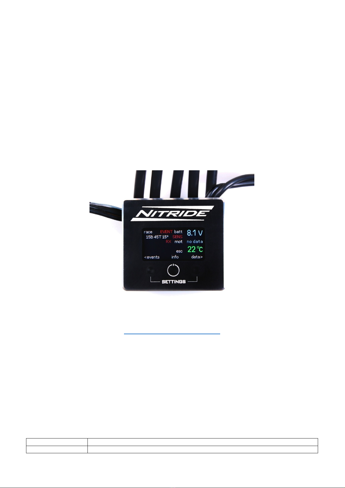
Key Features and Specifications
Developed especially for 1/10t professional RC cars.
TFT LCD color display wit resolution 160 x 80 pixels.
Size: 38,3 (L) x 34,3 (W) x 24,5 (H) mm.
Weig t: 50 g wit out wires / 90 g wit wires AWG13
- 180 mm.
70 % of weig t located in bottom side of ESC.
Power supply: 2S LiPo.
Current cont. / pulsed: 180 A / 1500 A.
BEC: 7,4 V fixed, 4 A cont. / 10 A peak at 125 °C.
Extreme low internal resistance based on silver
conductive layer.
Advanced Cooling Tec nology based on Aluminium
Nitride Ceramic Cooler.
Designed for ig level RC racing.
Zero Timing (Blinky Mode) supported.
For sensored BLDC motors from 4.5T up.
Designed and produced in Czec Republic.
Revolutionary easy Rx calibration.
Realtime monitoring: battery voltage, ESC and motor
temperatures.
Self-diagnostic before t e race: motor temperature,
sensor cable, battery.
Post-race data evaluation.
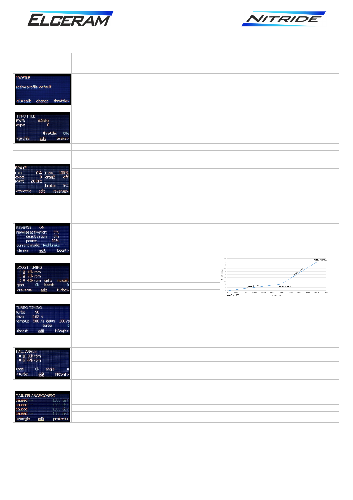
Easy programming: t rottle, brake, boost and turbo
timing, all angle and many ot er functions.
Race data logging, temperature and ot er curves,
istograms and more.
Adjustable maintenance reminder for easy c eck.
No programming interface needed.
We recommend to use NITRIDE toget er only wit t e compatible devices listed below. Usage NITRIDE wit ot er
devices was not tested yet and we are not responsible for any disfunctions or damages caused by using NITRIDE
toget er wit unaut orized devices.