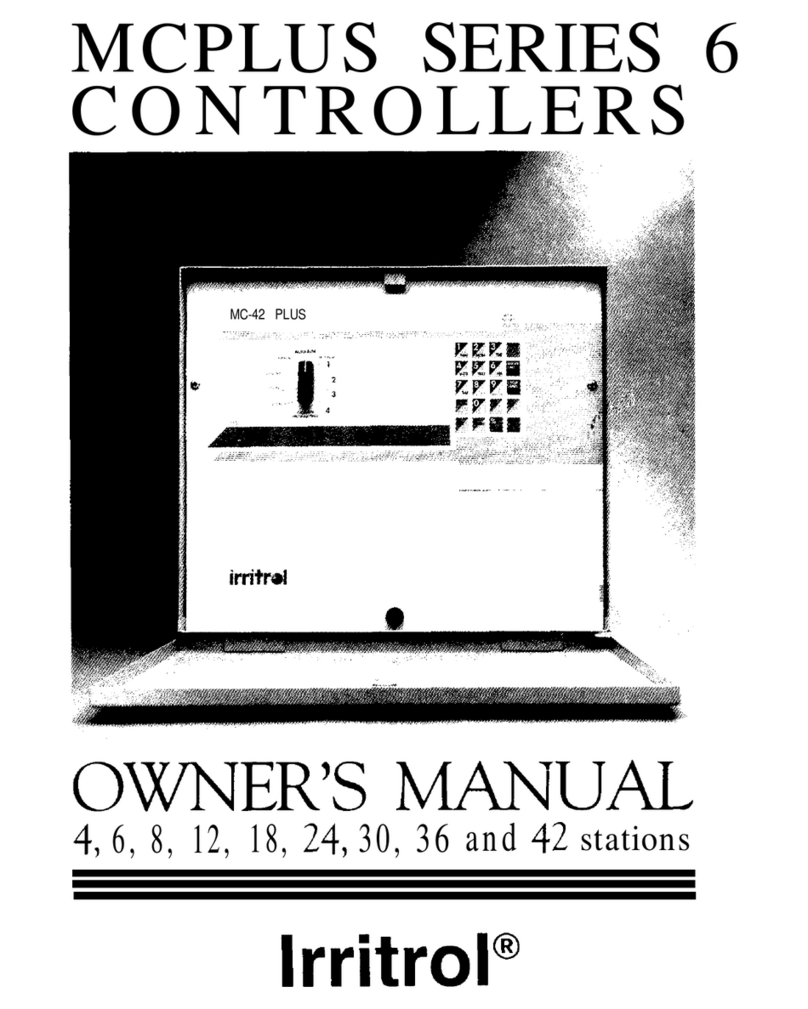
Irritrol Dial Series User manual

DIAL SERIES
CONTROLLERS
OWNER’S
MANUAL
5,
7,
11, 14, 16, 18, 24, 30 and 36 stations
q
lrritrol

TABLE OF
CONTENTS
Table of Features
................................................................
1
Location of Parts
................................................................
.2
Installing and Wiring the Controller
..........................................
.4
Selecting the Site
...........................................................
.4
Mounting the Controller
..................................................
.5
Connecting the Power
.....................................................
.5
Hooking Up the Valves
....................................................
.7
Hooking Up a Pump Start Relay
...........................................
.8
How the Backup System Works
...........................................
.9
Installing and Using Sensor Ports
.........................................
.9
How the Electronic Circuit Breaker Works
..............................I0
Programming the Controller for Watering
..................................
.I1
Developing a Watering Plan
..................................................
.I1
Setting the Current Time and Day
......................................
.12
Erasing Any Prior Programs
..............................................
.I3
Setting the Station Watering Time
......................................
.13
Selecting the Days to Water
..............................................
.I4
Programming Watering Start Times
.....................................
.16
Program B Watering
......................................................
.I7
Manual Operation............................................................
..18
Manual Onn...............................................................
..18
Manual Off
.................................................................
18
Rain Offf
..................................................................
..19
Semi-Automatic Watering
...............................................
.20
Using Advanced Features
....................................................
.2
1
Water Budgeting
..........................................................
,2
1
Option 1: Six-Day Watering Schedule
..................................
.22
Option 2: Programming Water Time in Seconds
.......................
.22
Option 3: Programming Water Time in Hours
.........................
(23
Option 4: Loop Watering
................................................
24
Troubleshooting
...............................................................
.25
Index
...........................................................................
.27
TABLE OF
FEATURES
Thank you for purchasing a Dial Series Controller. Listed below are
some important features you should be aware of before you begin
programming. Details on how to implement these features are described
on the following pages.
Two independent programs that can run concurrently
6
-
or
14-day
calendar
Station watering time in seconds, minutes or hours
Non-volatile memory that retains programmed information
indefinitely
9-volt battery to ensure accurate time during power failures
Water budgeting
Valve test for easy system testing of each station for 1 to 9 minutes
Remote ready for upgrading to an IrriTrolremote control system
Selectable loop option for continuous cycling of program
Electronic circuit breaker that identifies and overrides bad stations
Single-entry “All stations watering time”
Semi-Automatic and true manual operation
Rain off programmable to 7 days
Rain off sensor hook-up
Sensor start hookup in program B for water conservation systems
Start time stacking overlap protection within each program
UL listed
These are just a few of the many features of the Dial Series Controllers.
Please review your manual before beginning programming.
LOCATION OF
PARTS
1.
2.
3.
4.
5.
6.
7.
8.
9.
10.
11.
12.
13.
14.
15.
16.
17.
18.
19.
20.
21.
22.
23.
24.
25.
Function Dial:
For selecting programming and operating functions
Water Budget:
For single-entry increase or decrease of watering times for all
stations within a program by a selected percentage (does not alter program)
Program Erase: For erasing programmed information
Options: For selecting additional features, 6-day watering schedule, seconds,
loop and/or hours
Valve Test: For running a valve test for all stations from 1 to 9 minutes
Rain
Off: For turning off output to all stations manually or programmable to
7 days off
Manual: For true manual operation
Semi-Automatic Watering: For activating a manual watering cycle that uses
the programmed station watering times
Auto Run: Position for automatic operation
Advance Buttons: For programming and operating functions
Digital Display: For viewing time and program information
On/Off Buttons: For programming and operating functions
Program Select Switch: For program selection
Program LEDs: To indicate what program is currently operating
Water Budget Indicator:
Shows whether water budgeting for the program
selected is other than 100%
Current Time: For setting current time
Current Day: For setting calendar day
Station Watering Time: For setting individual watering time for each station
All Station Watering Time: For setting watering-time for all stations with
one entry
Watering Day Schedule: For setting which days to water
Watering Start Times: For setting the times each watering cycle will start
Terminal Strip: For hook-up of transformer, valve wires, common wire,
pump start and sensors
Battery Snap: For hookup of 9V alkaline battery to keep time during
power failures
12OV/24V transformer
Short Wire:
Must be installed if sensor is not used
16
17
18

INSTALLING AND WIRING
THE CONTROLLER
-
CONTINUED
This section includes instructions for installing the controller and
hooking up the electricity. To ensure safe operation, it is important to
follow the instructions carefully. The following topics are covered:
l Selecting the site
l Mounting the controller
l Connecting the power
l
Hooking up the valves
-Testing the valve hook-ups
l
Hooking up a pump start relay
l
How the backup system works
l
Installing and using sensor ports
l
How the electronic circuit breaker works
CAUTION:
To avoid injury to you or damage to the controller,
you MUST follow the sequence of installation steps
outlined in this manual.
SELECTING THE SITE
The controller comes in an outdoor, rain-resistant, rust-resistant and
dust-resistant box. Selecting the correct location for your controller is
essential to ensure safe operation. Select a site for the controller that is:
1.
Away from direct sprinkler spray.
2.
In a shaded and dry location, if possible. Avoid direct sun; do not
expose to temperatures exceeding 130°F.
3. NOT in a closed and humid environment, or where it is subject to
continual heavy condensation.
4. Accessible to a
3-wire,
grounded 120-volt AC, 60 Hz power supply.
4
Installing
&
Wiring the Controller
MOUNTING THE CONTROLLER
WALL MOUNT: For wall mounting, install the controller vertically
on a flat, secure surface. Use the enclosed template to locate mounting
screw holes. Follow complete mounting instructions on template.
PEDESTAL: For free-standing installation on a pedestal, follow the
installation instructions in the pedestal box.
CONNECTING THE POWER
The controller is a solid-state microcomputer that may be affected by
transient surges and electromagnetic interference. Wherever possible,
the controller should be installed on its own dedicated circuit breaker.
CAUTION:
Be
sure to follow all applicable local electrical
wiring codes.
CAUTION: DO NOT install the controller on the same line or
within 15 feet of a heavy inductive load, such as a
pump, motor, air conditioner, refrigerator, trans-
former, etc. Valve and power wires must also be
routed away from “high power users.”
CAUTION:
DO NOT turn on the power until all valves are
wired (see “Hooking Up the Valves,” page 7).
1.
Remove the lower panel by unfastening the screw located in the
middle of the panel and lifting the panel out and down.
2.
Verify that th
e
yellow and red wires of the transformer are connected
to the
24-volt
AC input on the terminals of the controller (see
figure
1,
page 6). Connect the black and white wires of the 120 volt
AC, 60 Hz power supply to the black and white wires of the trans-
former (see figure 1).
CAUTION: DO NOT wire 120 volts directly to the PC board
terminals; the transformer supplied with the control-
ler MUST be used.
Installing
&
Wiring the Controller
5

-
CONTINUED
Figure
1.
Electrical
Hook-ups
3.
Connect the green ground wire directly to the terminal
labeled “GND.”
In areas where lightning is prevalent or the condition of the third wire
ground is questionable, a ground rod must be installed. Connect the
grounding rod to the controller’s case ground using a
#10
gauge or
heavier stranded copper wire.
The distance from the controller’s case to the earth ground should
be minimized.
-
CONTINUED
HOOKING
UP THE VALVES
A maximum of 20 VA (0.8 amps) may be output on each station.
A maximum of 36 VA( 1.5 amps) may be programmed to operate
simultaneously (including master valve).
1.
Strip the solenoid wires approximately
l/2
inch (do not bend
exposed end).
2.
Following the wiring diagram in figure
1,
insert straight bare wire
between the plates of the “sure grip” terminal. Connect one solenoid
wire to the station terminal and the other to common. Tighten screws
firmly.
CAUTION: Use a separate (dedicated) valve common wire for
each controller. DO NOT daisy-chain controllers
together using the same common wire.
3.
Before turning on the power, recheck all leads connected to the
terminal block for shorts.
TESTING THE VALVE HOOK-UPS
CAUTION: NEVER short wires in order to identify a station or
to verify power from
24-volt
side of transformer.
This will result in damage to controller and/or
transformer.
1.
Make sure the valve common wire and all station wires are connected.
2.
Turn on power to the controller.
3.
Turn dial to Valve Test position.
4.
Press Advance A or Advance
v
to change the test time from 1 min.
to 9 min.If time is not changed, 2 min. will be assumed.
5.
Press the On A key.
Each station in sequence will turn on for the number of minutes you
selected. A short circuit test will occur during the valve test. If a short
circuit condition exists on any station, the controller will display
“FUSE” alternately with the station number or zero (0) for the master
valve. “FUSE” indicates a short on that station.
NOTE:
Any operating program cycles will be paused during a
valve test cycle.
6
InstalIing
&
Wiring the Controller Installing
&
Wiring the Controller
7

-
CONTINUED
-
CONTINUED
HOOKING UP A PUMP
STARTRELAY
In cases where a pump is to be controlled by the master valve output,
DO NOT drive the pump directly from the controller. The master
station must be connected to the coil of a 24-volt AC relay, such as an
Essex
#184-20105-101Z
(IrriTrol
part number I 1001).
HOW THE BACKUP
SYSTEM WORKS
The controller is equipped with non-volatile memory for retention of
programmed information. Once programming is complete, the control-
ler will retain your program in the event of a power failure. There will be
no need to reprogram following a power failure.
CAUTION: Connecting a pump to the controller without a
24-volt
AC relay will damage the controller.
The pump latch relay should be set up by an electrician so that a switch
closure will activate the latch relay coil, turning on the pump. The
switch contacts of the relav should be connected to control the latch
relay coil (see figure 2). The relay should be mounted at least 5 feet from
the controller box, and the box MUST be grounded. Installation must
follow all local electrical wiring codes.
This controller is also equipped with a timekeeping circuit. This allows
the controller to maintain accurate time during a power failure for up to
30 days continuous via a standard
9-volt
alkaline battery (not included).
NOTE:
The controller will not activate valves during
a power failure.
INSTALLING AND USING
SENSOR PORTS
CAUTION: DO NOT attempt to power the controller using
power from one phase of pump power. This can
seriously damage the controller.
The controller is equipped with two types of sensor hookups.
1.
Rain Off Sensor Hook-up: Terminals labeled “Inhibit Sensor” on the
controller’s terminal block. When the sensor contacts open, the
controller will inhibit output to all stations (all programs are affected).
If no sensor is
used, the “short” wire must be installed.
Start Sensor Hook-up: Terminals labeled “Start Sensor” on the
controller’s terminal block. The sensor must be a “normally open” type
of sensor. When the sensor contacts close, the controller will start a
Program B watering cycle.
2.
J2
This sensor hook-up enables you to activate watering using a sensor,
such as a moisture sensor. Sensor contacts must remain closed for 30
seconds before the cycle will start.
If the sensor remains closed after completion of the watering cycle,
another cycle will be initiated. If the sensor opens before completion
of the watering cycle, no new cycle will be initiated. The cycle in
progress, however, will continue watering until completion.
POWER
I0
install a sensor:
Figure 2.
Installing
a Relay for a Pump
1.
Attach the sensor to the terminals of the controller’s terminal block.
Adjust the sensor according to manufacturer’s instructions.
8
Installing
&
Wiring the Controller
Installing
&
Wiring the Controller
9

-
CONTINUED
HOW THE ELECTRONIC CIRCUIT
BREAKER WORKS
The controller is equipped with an electronic circuit breaker.If the
controller detects a short circuit, the shorted station (valve) will be
turned off automatically. The display will then alternately flash “FUSE”
and the shorted station number or
"0"
for the master valve. The
controller will continue to automatically water the other stations and
the following watering cycles until the short is repaired.
Common conditions of the electronic circuit breaker include:
CONDITION:
Diagnosis:
Solution:
Diagnosis:
Solution:
Diagnosis:
Solution:
CONDITION:
Diagnosis:
Solution:
Diagnosis:
Solution:
CONDITION:
Diagnosis:
Solution:
“FUSE” and one or more station numbers
alternately flash.
One or more stations are shorted.
Check station(s) for cause of shorted condition. Repair valve(s)
and/or wiring on station(s), and press both Advance buttons at
the same time to clear.
Too many valves are operating at the same time.
Check programs and stations, including master valve for VA
output. Maximum total output is 36 VA (1.5 amps). Reduce
number of valves on at the same time to below maximum output
allowance. Press both Advance buttons at the same time to clear.
A short circuit has occurred with a time duration too short for the
controller to determine the station.
Check valve wiring for breaks in the insulation which may cause
a station output to short to common. Press both Advance buttons
at the same time to clear.
“FUSE” displays without any station numbers.
A transient surge has spiked the line.
Press both Advance buttons at the same time to clear.
An overload or short has occurred while the controller is being
activated by a remote control device such as the RVC system.
Press both Advance buttons at the same time to clear.
“FUSE” is alternately displayed with “0” and none of the
stations is operating automatically.
The master valve is shorted. When this occurs, all station outputs
will be suspended until the short is repaired.
Repair master valve, pump start relay and/or wiring, and press
both Advance buttons at the same time to clear.
PROGRAMMING THE
CONTROLLER FOR
WATERING
To set up a regular watering schedule, follow the steps below. This
section covers the following topics:
l
Developing a watering plan
l
Setting the current time and day
l
Erasing any prior programs
l
Setting the station watering time
l
Selecting the days to water
l
Programming watering start times
l
Program B watering
DEVELOPING A WATERING PLAN
Two watering programs are available. Each program can be used for
separate watering requirements. For example, you might use one
program to water the lawn on Wednesdays and Saturdays, and another
program to water trees and shrubs once a week.
The controller is pre-programmed with a 14-day calendar. The calendar
can be changed to a 6-day calendar (see the Advanced Features section,
page 21). The examples in this section assume a
14-day
calendar.
WHAT
IS A WATERING CYCLE?
Each watering cycle waters all the stations in a program in sequence.
For example, in the sample watering plan shown below, program A has
three watering cycles. Therefore, all four stations in the program are
watered three times each day, first starting at 2
A
.
M
.,
then at 6
A
.
M
.,
and
again at 5 P.M. Before you program a watering schedule, decide how to
use each program.
SAMPLE WATERING PLAN
Program Days Cycle Start Times Stations Water Time Duration
A
Every
2 A.M.
10 min.
6 A.M.
:
15
min.
5 P.M.
:
35 min.
5 min.
B
M, once
7~06
A.M.
5
4.5 hrs.
everv
2 weeks
10
Installing
&
Wiring the Controller

-
CONTINUED
-
CONTINUED
Number of Watering Cycles Available
Programs
A and B can have up to 3 watering cycles each. For example,
program A in the sample has three watering cycles. The first starts at
2
A
.
M
.,
the second at 6
A
.
M
.,
the third at 5
P
.
M
.
Therefore, each station in
program A is activated three times each day.
Overlap Protection
The
start time stacking feature on this controller provides start time
overlap protection in the event that an error in programming or an
increased water budgeting percent creates an overlap between cycle start
times. If an overlap occurs, the controller will automatically suspend
the start time until the current watering cycle finishes.
SETTING THE CURRENT
TIME AND DAY
Before you can program the controller for watering, set the current time
and day of the week. This information is used to control the watering
schedules. Once set, the time and day apply to all programs. To set the
day and time, follow the steps below. To change the day or time, use the
same steps.
CURRENT TIME
1.
Set the dial to the Current Time position.
2.
Use the On A and
Off
V
buttons to increase or decrease the time
shown in the digital display.
3.
For
P.M.,
make sure the p.m. indicator
(‘)
is displayed.
NOTE: Midnight is 12:00
A
.
M
.;
noon is
12:00 P.M.
CURRENT DAY
1.
Set the dial to the Current Day position.
The controller displays a number corresponding to the current day.
1=Sun,
2=Mon,
3=Tues,
4=Wed,
5=Thur,
6=Fri,
7=Sat,
8=Sun
(2nd week), etc., up to 14.
2.
Press the
Advance A or Advance
V
buttons until the number
corresponding to the current day appears in the display.
Programming
the
Controller for Watering
ERASING ANY PRIOR PROGRAMS
This process erases all watering times, watering start times, the watering
day schedule and resets water budget to 100%.
To clear prior watering programs:
1.
Turn the dial to the Program Erase position.
2.
Press the both
Advance
buttons at the same time.
The controller display flashes “PE,” indicating that the existing
program(s) have been erased. Both programs are erased regardless of
program switch position.
NOTE:
Program Erase does not change option settings and does
not erase current time and day information.
SETTING THE STATION
WATERING TIME
Follow the steps below to program how long each station will water.
1.
Make sure the program switch is set to the desired program, A or B.
2.
Set the dial to the Station Watering Time position.
The controller displays the station number on the left and the station
watering time on the right. For example, the display
"1:10"
indicates
station one is set to water for 10 minutes.
3.
Use the Advance A or Advance
V
buttons to select the desired
station number.
4.
Press the On A button to increase watering time, the Off
V
button
to decrease watering time.
NOTE:
To skip a station, set watering time to zero (0).
5. Repeat steps 3 and 4 for each station.
NOTE:
The start time stacking feature on this controller provides
start time overlap protection in the event that an error in
programming or an increased water budgeting percent
creates an overlap between cycle start times. If an overlap
occurs, the controller will automatically suspend the start
time until the current watering cycle finishes.
Programming
the
Controller for
Watering
13

14
-
CONTINUED
SETTING THE SAME WATERING TIME
FOR ALL STATIONS
Use this feature to set the same watering time for all stations using a
single entry. This feature applies to all stations within the same program.
1.
Select the desired program, A or B.
2.
Set the dial to the All Stations Watering Time position.
3.
Press the On A button to increase watering time, the Off
V
button to
decrease watering time.
4.
Press both Advance buttons at the same time to
enter. The
display will
flash to indicate the entry was accepted.
DELETING A PROGRAMMED STATION
To delete a programmed station, set watering time to zero (0)
SELECTING THE DAYS TO WATER
The Dial Series controller has a 14-day watering schedule
(6-day schedule instructions are listed in Advanced Features,
page 21). Table 1 below shows the numbers corresponding to the
days of the week. To program the watering days, refer to table 1
and the steps below.
Table
1.
Watering
Days Schedule
SUN MON TUE WED THU FRI
SAT
1st Week:
1
23
4
5
6
7
2nd Week:
89
10
11
12 13
14
-
CONTINUED
1.
Select the desired program, A or B.
2.
Set the dial to the Watering Day Schedule position.
3.
Press the Advance A or Advance
V
buttons until the desired day of
the week is displayed.
4.
Press the On A button to schedule a day on, the Off
V
button to
schedule a day off.
DISPLAYING PROGRAMMED WATERING DAYS
To display the watering days without changing them, do the following:
1.
Select the desired program, A or B.
2.
Set the dial to the Watering Day Schedule position.
3.
Press the Advance A or Advance
V
buttons repeatedly.
The controller displays the days on and days off. For example, the
display “1:ON” indicates Sunday of the first week is a scheduled day
on; “8:OF’ indicates Sunday of 2nd week is not a watering day.
NOTE: OF = OFF.
DELETING A PROGRAMMED
WATERING DAY
If you make a mistake or want to delete a programmed day on, do the
following:
1.
Set the program switch to the program with the day to be deleted,
A or B.
2.
Press the Advance A or Advance
V
buttons until the desired day of
the week is displayed.
3.
Press the Off
V
button to schedule a day off.
4.
Repeat for all watering days to be deleted.
Programming
the Controller for Watering
15

16
-
CONTINUED
PROGRAMMING WATERING
START TIMES
Use this feature to set the time for watering to start on the scheduled
watering days. Three watering start times per day are available in each
program; use start times 2 and 3 to water more than once per day.
1.
Select the desired program, A or B.
2.
Set the dial to the Watering Start Times, position 1.
3.
Press the On A button or the Off
V
button to select the start time.
4. Make sure the p.m. indicator
(‘)
is displayed if watering start time is in
the p.m. period.
WATERING MORE THAN ONCE A DAY
1.
Select the desired program, A or B.
2.
Set the dial to the Watering Start Times, position 2 or 3.
3.
Press the
On A
button or the Off
V
button to select the start time.
4. Make sure the p.m. indicator
(‘)
is displayed if watering start time is in
the
P.M.
period.
NOTE:
The start time stacking feature on this controller provides
start time overlap protection in the event that an error in
programming or an increased water budgeting percent
creates an overlap between cycle start times. If an overlap
occurs, the controller will automatically suspend the start
time until the current watering cycle finishes.
DISPLAYING WATERING START TIMES
1.
Select the desired program, A or B.
2.
Set the dial to the Watering Start Times, position
I,2
or 3.
The controller displays the programmed watering start times.
Programming the Controller for Watering
-
CONTINUED
CANCELLING A WATERING START TIME
1.
Select the desired program, A or B.
2.
Set the dial to the Watering Start Times, position
1,2
or 3.
3.
Press the On A button or the Off
V
button to select a start time
of zero
(0:00).
NOTE:
Zero time is between 1159
P.M.
and 12:00
A
.
M
.
PROGRAM B WATERING
Use program B to establish a different watering schedule, with different
stations and watering times than in program A. Programming is the
same except that the program switch is set to B.
EXAMPLE: You have programmed stations 1,2 and 3 in program
A to water 10 minutes every day, starting at
6:00
A
.
M
.
Suppose you want to add a fourth station that waters
once a week on Wednesday at
7:00
P.M.
for 30 minutes.
You would need to program station
4
on program B.
To program station 4 to water for 30 minutes, starting Wednesday
at 7:oo
P.M.:
1.
Set the switch to
program
B.
2.
Follow the programming instructions for “Setting the Station Water-
ing Time.” For station 4, select 30 minutes.
3. Follow the programming instructions for “Selecting the Days to
Water.” To select Wednesdays, select day 4 (for the 1st week) and day
11 (for the second week).
4. Follow the programming instructions for “Programming Watering
Start Times.” Select
7:00
p.m. for the start time.
NOTE:
In this example, station 4 is the only station with a
watering time; therefore, it will be the only station
operating in program B.
NOTE:
You may water up to six times per day with station
watering time in both programs, or use Option 4, Loop
Operation (page 24), for unlimited start times.
Programming the Controller for Watering
17

-
18
MANUAL OPERATION
Manual operation allows you to perform a one-time watering function
without affecting the programmed watering plan. For example, you
might want to turn off sprinklers on a rainy day but have watering
resume normally after that. This section includes instructions for the
following manual operations:
RAIN
OFF
Use this feature to temporarily turn off watering, such as when it is
raining. As long as this feature is on, watering cycles cannot be activated
automatically.
l Manual on and off
1.
Set the dial to the Rain Off position.
l Rain off Stations currently watering will turn off after a 2-second delay.
l Semi-automatic watering To return controller to normal operation, turn dial to Auto Run
position.
MANUAL ON
Use this feature to water one station for any amount of time regardless of
programming.
1.
Set the dial to the Manual position.
2.
Use the Advance A or Advance
V
buttons to select
the station number.
3.
Press the On A button.
The station will water until turned off or until midnight, whichever
comes first.
TURNING OFF MANUAL WATERING
1.
Press the Off
V
button, or move the dial out of Manual position.
MANUAL
OFF
Use this feature to turn shut off a station that is currently watering.
To turn off a manually “On” station:
1.
Set the program switch to the desired program, A or B.
2.
Set the dial to the Semi-Automatic position.
3.
Press the Off
V
button.
To turn off output to all stations:
1.
Set the dial to the Rain
Off
position.
I
-
CONTINUED
I
PROGRAMMABLE RAIN OFF
Use his feature to turn off watering cycles for a specific length of time,
from 1 to 7 days.
1.
Set the dial to the Rain
Off
position.
2.
Press the On A or Off
V
buttons to select number of days to turn off
(from 1 to 7).
3.
Return dial to Auto Run position.
In the Auto Run position, the display shows the number of days off and
counts down. For example, “OFF7” = 7 days off; tomorrow will display
“OFF6.”
TO CANCEL PROGRAMMABLE RAIN OFF
1.
Set dial to the Rain
Off
position.
2.
Press the On A or Off
V
buttons until display reads “OFF’
(no number).
3.
Return dial to Auto Run position.
1C-l
Manual
Operation
17

-
CONTINUED
SEMI-AUTOMATIC
WATERING
Use this feature to activate a given station and all subsequent stations in
a program.
Only
stations with watering times in the selected program
will be watered.
1.
2.
3.
4.
5.
Set
the program switch to the desired program, A or B.
Set the dial to the Semi-Automatic Watering position.
Use the Advance A or Advance
V
buttons to select the station you
intend to turn on.
Press the On A button to start the watering sequence.
Return the dial to the Auto Run position.
NOTE:
All stations programmed after the selected starting station
will‘tum on automatically in sequence.
NOTE:
The controller will return to automatic programmed
watering at the end of the semi-automatic watering cycle.
20
Manual
Operation
USING ADVANCED
FEATURES
The Dial Series controller offers several advanced features for
sophisti-
cated
watering applications. These advanced features include:
Water budgeting (programs A
&
B)
Option 1: Six-day watering schedule (programs A
&
B)
Option 2: Programming water time in seconds (program B only)
Option 3: Programming water time in hours (program B only)
Option 4: Loop operation (program B only)
WATER BUDGETING
The water budgeting feature allows you to quickly increase or
decrease the watering time per program. The currently programmed
times can be adjusted by a percentage ranging from 0% through 255%.
For example, in the winter you might want to water only 50% of the
programmed time.
To use water budgeting:
1.
Select the desired program, A or B.
2.
Turn the dial to the Water Budgeting position.
The controller displays the current water budgeting percent, such as
"100"
for 100%.
3.
Press the On A or Off
V
buttons to select the watering percent, such
as
"150"
to increase watering by
50%,
or
"50"
to decrease by 50%.
NOTE:
Watering run times may be returned to their original values
by setting to 100%.
NOTE:
Watering times will be displayed as originally programmed.
NOTE:
For percentages other than
100%
a period will appear in
the lower right side of display. This is to alert the user of a
water budget status in that program.
NOTE:
The start time stacking feature on this controller provides
start time overlap protection in the event that an error in
programming or an increased water budgeting percent
creates an overlap between cycle start times. If an overlap
occurs, the controller will automatically suspend the start
time until the current watering cycle finishes.
21

22
-
CONTINUED
OPTION l:
SIX-DAY
WATERING SCHEDULE
To give you greater flexibility, the watering calendar may be changed
from its factory setting of 14 days to 6 days. This change affects both
programs A and B. This feature provides for watering every day, every
other day, every third day, or every sixth day.
1.
Set the dial to the Options position.
2.
Use the
Advance A or Advance
V
buttons to select option
1.
3.
Press the On A button.
To return to a 14-day schedule:
1.
Set the dial to the Options position.
2.
Use the
Advance A or Advance
V
buttons to select option 1.
3.
Press the Off
V
button.
OPTION 2:
PROGRAMMING
WATER TIME IN SECONDS
This feature changes all stations’ watering times in program B to
seconds. The watering time duration is from 0.1 minute to 9.9 minutes
in 0.1 -minute (6-second) increments.
1.
Set the dial to the Options position.
2.
Use the Advance A or
Advance
V
buttons to select option
2.
3.
Press the On A button.
To return to minutes mode (1 min. to 99 mm):
I. Set the dial to the Options position.
2.
Use the Advance
A
or
Advance
V
buttons to select option 2.
3.
Press the Off
V
button.
Using Advanced Features
-
CONTINUED
OPTION 3:
PROGRAMMING
WATER TIME IN HOURS
This feature changes all stations’ watering times in program B to hours.
The watering time duration is from 0.1 hour to 9.9 hours in 0.1 -hour
(6-minute) increments.
1.
Set the dial to the Options position.
2.
Use the
Advance
A
or
Advance
V
buttons to select option 3.
3.
Press the On
A
button.
To return to minutes mode (1 min. to 99 min.):
1.
Set the dial to the Options position.
2.
Use the Advance
A
or
Advance
V
buttons to select option 3.
3.
Press the Off
‘I
button.
NOTE:
The controller will not allow you to activate both
seconds (option 2) and hours (option 3) at the same
time.If one of these options is “ON” and another is
selected as “ON,” the first option will be turned off
automatically. For example, if option 2 has been selected
as “ON” and option 3 is then selected as “ON,” option 2
will be turned off.

-
CONTINUED
OPTION 4:
LOOP OPERATION
This feature allows you to repeat the watering cycle for a specified
length of time. Using this option allows you to have unlimited start
times. When on, it changes watering start times 1 and 2 of program B to
Loop Start and Loop Stop times. Watering start time 3 will remain as a
normal start.
To program the loop cycle:
1.
2.
3.
4.
5.
6.
7.
8.
Set the dial to the Options position.
Use the Advance A or Advance
v
buttons to select option 4.
Press the On A button.
Select program B.
Set the dial to Watering Starr Time 1 (loop start time).
Press the On A button or the Off
v
button to select the loop
start time.
Set the dial to Watering Starr Time 2 (loop stop time).
Press the On A button or the Off
v
button to select the loop
stop time.
PROGRAMMING A LOOP DELAY
Use station 88 to program a delay during loop watering. This special
station creates a delay between loop cycles with the master valve off for
the amount of time you program.
1.
Select option 4 “ON” (instructions above.)
2.
Make sure the program switch is in the Program B position.
3.
Set the dial to the Station Watering Time position.
4.
Use the Advance A or Advance
v
buttons to select station 88.
5.
Press the On A button or the Off
v
button to select the delay time (0
minutes to 99 minutes).
NOTE: Station 88 is always in minutes regardless of option
2 and 3 settings.
24
Using Advanced Features
TROUBLESHOOTING
Q
Error Solution..
.
0
All Valves Will 1. Verify program: station watering time,
Not Turn on watering start times, watering days schedule,
Automatically current time, current day, and water budget.
2.
Check valve common wire for proper
hook-up.
3.
Check for a fused station; refer to Controller
Displays “Fuse” troubleshooting.
c*
Cannot
Program 1. Remove battery (check voltage).
Disconnect power to controller for 5 min.
Reconnect power and reprogram.
Reconnect good 9-volt alkaline battery.
0
Controller
Skips a Cycle
1.
Verify watering start times and current time.
9 No Display
1.
Check incoming power and valve wiring.
2. Remove batteries (check voltage).
Disconnect power to controller for 5 min.
Reconnect power and reprogram.
Reconnect good 9-volt alkaline battery.
l
a
Valve Stays On
I.
Disconnect valve; check for manual
bleed closure.
2.
Disconnect valve wire to valve. If still on,
valve is bad.
3. Check for manual mode; place controller
in Auto Run mode.
4.
Check solenoids for obstructions or
wiring shorts.
5. Check station watering times, option
settings and water budget percentage.
6.
Check valve for rocks or other obstructions
or torn diaphragm.
25

26 Troubleshooting
-
CONTINUED
+3
Error
Solution..
.
+
Valve Will Not
1.
Make sure dial is not in the Rain Off
Turn On
position and is not in the programmed
Rain
Off
mode.
2. Make sure common wire and valve wire
are correctly connected.
3. Verify the program: station watering
time, watering start times, watering days
schedule, current time, current day,
and water budget.
4. Check solenoid.
5. Check valve bleed tube.
6.Check for a fused station; refer to Controller
Displays “Fuse” troubleshooting. See also,
“How the Electronic Circuit Breaker
Works,” page 9.
*:*
Controller
Displays
“FUSE”
1.
Note station numbers flashing. (Zero (0) is
the master valve.)
2. Examine wiring connections for breaks or
bad connections. Repair and reconnect.
3. Examine solenoid for shorted connections.
Repaired and reconnect.
4.Make sure solenoid rating does not exceed
capacity of controller.
5.Press both Advance buttons at the same
time to reset.
&
Controller
1. Indicates hardware failure. Disconnect
Displays “Err
1”
power for
5
minutes. If “Err” is still
or “Err 2”
displayed, return for repair.
INDEX
Advance Buttons
..........
..........................................................
.2,
10
Advanced Features, Using
.............................................................
.2
1
All Stations Watering Time
........................................................
.2,
14
Auto Run
..................................................................................
.2
Backup System, How It Works
.......................................................
.9
Battery
9-volt Alkaline
.......................................................................
.9
Snap
....................................................................................
.2
Budgeting, Water
........................................................................
.2
1
Calendar
Fourteen-Day
....
.....................................................
......
11,
14
Six-Day
...............................................................................
.22
Clear
Error Message
......................................................................
10
Circuit Breaker, How It Works
.........................................................
10
Common Wire
..............................................................................
.7
Current Day
...............................................................................
.12
Current Time
..............................................................................
-12
Day, Setting the Current
....
.........................................................
.12
Days to Water, Selecting the
..........................................................
.14
Deleting a Programmed Station
.......................................................
.14
Electrical Hook-Ups
......................................................................
.5
Erasing Prior Programs
...................................................................
.13
Errors
....................................................................................
10, 25
Features
........................................................................................
1
Fuse
........................................................................................ 7, 10
Ground Connection
.......................................................................
6
Hours, Programming Water Time in
................................................
.23
Indicator
P.M.
.................................................................................2, 12
Water Budgeting
................................................................
.2,
2 1
Installation
...................................................................................
.4
Lightning
.....................................................................................
.6
Loop
Operation
..........................................................................
.24
Manual Operation
.........................................................................
18
Master Valve
.......................................................................
.7,8,
10
Mounting the Controller
.................................................................
.5
On/Off
Buttons
.............................................................................
.2
Options
......................................................................................
.22
Overlap Protection
.......................................................................
12
P.M. Indicator
.............................................................................
12
Parts, Location of
..........................................................................
.2
Pedestal Mounting
.........................................................................
.5
27

28
Index
-
CONTINUED
Power
Connecting the
................................................................
.5
Failure
..........................................................
......................
.9
Program B Watering
......
........
...
............
........
...........................
17
Program
Erase
............
........
.......................................
...
............
.13
Select Switch
.........................................................................
.2
Programmable Rain Off
...........................................................
.19
Programming the Controller for Watering
........................................
11
Pump Start Relay, Hooking Up a
.....................................................
8
Rain Off........
....
........
...
............
....
...........................
...........
.19
Seconds, Programming Water Time in
.....
.......................................
.22
Semi-Automatic Watering
...................................
......
................
.20
Sensor Ports, Installing and Using
................
....................................
.9
Short Circuit
...........................................................................
.7,
10
Short Wire......
..........................
...
.................
.......................
.2,9
Site for the Controller, Selecting the
...........................................
.4
Start Time
Programming Watering
....................................................
.16
Stacking Feature
............................................................
.12
Unlimited (Loop Watering)
............................................
Y
........
.24
Station
88 (Loop Delay)
.......
....
.......................................................
.24
Maximum Output
........
.....................
....
...
...........................
.7
Watering Time, Setting the.................
..................................
.13
Temperature, Maximum
...............................
................................
.4
Terminal Strip
....
........
..............................................................
.2
Time, Setting the Current
.............................................................
.12
Transformer
.................
........
......................................
........
.....
.5
Troubleshooting
...........................................................................
.25
Turning OffOutput to All Stations
.................................................
.I8
Valves
Hooking Up the
.......
............................................................
.7
Testing the
..........................................................
................
.7
Wall Mounting
...........................................................................
.5
Water Budgeting
.............
....
..............................
........
..............
.21
Watering
Cycles
................................................................................ .12
Day(s)
............................................................................... .14
More Than Once a Day
..........................................................
16
Plan, Developing a
...........................
....
................................
11
-
CONTINUED
Watering (continued)
Schedule
Selecting Watering Days
.14
37
Six-Day
..........................................................................
LL
FTimes
rme
..................................................................
..j~~~~~~~
:!
...........................................................................
Water Time
In Hours
.......................................................
23
....................
In Seconds
........................................................................
I
I
I
:
22
Setting
the
Station
.............................................................. ..13
Wiring the controller
.................................................................
....
.
Index
29

100
119
‘ON
Wd
v
.Aatl
bZ66.L
Xl
‘OSOd
13
aA!Ja
PDOJl!W
S9b6
GupnpopwDyy
m-u-bE9-008-
L
999C6
V3
‘WB!N
Dun@V
PDW
ZOd
D-l
LL9LZ
s.qDdea
PUy
Se!J!nbUl+3npOJd
This manual suits for next models
9
Table of contents
Other Irritrol Controllers manuals

Irritrol
Irritrol KD2 User manual

Irritrol
Irritrol Junior Plus 2 User manual

Irritrol
Irritrol KwikDial User manual

Irritrol
Irritrol IT-NTT User manual

Irritrol
Irritrol MCPLUS Series User manual

Irritrol
Irritrol LIFE-B-4 User manual

Irritrol
Irritrol Rain Dial-R Operating and maintenance instructions

Irritrol
Irritrol Total Control User manual

Irritrol
Irritrol KwikDial Series Reference guide

Irritrol
Irritrol KD2 Reference guide