4EWCM 809/NH3/S 5/98 ing
PoPr: Power (with faulty) Probe.
Power level to run the system if the probe
is faulty (CtyP = 0 and CPP = 1).
User interface
rELP: rELative Pressure.
Relative or absolute pressure read-out.
0 = absolute;
1 = relative.
Loc: keyboard Lock function.
It disables the following functions: setpoint
adjustment, compressor running hours re-
set, avilable and in service compressor
status control. The “Loc” parameter can
however be modified.
0 = keyboard unlocked;
1 = keyboard locked.
Pso: Password operating.
Password to access the programming
Operating parameters.
Tele-assistance
FAA: FAmily Address.
It selects the family number when con-
nected to a Televis network.
dEA: dEvice Address.
It selects the device number when con-
nected to a Televis network.
tAb: tAble of parameters.
This parameter can not be modified.
EL1: ELIWELL 1.
This parameter can not be modified.
EL2: ELIWELL 2.
This parameter can not be modified.
USER INFORMATIONS
How to display/modify the setpoint
The EWCM is provided with two setpoints:
normal and economy (used during the
night time or holidays).
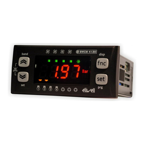
Push and release the “set” key to display
the normal set, the other unit of measure-
ment and the economy set can be dis-
played by pushing repeatedly the “set” key
whithin 5 seconds.
The corresponding led status lights on the
right side of the display shows the unit of
measurement selected, the active setpoint
displayed is identified by the “N” or “R”
green led, the other setpoint by the “N” or
“R” blinking light. By pushing “UP” or
“DOWN” arrow keys the selected setpoint
can be modified.
Compressors leds status
Before switching on an output the corre-
sponding green led blinks, this blinking pe-
riod depends on the delay parameters.
When the relay output has been swiched
on the corresponding red led will light.
Note: after turning on the power supply the
pressure may result out of range, therefore
to start up the system the EWCM controls
the compressors simply as the probe val-
ue were higher than the alarm limits.
After the time delay set to the parameter
“PAO”, if the probe value is still out of
range, the EWCM will start working follow-
ing the “CPP”, “SPPr” and “PoPr” parame-
ters setting.
How to display/reset the compressors
running hours
Push and release the “hrs” key to display
the first compressor running hours, the
“hrs” led will light; push the “UP” arrow
within 5 seconds to display the successive
compressors, the corresponding red led
will blink; the compressor running hours
can be reset by keeping pressed the
“mute” key for 5 five seconds; to exit this
procedure push and release the “hrs” key
once again.
How to display/modify the “MAINTE-
NANCE” and “IN SERVICE” status
Push and release the “maint” key to dis-
play the first compressor status, the corre-
sponding red led blinks and the “maint”
green led is on.
The “onLn” (on line) message means that
the output is “in service”.
To modify it keep the “mute” key pressed
for 5 seconds, the “oFLn” message means
that the output is in “maintenance” and the
corresponding red led will blink.
During the working cycle the “maintence”
status of a compressor is shown by the
blinking of the corresponding red and
green leds, in this case the output com-
pressor is always swiched off.
Digital alarm inputs
High and low pressurestat alarm
Terminal 5 and 6, “SEP” parameter.
Until the condition alarm on these termi-
nals is active, the EWCM keeps all the
compressor outputs switched off. This
kind of alarm does not need a manual re-
set.
If during the “PEI” interval time the number
of pressurestat errors reaches the “PEn”
value, the “Er0L” or the “Er0H” warning
message will be displayed. “Er0L” means
low pressurestat alarm and “Er0H” means
high pressurestat alarm. Press the “mute”
button for 5 seconds to reset this alarm.
This function can be excluded by setting
PEn = 0.
Alarm inputs linked to outputs
Terminals from 22 to 39, “ALIP” parameter.
Each compressor alarm protection must
be connected to the corresponding alarm
input (e.g. low compressor oil level, klixon
etc.). If one of these alarms is active, the
corresponding compressor output will be
switched off, the corresponding red led will
blink, the “alarm” red led will light and the
display will show the “Er02” warning mes-
sage.
This alarm does not need a manual reset.
Alarm silencing
When an alarm condition is active, the
alarm relay will be energized and the termi-
nal 1 and 2 are closed.
To silence an alarm push and release the
“mute” key, the alarm relay will be de-ener-
gized and the “alarm” led will blink if the
alarm condition is still active. The silencing
time depends on the “UAro” and “Aro” pa-
rameters setting.
If during the silencing time another alarm
becomes active, the silencing time will be
reset, and the new alarm condition will be
displayed.
Alarms that need a manual reset: keep
pressed the “mute” key, the display will
show the “CAnC” message and then the
“rES” message.
ALARM WARNING MESSAGES
Er0L…Er0H: Error Low…High.
Low and high pressurestat alarms. It
switches off all the compressor outputs.
Er01: Error 01.
Faulty probe alarm, see “CPP”, “SPr” and
“PoPr” parameters setting.
Er02: Error 02.
Inputs linked to outputs compressor
alarms. It switches off the corresponding
compressor output.
Er03: Error 03.
Low pressure alarm. It appears when the
probe value is lower than the Set – LAL.
Er04: Error 04.
High pressure alarm. It appears when the
probe value is higher than the Set + HAL.
Er11: Error 11.
Wrong clock programming. Check “Pri”,
“HoUr” and “dAY” parameters setting.
Er12: Error 12.
Wrong parameter programming. More
than the 9 available outputs have been
programmed. It needs a manual reset.
Er13: Error 13.
Wrong data memory. It needs a manual re-
set.
Er14: Error 14.
Maintenance alarm.
TECHNICAL DATA
Housing: black ABS plastic, 72x144 mm,
depth 120 mm.
Mounting: flush panel mount
(67x136 mm) with brackets.
Connections: quick-disconnect screw
terminal block.
Data storage: non-volatile EEPROM
memory.
Type of refrigerant: ammonia.
Suction sensor input: NTC or 4…20 mA
(scaleable).
Pressure switch input: one (1).
Global alarm output: relay 6(3)A 250V
AC.
Controller breakdown output: relay
6(3)A 250V AC.
Configurable outputs: 9 relays outputs
6(3)A 250V AC.
Alarm inputs: 9 inputs (250 Vac optoiso-
lated; other voltages on request).
Serial connection: RS-485 port for con-
nection to the TELEVIS system.
Consumption: 6 VA.
Power supply: 12, 24, 110, 220 Vac
±10%, 50/60 Hz.


