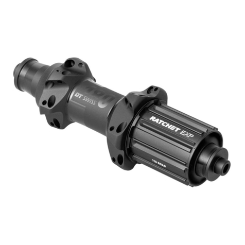
DT SWISS RATCHET EXP OS User manual

RATCHET EXP OS HUBS
TECHNICAL MANUAL
V2021.10

2
1. GENERAL .................................................................................................................3
1.1 Validity.......................................................................................................................... 3
1.2 Safety ........................................................................................................................... 3
1.3 Target group................................................................................................................. 3
1.4 Layout........................................................................................................................... 3
1.5 DT Swiss manual concept ........................................................................................... 3
1.6 How to use the manual ............................................................................................... 4
1.7 General Maintenance Information.............................................................................. 4
1.8 Environmental protection............................................................................................ 4
1.9 Exclusion of liability..................................................................................................... 4
1.10 Warranty....................................................................................................................... 4
2. MAINTENANCE OF THE REAR WHEEL HUB WITH RATCHET EXP®OS SYSTEM .5
2.1 Overview....................................................................................................................... 5
2.2 Required tools.............................................................................................................. 5
2.3 Required wearing parts and materials....................................................................... 6
2.4 Removing end caps, freewheel body and freewheel system ..................................... 7
2.5 Dismounting the bearing on the non drive side......................................................... 8
2.6 Dismounting the hub seal........................................................................................... 8
2.7 Dismounting the threaded ratchet ............................................................................. 9
2.8 Dismounting the bearing from the threaded ratchet................................................. 10
2.9 Cleaning and checking all parts ................................................................................. 11
2.10 Pressing the ball bearing into the threaded ratchet.................................................. 11
2.11 Screwing the threaded ratchet with the bearing into the hub shell.......................... 12
2.12 Mounting the bearing on the non drive side............................................................... 13
2.13 Mounting the hub seal................................................................................................. 15
2.14 Mounting the freewheel system.................................................................................. 16
2.15 Putting on the freewheel body and the end caps....................................................... 18
2.16 Check the functionality................................................................................................ 18
3. TROUBLE SHOOTING...............................................................................................19

Ratchet EXP OS - Technical Manual 3
1. GENERAL
1.1 VALIDITY
This manual describes the component specied on the front page and the footer. This manual is valid for the
design of the product as of 01.10.21. Deviations are possible and all items are subject to technical changes.
1.2 SAFETY
The safety instructions are classied as follows:
DANGER
...indicates a hazardous situation that, if not avoided, will result in death or serious injury.
CAUTION
… indicates a hazard with a medium level of risk which, if not avoided, may result in minor or moderate
injury.
NOTE
… indicates a potentially hazardous situation that may result in damage to property.
1.3 TARGET GROUP
This manual is intended for the user of the component and dealers. This manual offers the experienced user
the possibility to carry out minor service work himself. If you have any doubts about your own abilities, you
should denitely contact a specialist or a DT Swiss Service Center.
Any warranty claims will lapse if work is not carried out properly.
1.4 LAYOUT
The cover page and the footing provide information about the type of product and manual as well as the
version of the manual. The DT Swiss contact details can be found on the back. A list of all DT Swiss service
centers can be found at www.dtswiss.com.
This manual is intended for being printed as an A5 booklet. Only print this manual if electronic usage is not
possible.
1.5 DT SWISS MANUAL CONCEPT
The DT Swiss manuals are split into the following types of manuals:
• User Manual: Information for the end user on how to install and use the component.
• Technical Manual: Detailed information for the end user and the dealer on how to maintain the
component, spare parts and technical data.

4
1.6 HOW TO USE THE MANUAL
The steps described in this manual must be carried out in the order they are shown. If steps are ignored or
executed in a wrong order, the function of the component cannot be guaranteed.
1.7 GENERAL MAINTENANCE INFORMATION
Unless otherwise specied, moving parts, threads, O-rings and seals must be greased before assembly.
CLEANING
For an optimal result of the maintenance work, every component that will be disassembled must be cleaned.
Only use cleaners which do not damage the components. Especially the cleaning of O-rings and seals
requires mild cleaners. Observe the instructions for use of the respective cleaner.
DT Swiss recommends the following cleaners:
• Motorex Rex
• Motorex Swissclean
• Motorex OPAL 2400, 3000 OPAL, OPAL 5000
Use soap water or similar mild cleaners for external cleaning.
TOOLS
To ensure a damage-free mounting and dismounting of the components, only use the tools which are
mentioned in this manual. Special tools are indicated at the beginning of a chapter in the table "Required
Tools".
The use of different tools is at the discretion of the user. If components are damaged by the usage of differing
tools, the user is liable.
DT Swiss special tools are precision tools. Damage-free mounting and dismounting of the components can
only be ensured if the tools are working properly and if the condition of the tools are perfect. Always keep the
tools in their original packaging or adequate devices to prevent damage.
1.8 ENVIRONMENTAL PROTECTION
The statutory regulations shall apply. Whenever possible, avoid creating waste. Waste, especially carbon,
lubricants, cleaners and any other uids must be disposed in an environmentally compatible manner.
Only print this manual if electronic usage is not possible.
1.9 EXCLUSION OF LIABILITY
The activities listed in this manual may only be carried out by persons with sufcient specialist knowledge.
The user is liable for any damage or consequential damage caused by wrongly maintained or installed
components. If you have doubts, please contact your region's DT Swiss pro level service center.
1.10 WARRANTY
Warranty conditions, see www.dtswiss.com

Ratchet EXP OS - Technical Manual 5
2. MAINTENANCE OF THE REAR WHEEL HUB WITH RATCHET EXP®OS SYSTEM
2.1 OVERVIEW
12
3
4
5678910 11
12 13
1 end cap non drive side 8 spacer
2 ball bearing non drive side 9 loose ratchet
3axle 10 spring
4 hub shell 11 washer
5 ball bearing drive side 12 freewheel body
6 threaded ratchet 13 end cap drive side
7 hub seal
2.2 REQUIRED TOOLS
Tools Specication Quantity Article number
installation cylinder Ø15 x 26 x 40 mm 1 HXTXXX00N5314S
mounting / dismounting tool for the threaded
ratchet 1 HXTXXX00N3157S
mounting / dismounting tool ball bearing
drive side 1 HXTXXX00N6106S
installation tool for hub seal 1 HXTXXX00N1000S

6
2.3 REQUIRED WEARING PARTS AND MATERIALS
Wearing parts / Materials Specication Quantity Article number
DT Swiss universal grease 20 g HXTXXX00NMG20S
DT Swiss special grease
• 20 g tube 20 g HXT10032508S
ball bearing drive side
1728 Ø17 / 28 x 7 mm 1 HSBXXX00N9115S
ball bearing non drive side
1526 Ø15 / 26 x 7 mm 1 HSBXXX00N3741S
hub seal 1 HSOXXX00N1031S
spacer Ø25.9 / 19.9 x 2.3 mm 1 HCD13300X9643S
Service Kit
Content
• 1x spring
• 1x DT Swiss special grease 20 g tube
• 1x EXP OS 30T ratchet
• 1x ratchet EXP OS 30 T M32
• 1x spacer Ø25.9 / 19.9 x 2.3 mm
1 HWYXXX00N9952S

Ratchet EXP OS - Technical Manual 7
2.4 REMOVING END CAPS, FREEWHEEL BODY AND FREEWHEEL SYSTEM
1. Pull off both end caps by hand.
If the end caps cannot be pulled off by hand,
clamp the end caps carefully into a vise with
ground clamping jaws and pull the hub / wheel
upwards.
2. Pull the freewheel body off the hub.
3. Pull the spacer off the axle.
4. Remove the ratchet and the washer from
the freewheel body.

8
2.5 DISMOUNTING THE BEARING ON THE NON DRIVE SIDE
1. Tap out the ball bearing on the non drive
side with a plastic hammer with slight
hammer strokes onto the axle.
2. Remove the ball bearing from the axle.
2.6 DISMOUNTING THE HUB SEAL
1. Using a slotted screwdriver with a blade
width of about 2.5 mm, slide under the hub
seal into one of the notches of the ratchet.
2. Turn the screwdriver 90° around its
longitudinal axis and push the hub seal out
of its seat.

Ratchet EXP OS - Technical Manual 9
2.7 DISMOUNTING THE THREADED RATCHET
Due to the torque which acts on the threaded ratchet during pedaling, the threaded ratchet
tightens during riding. We recommend loosening the ratchet only when the wheel is complete as
the lever is much larger.
1. Clamp the mounting / dismounting tool for
the threaded ratchet into the vice.
2. Fit the hub or wheel onto the tool in such a
way that the teeth of the tool engage in the
teeth of the threaded ratchet.
3. Insert the axle into the hub and through the
threaded ratchet.
HXTXXX00N3157S
4. Put the installation cylinder onto the non
drive side of the hub.
5. Loosen and screw off the ratchet by turning
the hub counterclockwise.
6. Remove the hub from the tool. HXTXXX00N5314S
7. Remove the ratchet with the bearing.

10
2.8 DISMOUNTING THE BEARING FROM THE THREADED RATCHET
1. Put the threaded ratchet with the bearing
into the mounting / dismounting tool.
→The toothing of the threaded ratchet
must face upwards.
→Put the ratchet on the side of the tool
with the tting diameter. The ratchet
may only move minimally in the tool.
HXTXXX00N6106S
2. Slide the axle with its long end through the
ball bearing.
3. Use a plastic hammer to knock the ball
bearing out of the ratchet with light hammer
strokes.
4. Remove the ratchet and the bearing from
the tool.

Ratchet EXP OS - Technical Manual 11
2.9 CLEANING AND CHECKING ALL PARTS
1. Clean all parts of the hub, threaded ratchet, sleeve, spring and end caps. The existing grease
must be completely removed from the hub body and from the threaded ratchet.
2. Check the ratchets for wear.
The wear of the ratchets usually starts at
the outer circumference and shows itself by
strongly attened edges with uneven wear.
In case of heavy wear, the ratchets must be
changed immediately.
3. Check the freewheel body for damages.
→Grooves from the cassette are no damages. These are normal signs of usage.
2.10 PRESSING THE BALL BEARING INTO THE THREADED RATCHET
1. Slightly grease the contact surface of the
bearing and the threaded ratchet.
2. Put the threaded ratchet with the toothing
facing downwards onto the mounting /
dismounting tool.
→Put the ratchet on the side of the tool
with the tting diameter. The ratchet
may only move minimally in the tool.
3. Put a new ball bearing with the colored side
facing downwards onto the ratchet.
1-2 mm
HXTXXX00N6106S
4. Carefully press the bearing into the ratchet with light hammer strokes on the outer ring of the
ball bearing until the bearing protrudes 1 to 2 mm beyond the ratchet.
→The ball bearing must not be pressed further into the ratchet.

12
2.11 SCREWING THE THREADED RATCHET WITH THE BEARING INTO THE HUB SHELL
1. Slightly grease the threaded ratchet and the thread of the hub shell with universal grease.
2. Clamp the mounting / dismounting tool for
the threaded ratchet into the vice.
3. Place the threaded ratchet with pressed-in
ball bearing on the tool.
4. Slide the axle with its long end through the
ball bearing.
5. Put the hub or the wheel onto the mounting
/ dismounting tool.

Ratchet EXP OS - Technical Manual 13
6. Push the installation cylinder onto the non
drive side of the hub.
→By using the axle and the installation
cylinder, the hub shell is guided when
the ratchet is screwed on. The ratchet
cannot cant.
7. Tighten the threaded ratchet as tight as
possible by turning the hub clockwise by
hand.
HXTXXX00N5314S
8. Remove the hub from the mounting / dismounting tool and put the tool out of the vice.
2.12 MOUNTING THE BEARING ON THE NON DRIVE SIDE
1. Make sure that the axle is in the hub with
the long side rst.
2. Grease the bearing seat and the axle with
universal grease.
3. Push a new bearing on the axle with the
colored side facing outwards.

14
4. Clamp the mounting / dismounting tool for
the threaded ratchet into the vice.
5. Put the hub on the tool in the vice.
6. Put the installation cylinder onto the
bearing.
7. Tap in the ball bearing carefully with slight
hammer strokes. HXTXXX00N5314S
HXTXXX00N3157S
8. Check the ball bearings.
→It must be possible to turn the hub with
slight resistance.
→The hub must not have axial play.
9. Tap the bearing on the non drive side in or
out and repeat previous steps until the hub
is turning smoothly.

Ratchet EXP OS - Technical Manual 15
2.13 MOUNTING THE HUB SEAL
NOTE
RISK OF DAMAGE TO THE HUB BY USING THE WRONG TOOL!
If the mounting tool HXTXXX00N5026S is used to mount the hub seal, the axle may be damaged
or the ball bearing on the non-drive side may be loosened from its bearing seat.
• Only use the mounting tool HXTXXX00N1000S with the tapered bore.
1. Put the hub seal onto the mounting tool.
HXTXXX00N1000S
2. Put the installation tool with the hub seal
onto the axle.

16
NOTE: The hub must not be supported by
the ball bearing on the non-drive side when
pressing in the hub seal.
3. Put the mounting tool with the hub seal
onto the axle.
4. Push on the installation cylinder and drive
in the hub seal with slight hammer strokes.
2.14 MOUNTING THE FREEWHEEL SYSTEM
DANGER
RISK OF INJURY DUE TO LIMITED FREEWHEEL FUNCTION DUE TO INCORRECT
LUBRICATION!
If too much grease is applied on the ratchets, the actuation of the ratchets may not work.
The
ratchets may slip during pedaling.
• Only apply a thin, even layer of grease.
• Only use the red DT Swiss special grease.
1. Apply DT Swiss special grease evenly to the
outer and the inner toothing of the ratchets
using a ne brush.
→For an optimal functionality of the
freewheel system, a thin layer of grease
is sufcient.

Ratchet EXP OS - Technical Manual 17
2. Put the spacer onto the axle.
3. Put the spring onto the washer and put the
ratchet o to the spring.
4. Put the washer, spring, and ratchet into the
freewheel body.

18
2.15 PUTTING ON THE FREEWHEEL BODY AND THE END CAPS
1. Put the freewheel body onto the hub.
2. Check if the freewheel body can be turned
and if the ratchets are engaging.
3. Grease both bearings and the inner side of
both end caps.
4. Put on the left and the right end cap.
→The shorter end cap must be placed on
the drive side.
2.16 CHECK THE FUNCTIONALITY
1. Turn the freewheel body in both directions.
→The freewheel body can be turned
counterclockwise easily.
The ratchets engage audibly and
perceptibly.
→The freewheel body cannot be turned
clockwise.
2. Check the tightness of the end caps.
→ The end caps are rmly seated on the
axle and are fully pushed on.

19Ratchet EXP - Technical Manual
3. TROUBLE SHOOTING
Issue Reason Solution
Freewheel is blocked Spacer was forgotten during
assembly.
Check correct assembly, see “2.1
Overview”, page 5.
Spacer was compressed by
overtightening the thru axle.
Measure the length of the spacer.
If the spacer is shorter than 10.7
mm, it must be replaced.
Freewheel does not engage
/ slips
Loose ratchet is mounted
upside down.
Check correct assembly, see “2.1
Overview”, page 5.
Too much or wrong grease on
the ratchets.
Clean and grease ratchets, see
“2.14 Mounting the freewheel
system”, page 16.
Ratchets are worn. Replace ratchets.
Spring was forgotten during
assembly.
Check correct assembly, see “2.1
Overview”, page 5.
Hub has axial play Ball bearings were not
mounted correctly.
Check correct assembly, see “2.1
Overview”, page 5.
Ball bearings are worn out. Replace ball bearings.
Hub rotates stify Ball bearings are worn out. Replace ball bearings.
Ball bearing non drive side
too tight.
Check correct assembly, see “2.1
Overview”, page 5.
Mounting sequence of the ball
bearings not observed.
Ball bearing pressed too far
into the threaded ratchet
before assembly.
Hub makes noise Ball bearings are worn out. Replace ball bearings.
Notches from the cassette
on the freewheel body.
The steel cassette works itself
into the web of the freewheel
body.
Remove bad notches from the
rotor using a le.
Freewheel body rotates with
difculty.
Ball bearings in the freewheel
body are worn out.
Replace freewheel body.
Freewheel is too noisy / too
quiet.
The perception of the freewheel sound is very subjective. While
some riders prefer a loud freewheel sound, other riders want
a quiet freewheel. In principle, the freewheeling sound can be
inuenced by the amount of grease between the ratchets. Less
grease increases the freewheeling sound, but at the same time
leads to higher wear.

DT SWISS ASIA LTD.
No.5, Jingke 5th Rd., Nantun District
Taichung City 408
Taiwan (R.O.C.)
DT SWISS DEUTSCHLAND GmbH
Albert-Einstein-Strasse 3
59302 Oelde
Germany
DT SWISS POLSKA Sp. z o.o.
ul. Towarowa 36
PL-64-600 Oborniki
Poland
DT SWISS AG
Längfeldweg 101
CH - 2504 Biel/Bienne
DT SWISS, INC.
2493 Industrial Blvd.
USA - Grand Junction, CO 81505
DT SWISS (FRANCE) S.A.S.
Parc d‘Activites de la Sarrée
Route de Gourdon
F - 06620 Le Bar sur Loup
Subject to technical alterations, errors and misprints excepted.
All rights reserved.
© by DT SWISS AG
www.dtswiss.com
HXD10000004420S
Table of contents
Other DT SWISS Switch manuals
Popular Switch manuals by other brands

Clarion
Clarion MSS7100 owner's manual

D-Box
D-Box HaptiSync Hub user manual

IBM
IBM RackSwitch G8264T Product guide

Brocade Communications Systems
Brocade Communications Systems A7533A - Brocade 4Gb SAN Switch Base reference guide

Gefen
Gefen HDMI-242 user manual

Silvercrest
Silvercrest 285220 Operation and safety notes