DTC SOLO7 Series User manual

Resource Identifier 100145
Revision: 19.1
SOLO7 Transmitter User Guide
Commercial in Confidence

Revision 19.1
SOLO7 Transmitter User Guide
Copyright © 2013 Domo Tactical Communications (DTC) Limited. All rights reserved.
Commercial in Confidence
Page 0-1
0. Preface
0.1 About this Document
This document contains relevant information required to identify, install and control the equipment or
system.
Since the available functions can be licensed and depend on the specific implementation, not all the
functions and or applications contained in this document may be relevant or applicable to the system you
will be working with.
The actual presentation may differ from those in this document due to hardware or software changes.
0.2 Intended Audience
This document is meant for anyone interested in how the system can be used, but it is of most benefit to:
Operators who oversee the daily operation of the equipment
Installers who are responsible for the pre-installation, on-site installation and configuration of the
system in the end-user environment
Maintainers who are responsible for maintaining the equipment or system
0.3 Notice about this Publication
While DTC makes every attempt to maintain the accuracy of the information contained in its product
manuals, the information is subject to change without notice.
Performance specifications included in this manual are for guidance. All particulars are given by DTC in
good faith, actual performance may vary.

Revision 19.1
SOLO7 Transmitter User Guide
Copyright © 2013 Domo Tactical Communications (DTC) Limited. All rights reserved.
Commercial in Confidence
Page 0-2
0.4 Text Conventions
This document uses these conventions to identify text that has a special meaning:
Description Example
TEXT in capitals represents a key press on the keyboard.
The + sign means hold down the first key and press the second key.
ESC, F1, SHIFT
CTRL+C
<
Text
> Serves as a placeholder for variable text that is replaced as
appropriate, the text may be written in italics.
Use the filename
<
system_name
>.sys for…
Text in italics can represent a link to place in the existing document
(often these are hyperlinks) or a reference to another document.
Refer to
Section 0.4
,
Text
Conventions
.
Text in bold emphasises a new word or term of significance. We call this a protocol and its
function is…
Successive software menu selections are shown using arrows to
indicate sub-menus. This is often shown in bold.
Select Configuration>Global
then edit…
0.5 Symbols
This document uses these symbols to highlight important information:
WARNING: A notice of when a situation may result in personal injury or loss of life, or destruction of
equipment.
CAUTION: A notice of when a situation may result in loss of data or damage to equipment or systems.
Note:A notice to draw attention to something or to supply additional information.
0.6 Copyright
This document contains information that is proprietary to Domo Tactical Communications (DTC) Ltd. Any
copying or reproduction in any form whatsoever is prohibited without the written permission of DTC.
© 2013 Copyright Domo Tactical Communications (DTC) Limited. All rights reserved.

Revision 19.1
SOLO7 Transmitter User Guide
Copyright © 2013 Domo Tactical Communications (DTC) Limited. All rights reserved.
Commercial in Confidence
Page 0-3
0.7 Related Documents
All DTC documents can be downloaded from WatchDox. See
Section 8.1
.
Document Source
PRORXD Broadcast Receiver User Guide DTC
0.8 Document History
This is a controlled document, written and produced by the DTC Technical Publications team. Changes are
recorded in the table below.
Revision Date Author Summary of Changes
1.0 11/11/2013 RC First release
8.0 31/10/2014 RC FCC statement
9.0 14/12/2015 IR Recommended video settings
11.0 22/06/2016 IR DTC rebrand
13.0 06/01/2017 IR Upgrade procedures
17.0 26/10/2017 IR Customer logo on test pattern.
18.0 04/12/2017 IR SOL7TX SDI/ASI In and LED metalwork change.
18.1 11/06/2018 IR Added caution to command oprm and v1qm.
18.2 18/01/2019 IR Clarified aircraft safety statement.
18.3 01/03/2019 IR Dual pedestal, PES per frame.
18.4 16/03/2020 IR New document layout.
19.0 02/04/2020 IR Updates for sw 3.4.0.
19.1 07/09/2021 IR Minor text update.

Revision 19.1
SOLO7 Transmitter User Guide
Copyright © 2013 Domo Tactical Communications (DTC) Limited. All rights reserved.
Commercial in Confidence
Page 0-4
Contents
0. Preface......................................................................................................0-1
0.1 About this Document .................................................................................................................... 0-1
0.2 Intended Audience ........................................................................................................................ 0-1
0.3 Notice about this Publication........................................................................................................ 0-1
0.4 Text Conventions........................................................................................................................... 0-2
0.5 Symbols ........................................................................................................................................ 0-2
0.6 Copyright ...................................................................................................................................... 0-2
0.7 Related Documents....................................................................................................................... 0-3
0.8 Document History.......................................................................................................................... 0-3
1. Product Overview ......................................................................................1-1
1.1 Description.................................................................................................................................... 1-1
1.2 Basic Specifications ..................................................................................................................... 1-1
1.3 Approval Notices........................................................................................................................... 1-1
1.4 FCC Certification........................................................................................................................... 1-2
2. Product Package .......................................................................................2-3
2.1 Packaging Overview...................................................................................................................... 2-3
2.2 Parts List ...................................................................................................................................... 2-3
2.3 Accessory Options......................................................................................................................... 2-3
2.4 Licensing Options ......................................................................................................................... 2-4
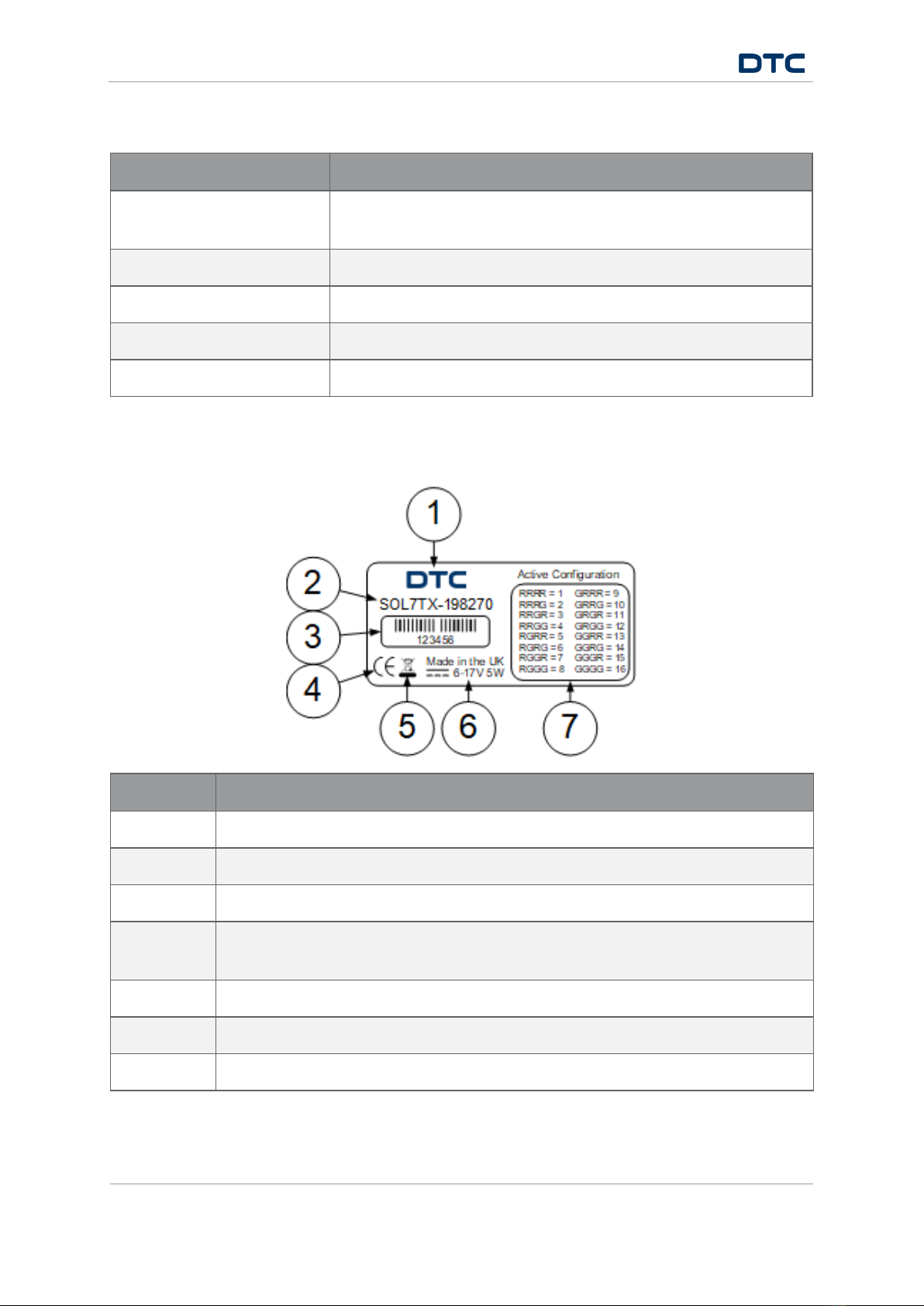
2.5 Label ............................................................................................................................................. 2-4
3. Controls, Connections and Indicators........................................................3-5
3.1 Front Panel.................................................................................................................................... 3-5
3.2 Rear Panel .................................................................................................................................... 3-6
3.3 Right Side Panel ........................................................................................................................... 3-6
4. Getting Started .........................................................................................4-7
4.1 Starting and Stopping the Transmitter......................................................................................... 4-7
4.1 Domo Device Controller................................................................................................................. 4-7
4.2 Connecting your PC to the SOLO7 Transmitter.............................................................................. 4-8
4.3 Domo Device Controller Primary Window..................................................................................... 4-10
4.4 Performing a Quick Setup ........................................................................................................... 4-11
5. Domo Device Controller Operation ...........................................................5-13
5.1 Introduction ................................................................................................................................ 5-13
5.2 Unit Status Panel........................................................................................................................ 5-13
5.3 Switch Panel ............................................................................................................................... 5-15
5.4 Advanced>Unit Window.............................................................................................................. 5-16
5.5 Advanced>Modulation Window................................................................................................... 5-20
5.6 Advanced>Audio Window ........................................................................................................... 5-25
5.7 Advanced>Video Window............................................................................................................ 5-28

Revision 19.1
SOLO7 Transmitter User Guide
Copyright © 2013 Domo Tactical Communications (DTC) Limited. All rights reserved.
Commercial in Confidence
Page 0-5
5.8 Advanced>Misc Window ............................................................................................................. 5-31
5.9 Licensing Upgrade ...................................................................................................................... 5-34
5.10 Firmware Upgrade................................................................................................................... 5-35
6. Advanced Operation ................................................................................6-36
6.1 High Linearity and Low Power Modes .......................................................................................... 6-36
6.2 Domo Device Controller Logging Mode........................................................................................ 6-38
7. Appendix A – Reference Material.............................................................7-40
7.1 Temperature Control Tips............................................................................................................ 7-40
7.2 Pinout – SOL7TX ......................................................................................................................... 7-41
7.3 Recommended Manual Video Encoder Settings .......................................................................... 7-42
7.4 Remote Commands..................................................................................................................... 7-43
8. Appendix B – After-Sales Support ...........................................................8-58
8.1 Documentation and Software...................................................................................................... 8-58
8.2 Contact Technical Support.......................................................................................................... 8-58
8.3 Using the DTC RMA Service......................................................................................................... 8-58
9. Appendix C – Safety and Maintenance ....................................................9-60
9.1 Cautions and Warnings .............................................................................................................. 9-60
9.2 Repairs and Alterations .............................................................................................................. 9-61
9.3 Caring for your Equipment.......................................................................................................... 9-61
9.4 Charging..................................................................................................................................... 9-61
9.5 Working with Lithium Batteries................................................................................................... 9-61
9.6 Cleaning ..................................................................................................................................... 9-62
9.7 Storage ....................................................................................................................................... 9-62
10. Appendix D – Glossary .......................................................................10-63

Revision 19.1
SOLO7 Transmitter User Guide
Copyright © 2013 Domo Tactical Communications (DTC) Limited. All rights reserved.
Commercial in Confidence
Page 1-1
1. Product Overview
1.1 Description
A miniature feature rich COFDM digital video transmitter designed specifically for situations when reliable
operation and power consumption are critical. Offering several user-selectable modes allowing optimum
selection of range and performance for flexibility in any environment. The SOLO7 Transmitter is ideal for
battery powered applications requiring long term deployment, such as unmanned aerial vehicles or
concealments.
The SOLO7 Transmitter is highly power efficient drawing typically 3.7W and weighing only 116g and is
designed to support mounting on any kind of vehicle, manned or unmanned. Now even more capable with
additional digital input for either SD-SDI cameras, or ASI for remux/relay applications.
1.2 Basic Specifications
Size L 64mm, W 65mm, H 18mm
Weight 116g
Operating Temperature -10°C to +50°C
Power Consumption Typically, 3.7W @ 100mW RF power with
additional 2.0W for >6.0GHz down to 3.0W @
10mW RF power
DC Input 5.9V to 17.8V reverse polarity protected
1.3 Approval Notices
1.3.1 EMC/Safety and CE Marking
The equipment has been designed to meet and has been tested against harmonized EMC and safety
standards. The CE mark is indicated on all SOLO7 Transmitter product labels.
The CE Declaration of Conformity as well as the technical file are available on request.

Revision 19.1
SOLO7 Transmitter User Guide
Copyright © 2013 Domo Tactical Communications (DTC) Limited. All rights reserved.
Commercial in Confidence
Page 1-2
1.4 FCC Certification
Note: Not currently applicable for OBTX.
1.4.1 FCC Subpart 15A Rule Section 15.21
CAUTION: The user of an intentional or unintentional radiator shall be aware that changes or modifications
not expressly approved by DTC could void the user’s authority to operate the equipment.
1.4.2 FCC Subpart 15B Rule Section 15.105
Note: This equipment has been tested and found to comply with the limits for a Class B digital device,
pursuant to part 15 of the FCC Rules. These limits are designed to provide reasonable protection against
harmful interference in a residential installation. This equipment generates, uses and can radiate radio
frequency energy and, if not installed and used in accordance with the instructions, may cause harmful
interference to radio communications. However, there is no guarantee that interference will not occur in a
particular installation. If this equipment does cause harmful interference to radio or television reception,
which can be determined by turning the equipment off and on, the user is encouraged to try to correct the
interference by one or more of the following measures:
Reorient or relocate the receiving antenna
Increase the separation between the equipment and receiver
Connect the equipment into an outlet on a circuit different from that to which the receiver is connected
Consult the dealer or an experienced radio/TV technician for help
1.4.3 FCC Subpart 15A Rule Section 15.19(a) (3)
Note: This equipment has been tested and found to comply with the limits for a Class B digital device,
pursuant to part 15 of the FCC Rules.
This device complies with part 15 of the FCC Rules. Operation is subject to the following two conditions: (1)
This device may not cause harmful interference, and (2) this device must accept any interference received,
including interference that may cause undesired operation.
1.4.4 RF Exposure Guidance
The unit must be operated at least 20cm away from the body for RF exposure compliance purposes.

Revision 19.1
SOLO7 Transmitter User Guide
Copyright © 2013 Domo Tactical Communications (DTC) Limited. All rights reserved.
Commercial in Confidence
Page 2-3
2. Product Package
2.1 Packaging Overview
Verify that all the components have been included in the package as shown in the packing list. Retain the
packing list and all the packing materials for storage.
The part numbers are useful for identification and if you need to order a new part. The codes in the packing
list mean:
CA – cable assembly
SA – sub assembly
AP – assembly part
Note: If you don’t have all the parts or you are not happy with the condition of your delivered product, please
call DTC and we’ll get this solved for you. See
Section 8.2
.
2.2 Parts List
Part Number Description
SOL7TX SOLO7 Transmitter, 2452.5-2481.0MHz
AP007377 USB A to Micro USB B 1m cable
CA0002 12VDC power cable Lemo to banana plugs
CA3186 Hirose to power Lemo, video BNC(f) and audio 3.5mm jack cable
2.3 Accessory Options
If you have purchased these options, they will also be in the package.
Part Number Description
ANT2SMA-210250 2dBi omni antenna, 2.10-2.50GHz SMA (m)
CA0610 Hirose power and control cable
CA0611 Hirose power and video cable
CA0612 Hirose power, video and audio cable
CA3148 MCX 75Ω to BNC female cable
NTXBAT Li-ion battery pack 7.4V, 2250mAh 4-pin Lemo
NTXBATCH Battery charger for NTXBAT (multi-region).

Revision 19.1
SOLO7 Transmitter User Guide
Copyright © 2013 Domo Tactical Communications (DTC) Limited. All rights reserved.
Commercial in Confidence
Page 2-4
2.4 Licensing Options
Part Number Description
Silver (included) DVB-T, Ultra Mobile Video Link (UMVL), MPEG-4 SD H.264, Dual
Pedestal
Gold Silver plus MPEG-4 ASP, 2.5MHz and 1.25MHz Modulation
Platinum Gold plus 625kHz Modulation
AES128TX AES 128-Bit Encryption
AES256TX AES 256-Bit Encryption
2.5 Label
No Description
1 Manufacturer
2 SOL7TX product code.
3 Barcoded, six-digit serial number. This may be needed during a support call.
4 The CE mark certifies that a product has met EU consumer safety, health or
environmental requirements.
5 Disposal marking
6 Power requirement
7 LED sequence which indicates the active configuration. See
Section 3.1
.

Revision 19.1
SOLO7 Transmitter User Guide
Copyright © 2013 Domo Tactical Communications (DTC) Limited. All rights reserved.
Commercial in Confidence
Page 3-5
3. Controls, Connections and Indicators
3.1 Front Panel
No Item Used for...
1 SMA receptacle
(socket).
Connect an antenna to the SMA receptacle on the top panel of the
transmitter unit.
Peak antenna gain must be no greater than 14.5dBi. DTC recommends
the use of 2dBi antenna accessory, see
Section 2.3
.
CAUTION: Do not over tighten the antenna – hand tight only!
2 Config button The config button can be operated with a blunt but pointed tool. A
ballpoint pen is ideal for this purpose.
When you want to confirm the config that the SOL7TX is set to, press
the config button once. The LEDs will flash accordingly.
When you want to change the config, press and hold the config button
until the red LED lights. The config will change incrementally, and the
LEDs will flash accordingly.
Note: See the label on the top panel for the LED config sequence, refer
to
Section 2.5
.
3 Red/green dual
colour LED
The red LED is used to indicate the video input status:
No light = video locked or off.
Flash = video error.
The green LED is used to indicate the RF input status:
No light = RF off
Solid ON = RF on
Note: The red/green LED is also used to indicate the config number that
the SOL7TX is set to. See Config button above.

Revision 19.1
SOLO7 Transmitter User Guide
Copyright © 2013 Domo Tactical Communications (DTC) Limited. All rights reserved.
Commercial in Confidence
Page 3-6
3.2 Rear Panel
The rear panel will accommodate the supplied CA3186 to provide DC power (in conjunction with CA0002),
video and audio inputs.
No Item Used for...
1 16-way Hirose 3500
series socket
Connect CA3186 here to provide DC power (in conjunction with
CA0002), composite video and audio inputs.
Data signals also provided are RS232 control and chained data.
Optional cables can be supplied.
2 MCX 75Ω socket SD-SDI or ASI video input. The optional cable CA3148 will adapt the
MCX connection to BNC.
3.3 Right Side Panel
On the right side panel there is a USB control port socket for configuring the unit using the Device Controller
application. Connect the supplied AP007377 cable from the SOL7TX to a PC or laptop.

Revision 19.1
SOLO7 Transmitter User Guide
Copyright © 2013 Domo Tactical Communications (DTC) Limited. All rights reserved.
Commercial in Confidence
Page 4-7
4. Getting Started
4.1 Starting and Stopping the Transmitter
SOLO7 Transmitters don’t have power switches, they are powered up and down directly from the power
source. Before shutting down, ensure the unit is not in sleep mode.
4.1 Domo Device Controller
4.1.1 Introduction
Domo Device Controller provides users with convenient access to the most usual features and functions of
the device. Domo Device Controller allows you to set up to sixteen presets and have control of all parameters
of the unit.
4.1.2 Install the Controller on your PC
Domo Device Controller comes as an executable installer package.
Note: You can download the latest version from the DTC’s Watchdox facility, see
Section 8.1
.
Double-click the executable to install this software on your PC.
A desktop icon will appear on your desktop.

Revision 19.1
SOLO7 Transmitter User Guide
Copyright © 2013 Domo Tactical Communications (DTC) Limited. All rights reserved.
Commercial in Confidence
Page 4-8
4.2 Connecting your PC to the SOLO7 Transmitter
Ensure your transmitter is connected by either USB or serial control and is powered up.
Double-click Domo Device Controller icon on the computer desktop to open the Domo Device Controller.
Click the connection button.
Select USB or Serial Port in the device connection window (dependent on your device connection). You’ll see
the USB identification number or serial port Com Port of the Transmitter.

Revision 19.1
SOLO7 Transmitter User Guide
Copyright © 2013 Domo Tactical Communications (DTC) Limited. All rights reserved.
Commercial in Confidence
Page 4-9
Click the Connect button. Device Controller reads the SOLO7 Transmitter configurations and the primary
window opens.

Revision 19.1
SOLO7 Transmitter User Guide
Copyright © 2013 Domo Tactical Communications (DTC) Limited. All rights reserved.
Commercial in Confidence
Page 4-10
4.3 Domo Device Controller Primary Window
No Name Description
1 Configuration
presets
Sixteen (or eight) preset configurations can be stored. The blue button
is the currently active preset.
2 Basic settings When you have selected a preset, the basic settings for that
configuration can be edited from the primary window. These can also
be configured in the Advanced window.
3 Range mode and
video quality
The modulation and video settings will be automatically selected for
optimum performance by using these sliders.
4 Unit status Indicators to report things like RF Status, Video Lock, Audio Lock,
Temperature and Connection Status.
5 Switch panel Buttons to take you to: The Advanced window, the Engineer window, the
Upload window and to quit the Domo Device Controller.

Revision 19.1
SOLO7 Transmitter User Guide
Copyright © 2013 Domo Tactical Communications (DTC) Limited. All rights reserved.
Commercial in Confidence
Page 4-11
4.4 Performing a Quick Setup
The SOLO7 Transmitter can be quickly setup from the primary window.
Basic Setting Options Description
Output frequency A frequency in the range of
the unit.
Type in the frequency that you want this device
to use in megahertz (MHz).
Click the green tick to save the setting.
Video source Off
Composite 1
Composite 2
S-Video
Select the video source.
Audio source Off
Balanced
Unbalanced
OBTX and BNTX have balanced analogue audio
inputs.
Modulation scheme NB/UMVL
DVB-T
Select the modulation scheme for the system.

Revision 19.1
SOLO7 Transmitter User Guide
Copyright © 2013 Domo Tactical Communications (DTC) Limited. All rights reserved.
Commercial in Confidence
Page 4-12
Basic Setting Options Description
Video source format Automatic
PAL
NTSC
NTSC NP
Select the video format that matches the camera
you are using.
Alternatively, the Automatic setting determines
the video source.
Power up standard in Automatic mode defaults to
PAL. This can be changed by setting the input to
NTSC NP for example and then back to Automatic.
Encryption mode Off
ABS
AES128
AES256
All Transmitters have ABS, but the AES modes are
all license dependent.
Encryption key
Dialog entry Enter the encryption key.
ABS=8 characters
AES128=32 characters
AES256=64 characters
Range Mode Slider adjustment Move the slider towards the left to get shorter
ranges but higher picture and audio quality.
Video Quality Slider adjustment The options will differ dependent on video and
range settings.
Move the slider to the left to get lower resolution
at a higher frame rate.
Note: Some modulation and encryption modes are licensed features. Unlicensed features may be marked
with a padlock icon.

Revision 19.1
SOLO7 Transmitter User Guide
Copyright © 2013 Domo Tactical Communications (DTC) Limited. All rights reserved.
Commercial in Confidence
Page 5-13
5. Domo Device Controller Operation
5.1 Introduction
To get the most from your radio system you must customise the programming for your operations and area.
The SOLO7 Transmitter uses the Domo Device Controller software running on your PC which enables you to
perform many configuration tasks quickly and easily. These next topics tell you how to connect your PC to
the Nano Transmitter and then use your Domo Device Controller to configure the unit.
If the Device Controller menu shows a ‘lock’ symbol next to a feature, this means that it is not
available for your device variant or that it is missing a license.
5.2 Unit Status Panel
No Name Options Description
1 RF Button Red=RF off
Green=RF on
Click to toggle RF on or off.
2 Video Lock Red=unlocked
Green=locked
Tells you if the unit has successfully locked to the
video source.
Unlocked will also be shown if video is disabled.
3 Audio Lock Red=unlocked
Green=locked
Tells you if the unit has successfully locked to the
audio source.
Unlocked will also be shown if audio is disabled.

Revision 19.1
SOLO7 Transmitter User Guide
Copyright © 2013 Domo Tactical Communications (DTC) Limited. All rights reserved.
Commercial in Confidence
Page 5-14
No Name Options Description
4 Temperature Green
Yellow
Red
An indication of the temperature of the FPGA. Try to
keep it green.
0°C to 59°C shown in green.
60°C to 84°C shown in yellow.
85°C or above shown in red.
CAUTION: If it changes to red, switch the unit off
and allow it to cool.
>95°C some video encoder functionality is
disabled to try and reduce temperature; video
quality will be affected.
>99°C the unit will shut down and restart to avoid
permanent FPGA damage.
5 Logging Greyed – unavailable
White – logging
Logging is normally off by default.
Logging is enabled by using a command line
switch which is fully described in
Section 6.2
.
6 Connect Button Red=disconnected
Green=connected
Click to connect or disconnect the Domo Device
Controller serial connection.
The application will remain open when
disconnected.
Other manuals for SOLO7 Series
1
Table of contents
Other DTC Transmitter manuals
Popular Transmitter manuals by other brands

Enersound
Enersound T588-15 user manual

Westlock Controls Corporation
Westlock Controls Corporation D510 Installation and operation manual

Greystone Energy Systems
Greystone Energy Systems CDD4B1 Series installation instructions

AMG
AMG AMG2683 instruction manual

Sartorius
Sartorius PR5230 Instrument manual

Audiovox
Audiovox Prestige APS-92BT-CL Program guide