The Armstrong Monitoring Corporation AMC-400 Series User manual

AMC-400
Series
Digital Transmitter
with Smart Sensor
2
USER MANUAL
IMPORTANT:
Please read the installation and operating instructions completely and
carefully before starting.
Filename: 3476405D.doc Revised June 12,2017
Copyright ©,Aug 31 2016, AMC
The Armstrong Monitoring Corporation
215 Colonnade Road South, Ottawa, Ontario, Canada K2E 7K3
Tel: (613) 225-9531 • Fax: (613) 225-6965 • Canada & U.S. Toll Free: 1-800-465-5777

AMC-400 Series Digital Transmitter with Smart Sensor 2
ii
.

AMC-400 Series Digital Transmitter with Smart Sensor 2
iii
TABLE OF CONTENTS
Section Title Page
1GENERAL INFORMATION......................................................................................1
1.1WARRANTY.......................................................................................................1
1.2LIABILITY...........................................................................................................1
1.3PRODUCT RETURN .........................................................................................1
1.4CONTACT INFORMATION................................................................................1
1.5MODIFICATIONS AND SUBSTITUTIONS.........................................................2
1.6GLOSSARY .......................................................................................................3
2PRODUCT INFORMATION......................................................................................5
2.1.1AMC-400 DIGITAL TRANSMITTER SPECIFICATION...........................................5
2.1.2SMART SENSOR 2 MODULE(S) SPECIFICATION...............................................6
3PRODUCT DESCRIPTION ......................................................................................9
3.1OVERVIEW........................................................................................................9
3.2FRONT LID OVERVIEW..................................................................................10
3.3REAR LID OVERVIEW ....................................................................................11
3.4SMART SENSOR 2 MODULE WITH ELECTROCHEMICAL SENSOR
OVERVIEW................................................................................................................13
3.5SMART SENSOR 2 MODULE WITH CATALYTIC SENSOR OVERVIEW......14
3.6CATALYTIC SENSOR CHARACTERISTICS...................................................15
3.6.1CONTAMINANTS..................................................................................................15
3.6.2CROSS SENSITIVITY...........................................................................................15
3.6.3MAXIMUM RANGE...............................................................................................16
3.6.4ALARM RECOMMENDATIONS............................................................................16
4INSTALLATION .....................................................................................................17
4.1LOCATION AND MOUNTING..........................................................................17
4.1.1ENCLOSURE MOUNTING AND ORIENTATION .................................................18
4.2WIRING............................................................................................................18
4.2.1.1AMC-1DBx Digital Monitor Wiring Details......................................................21
4.2.1.2POWER SUPPLY ..........................................................................................22
4.2.1.3COMMUNICATION........................................................................................24
5OPERATION AND CALIBRATION........................................................................25
5.1OPERATION....................................................................................................25
5.1.1TRANSMITTER JUMPER.....................................................................................25
5.1.2TRANSMITTER AND SMART SENSOR 2............................................................25
5.1.3TRANSMITTER STATUS LED..............................................................................28
5.1.4TROUBLESHOOTING MODBUS USING THE TRANSMITTER STATUS LED...29
5.1.5SENSOR STATUS LED........................................................................................30
5.2INITIAL CONFIGURATION..............................................................................31
5.3CALIBRATION.................................................................................................32
5.3.1REQUIRED EQUIPMENT; EXCHANGE PROGRAM ...........................................34
5.3.2REQUIRED EQUIPMENT; ON-SITE CALIBRATION............................................34
5.3.3CALIBRATION PROCEDURE ..............................................................................34
5.3.4GAS TEST AND SERVICE MODES.....................................................................36
5.4SPECIAL CONFIGURATION FOR SERVICE..................................................37
6MAINTENANCE.....................................................................................................39

AMC-400 Series Digital Transmitter with Smart Sensor 2
iv
6.1GENERAL........................................................................................................39
6.2SCHEDULED CALIBRATION..........................................................................39
6.3SMART SENSOR 2 MODULE REPLACEMENT .............................................39
6.4VERIFICATION OF OPERATION....................................................................39
7APPENDIX: DIGITAL TRANSMITTER CONFIGURATION MENU FLOW............40
8APPENDIX: DIGITAL TRANSMITTER CALIBRATION MENU FLOW..................41
9APPENDIX: USER SUPPORTED MENU GUIDE..................................................42
10APPENDIX: MODBUS REGISTER MAP............................................................48
LIST OF FIGURES
Figure Title Page
Figure 3-1 Front Lid View............................................................................................................10
Figure 3-2 Rear Lid View............................................................................................................11
Figure 3-3 Smart Sensor 2 Module with Electrochemical Sensor View......................................13
Figure 3-4 Smart Sensor 2 Module with Catalytic Sensor View..................................................14
Figure 4-1 Enclosure Mounting and Orientation.........................................................................18
Figure 4-2 Example of Electrical Wiring of Digital Transmitter(s) ...............................................19
Figure 4-3 Example of connections to a 120VAC AMC-1DB1-1XXXXX Digital Monitor.............20
Figure 4-4 5 Example of connections to a 24VDC AMC-1DB1-2XXXXX configuration..............23
Figure 5-1 Front Panel User Interface ........................................................................................27
LIST OF TABLES
Table 3-1 Cross Sensitivity.........................................................................................................16
Table 4-1 Maximum number of sensor on a string limited by drop out voltage...........................22

AMC-400 Series Digital Transmitter with Smart Sensor 2
1
1GENERAL INFORMATION
1.1 WARRANTY
The AMC-400 Digital Transmitter is warranted against defects in material and workmanship for
a period of two years from date of delivery. Maintenance items are not warranted. During the
warranty period, The Armstrong Monitoring Corporation will repair or replace components that
prove to be defective in the opinion of AMC. Any equipment deemed to be defective by the user
should be returned to The Armstrong Monitoring Corporation for evaluation (see product return
below). Site visits by Armstrong personnel, to evaluate/repair equipment, are not covered by
this warranty unless covered under site contract. AMC is not liable for auxiliary interfaced
equipment, nor for consequential damage. This warranty shall not apply to any product, which
has been modified in any way, which has been repaired by any other party other than a qualified
technician or authorized AMC representative, or when failure is due to misuse or conditions of
use.
Note: extended warranty mail in calibration programs are available (please call 1-800-465-5777)
or through contacts at www.armstrongmonitoring.com
1.2 LIABILITY
All AMC products must be installed and maintained according to instructions. Only qualified
personnel should install and maintain the equipment. The AMC-400 Digital Transmitter must not
be located in hazardous locations where combustible gases could exceed 100% LEL.
AMC shall have no liability arising from auxiliary interfaced equipment, for consequential
damage, or the installation and operation of this equipment. AMC shall have no liability for labor
or freight costs, or any other costs or charges in excess of the amount of the invoice for the
products.
THIS WARRANTY IS IN LIEU OF ALL OTHER WARRANTIES, EXPRESSED OR IMPLIED,
AND SPECIFICALLY THE WARRANTIES OF MERCHANTABILITY AND FITNESS FOR A
PARTICULAR PURPOSE. THERE ARE NO WARRANTIES THAT EXTEND BEYOND THE
DESCRIPTION ON THE FACE THEREOF.
1.3 PRODUCT RETURN
All products returned for warranty or service should be shipped by prepaid freight and will be
accepted only with RMA or repair number issued by AMC. All products returned to the client will
be shipped by freight collect.
1.4 CONTACT INFORMATION
For information please call 1-800-465-5777 or through contacts at
www.armstrongmonitoring.com or through email directly at

AMC-400 Series Digital Transmitter with Smart Sensor 2
2
1.5 MODIFICATIONS AND SUBSTITUTIONS
Due to an ongoing development program, AMC reserves the right to substitute components and
change specifications at any time without incurring any obligations.

AMC-400 Series Digital Transmitter with Smart Sensor 2
3
1.6 GLOSSARY
Alarm Alarm is an audible, visual, or physical
presentation designed to warn the instrument user
that a specific level of a dangerous gas/vapor
concentration has been reached or exceeded.
Calibration Calibration is the procedure used to adjust the
instrument for proper response.
Calibration Gas Calibration Gas is a gas of known
concentration(s) used to set the instrument span.
Catalytic needs air for calibration.
DT Digital Transmitter
Gas Concentration Gas Concentration is measured in:
PPM
%LEL (Lower Explosive Limit)
LEL Lower explosive limit is the lowest concentration
(percentage) of a gas or a vapor in air capable of
combusting in the presence of an ignition source
(arc, flame, heat).
PPM Parts Per Million (1% volume = 10,000PPM)
Percent by volume Concentration of gas in a mixture expressed as a
percentage of total volume.
RS-485 Superseded with EIA-485 or TIA-485. This
standard defines the electrical characteristics of
drivers and receivers for use in balanced digital
multipoint systems.
Span Full range of a sensor i.e. a CO sensor with a full
range of 0-100 PPM has a 100 PPM span.
T90 Response Time in seconds to achieve 90% gas
concentration reading. This a typical calibration
point that allows for sensor aging, but tends to be
less accurate than a T99 calibration,
T99 Response Time in seconds to achieve 99% gas
concentration reading. This is a more accurate
calibration point.
Zero Buffering Zero buffering is transmitter function which
forces the gas concentration reading to zero when
sensor is exposed to low concentration of a gas.
The zero buffer is indicated in the sensor
specification.
Zero Gas Zero gas is gas in which the target gas is not
present. The presence of oxygen is required.
Clean air is an excellent source for zero
calibration. A known gas concentration can be
entered during zero calibration.

AMC-400 Series Digital Transmitter with Smart Sensor 2
4
AMC-400 Digital Transmitter This refers to a complete AMC-400 unit
including the Smart Sensor 2 module
Smart Sensor 2 Module (SS2) This refers to a Smart Sensor 2 Card with one of
the following sensor mounted: CO, NO2, CH4,
C3H8, H2
AMC-1DA-RPT4 and AMC-1DA-RPT 4 Port and 1 port Repeaters used to expand
system and provide extra device distance.

AMC-400 Series Digital Transmitter with Smart Sensor 2
5
2PRODUCT INFORMATION
The AMC-400 Series Digital Transmitter with Smart Sensor 2 consists of 2 circuit card
assemblies which are the Transmitter card and the Smart Sensor 2 card. Both cards have
Microcontroller (MCUs) to manage and communicate the information in a digital format. The
Transmitter communicates with a monitor (i.e. AMC-1DBx) and carries the Smart Sensor 2
module. The monitor and transmitter communicate to each other over RS-485 using
MODBUS/RTU. The Smart Sensor 2 module acquires data from either an electrochemical gas
sensor or a catalytic sensor and communicates its gas concentration to the transmitter. The
Smart Sensor 2 module consists of the Smart Sensor 2 card and a sensor and is replaced as a
unit. This module is designed for EZ-CAL calibration exchange program.
Note:
All Armstrong Monitoring systems must be installed and maintained according to
instructions to assure proper operation. Only qualified personnel should install and
maintain the equipment. For exchange, re-calibration or extended warranty programs
information please call 1-800-465-5777 or through contacts at
www.armstrongmonitoring.com
2.1.1 AMC-400 DIGITAL TRANSMITTER SPECIFICATION
AMC-400 Digital Transmitter Order Number... AMC-400-CO,
AMC-400-NO2, AMC-400-CH4,
AMC-400-C3H8, AMC-400-H2
Power Supply Requirement…Electrochemical
Catalytic 12-24 VDC 50mA
12-24 VDC 55-90mA
Warranty…………………………………………. 2 Years
Operating Temperature ………Electrochemical
Catalytic -20° to 40° C
Operating Pressure …………………………… 0.9 to 1.1 atm
Relative Humidity ……………………………… 15 to 90% RH, non-condensing
Signaling………………………………………… MODBUS RTU over RS-485
9600 Baud, 8bit Even Parity.
*Note 1:
To ensure proper operation of the AMC-400 Digital Transmitter, the voltage at the V+
test point shown in Fig 3-2 must be between 9.8 and 42 Volts for electrochemical
sensors and 10.5 to 42 Volts for Catalytic Sensors. This V+ Test Point is to be used by
service technicians only. Typical Power Supply recommended is 24V DC. Since
Catalytic sensors draw higher currents with lower operating voltage to improve system
performance place catalytic sensors as close to the power supply as possible.

AMC-400 Series Digital Transmitter with Smart Sensor 2
6
2.1.2 SMART SENSOR 2 MODULE(S) SPECIFICATION
Gas Type………………………………….….….. CARBON MONOXIDE (CO)
Smart Sensor 2 Module Order Number….…… AMC-91JGF
Operating Temperature ……………………… -20° to 40° C
Sensor Height Above Finished Floor (as part
of AMC-400 Digital Transmitter) 4-6 Feet (1.22-1.52m)
Sensor Life…….………………………………… Greater than 6 Years
Sensor Warranty……………………………….. 3 Years
Range …………………………...…………… 0-100ppm
Zero Buffering of Display…………………….. <5ppm
Calibration Kit Part Number………………….. AMC-C1-FK1 (See note)
Default Calibration Gas………………………. 100ppm CO
Gas Flow Rate………………………………….. .5L/min.
Gas Type………………………………….….….. CARBON MONOXIDE (CO) HC
Smart Sensor 2 Module Order Number….…… AMC-91JGG
Operating Temperature ……………………… -20° to 40° C
Sensor Height Above Finished Floor (as part
of AMC-400 Digital Transmitter) 4-6 Feet (1.22-1.52m)
Sensor Life…….………………………………… Greater than 6 Years
Sensor Warranty……………………………….. 3 Years
Range …………………………...…………… 0-200ppm
Zero Buffering of Display…………………….. <5ppm
Calibration Kit Part Number………………….. AMC-C1-FK1 (See note)
Default Calibration Gas………………………. 100ppm CO
Gas Flow Rate………………………………….. .5L/min.

AMC-400 Series Digital Transmitter with Smart Sensor 2
7
Gas Type………………………………….….….. NITROGEN DIOXIDE (NO2)
Smart Sensor 2 Module Order Number……… AMC-98JCC
Operating Temperature ………………………. -20° to 40° C
Sensor Height Above Finished Floor(as part of
AMC-400 Digital Transmitter) 4-6 Feet (1.22-1.52m)
Sensor Life…….………………………………… Greater than 2 Years
Sensor Warranty……………………………….. 1 Years
Range ………………………………………… 0-10ppm
Zero Buffering of Display…………………….. <0.8ppm
Calibration Kit Part Number…………… AMC-C1-FK2 (See note)
Default Calibration Gas………………………. 3 ppm NO2
Gas Flow Rate………………………………….. .5L/min.
Gas Type………………………………….….….. Methane(CH4)
Smart Sensor 2 Module Order Number……… AMC-60JAF
Operating Temperature ………………………. -20° to 40° C
Sensor Height Place 18” (20.32 cm) down from the top of
the ceiling
Do not mount directly to ceiling.
Sensor Life…….………………………………… 2 Years
Sensor Warranty……………………………….. 1 Year
Range ………………………...…………… 0 to <100% LEL (<5% vol.)
Zero Buffering of Display…………………….. <5% LEL
Calibration Kit Part Number…………… AMC-C1-FK2 (See note)
Default Calibration Gas………………………. 50% LEL CH4
Gas Flow Rate………………………………….. .5L/min.

AMC-400 Series Digital Transmitter with Smart Sensor 2
8
Gas Type………………………………….….….. Propane(C3H8)
Smart Sensor 2 Module Order Number……… AMC-61JAF
Operating Temperature ………………………. -20° to 40° C
Sensor Height Place 18” (20.32 cm) up from the bottom of
the floor
Do not mount directly to floor.
Sensor Life…….………………………………… 2 Years
Sensor Warranty……………………………….. 1 Year
Range ………………………...…………… 0 to <100% LEL (<2.0% vol.)
Zero Buffering of Display…………………….. <5% LEL
Calibration Kit Part Number…………… AMC-C1-FK2 (See note)
Default Calibration Gas………………………. 50% LEL C3H8
Gas Flow Rate………………………………….. .5L/min.
Gas Type………………………………….….….. Hydrogen(H2)
Smart Sensor 2 Module Order Number……… AMC-62JAF
Operating Temperature ………………………. -20° to 40° C
Sensor Height Place 18” (20.32 cm) down from the top of
the ceiling
Do not mount directly to ceiling.
Sensor Life…….………………………………… 2 Years
Sensor Warranty……………………………….. 1 Year
Range ………………………...…………… 0 to <100% LEL (<4% vol.)
Zero Buffering of Display…………………….. <5% LEL
Calibration Kit Part Number…………… AMC-C1-FK2 (See note)
Default Calibration Gas………………………. 25% LEL H2
Gas Flow Rate………………………………….. .5L/min.
Note:ThecalibrationkitconsistsofaCalKitcase,acalibrationadapter,andaregulator.The
calibrationgasisorderedseparately.

AMC-400 Series Digital Transmitter with Smart Sensor 2
9
3PRODUCT DESCRIPTION
The AMC-400 Digital Transmitter is designed to provide continuous, reliable monitoring of
ambient air for the target gas listed in the SMART SENSOR 2 MODULE(S) SPECIFICATION
(Section 2.1.2). The AMC-400 Digital Transmitter is hot pluggable and is powered by a DC
power source. It provides a digital representation of the gas concentration detected. A digital
representation of the gas concentration is displayed, which may be configured to remain blank.
Each AMC-400 Digital Transmitter is factory calibrated, and is ready for field installation and
operation.
Each AMC-400 Digital Transmitter features alarm indicators and connection terminal blocks, as
listed and described herein.
3.1 OVERVIEW
The AMC-400 Digital Transmitter consists of three main components;
PVC Enclosure,
Lid Assembly,
Smart Sensor 2 Module.
The following three drawings are provided to briefly describe these components.
AMC-400 Series Digital Transmitter with Smart Sensor 2
10
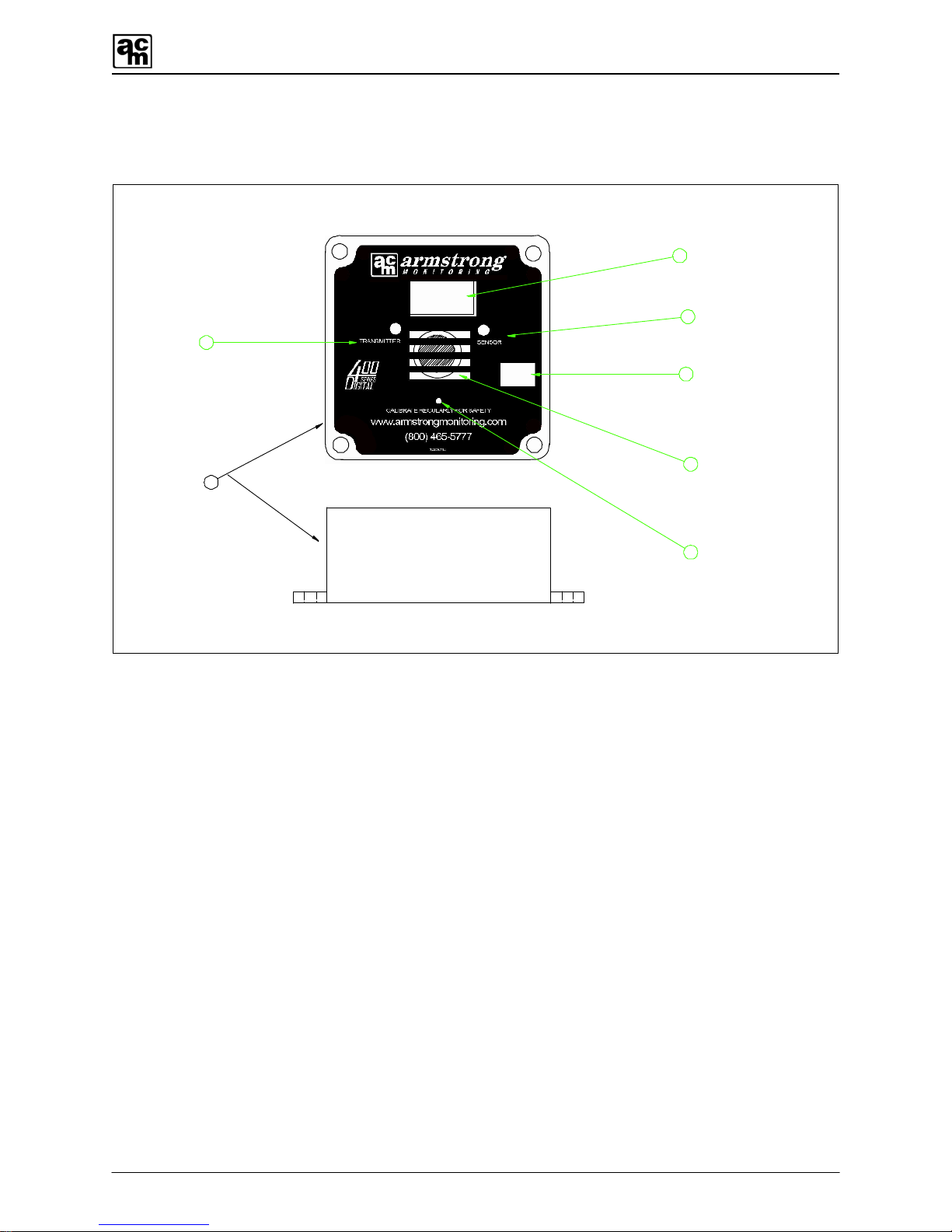
3.2 FRONT LID OVERVIEW
2
3
4
1
5
6
7
Enclosure
Display
Transmitter status
LED
Smart Sensor 2
status LED
Modbus Address
Sensor & Vent
Push button
Figure 3-1 Front Lid View
1. Enclosure: Enclosure and Lid Assembly, PVC 4”x4” Wall mount with
mount points. Enclosure Lid attaches with four screws.
2. Digital Display: Displays gas concentration & Status information, 3 Digit
User Interface for configuration
3. Transmitter Status LED: Red/Green LED
Indicates status of Transmitter.
4. Smart Sensor 2 Status LED: Red/Green LED
Indicates status of integral Smart Sensor 2.
5. MODBUS Address This is a write on area matching the MODBUS device ID
(Address). The indication here may be factory set and can
be changed as needed.
6. Sensor & Vent This vent allows target gas to flow into the sensor. The vent
is also used for gas calibration.
7. Pushbutton: Momentary On/Off Pushbutton
User Interface for Configuration.

AMC-400 Series Digital Transmitter with Smart Sensor 2
11
3.3 REAR LID OVERVIEW
GND VDD V+
8
9
10
11
RS485 A
RS485 B
CGND
SIG GND
+
Power and communication
connector
GND test point
VDD test point
V+ test point
Transmitter female connector
12
13
14
Smart Sensor 2 Termination
Modbus Termination
SS2 Board mounted
15
SS2 mounting hole
Transmitter board
SS2 board
Mounting Standoffs
Sensor
(connects to SS2 male connector)
-
Figure 3-2 Rear Lid View
Note:
When connecting the Smart Sensor 2 module, assure its male header pins are aligned
to mate the receptacle of the Digital transmitter.
Warning:
Care must be taken when connecting services to Power and Communication
Connector. Do not use SIG GND on AMC-400 for powering. Cable shield(s) are to be
connected to CGND. Mixing power and communication connections can cause
permanent damage. Consistent polarity of RS-485 wire is required throughout network
for proper system operation.

AMC-400 Series Digital Transmitter with Smart Sensor 2
12
8. Power and Communication
Connector: This 6 pin male plug connector contains both power and
communication network connection points. The power is
normally 24VDC and the communication network is
MODBUS over RS-485.
9. GND Test Point: This GND Test Point is to be used by service technicians
only with appropriate instrumentation such as a voltmeter. It
is the signal reference point for the digital transmitter control
logic.
10. VDD Test Point: This VDD Test Point is to be used by service technicians
only. It is the digital transmitter control logic supply voltage
and must be 5+/-5% Volts DC.
11. V+ Test Point: This V+ Test Point is to be used by service technicians only.
It is the digital transmitter rectified unregulated power input
and meet the range specified in 2.1.1 AMC-400 DIGITAL
TRANSMITTER SPECIFICATION.
12. SS2 Female Connector: This 7 pin connector mates with the Smart Sensor 2 Module
male connector. This connector carries the power and
communication for Smart Sensor 2.
13. Smart Sensor 2 Termination: Default position: AC Termination (Pins 1-2, bottom). This
termination allows AC or DC Termination for the Smart
Sensor 2 RS-485 signaling.
14. MODBUS Termination: Default position: No Termination (Pin 2) as shown in Figure
3-2. This termination allows AC or DC Termination for the
MODBUS RS-485 signaling. Use AC Termination (Pin 1-2,
bottom) when transmitter is an end point on bus.
15. SS2 Mounting Hole: This mounting hole contains two standoffs to support the
Smart Sensor 2 Module. One standoff is a stud the other is
nylon press-fit.

AMC-400 Series Digital Transmitter with Smart Sensor 2
13
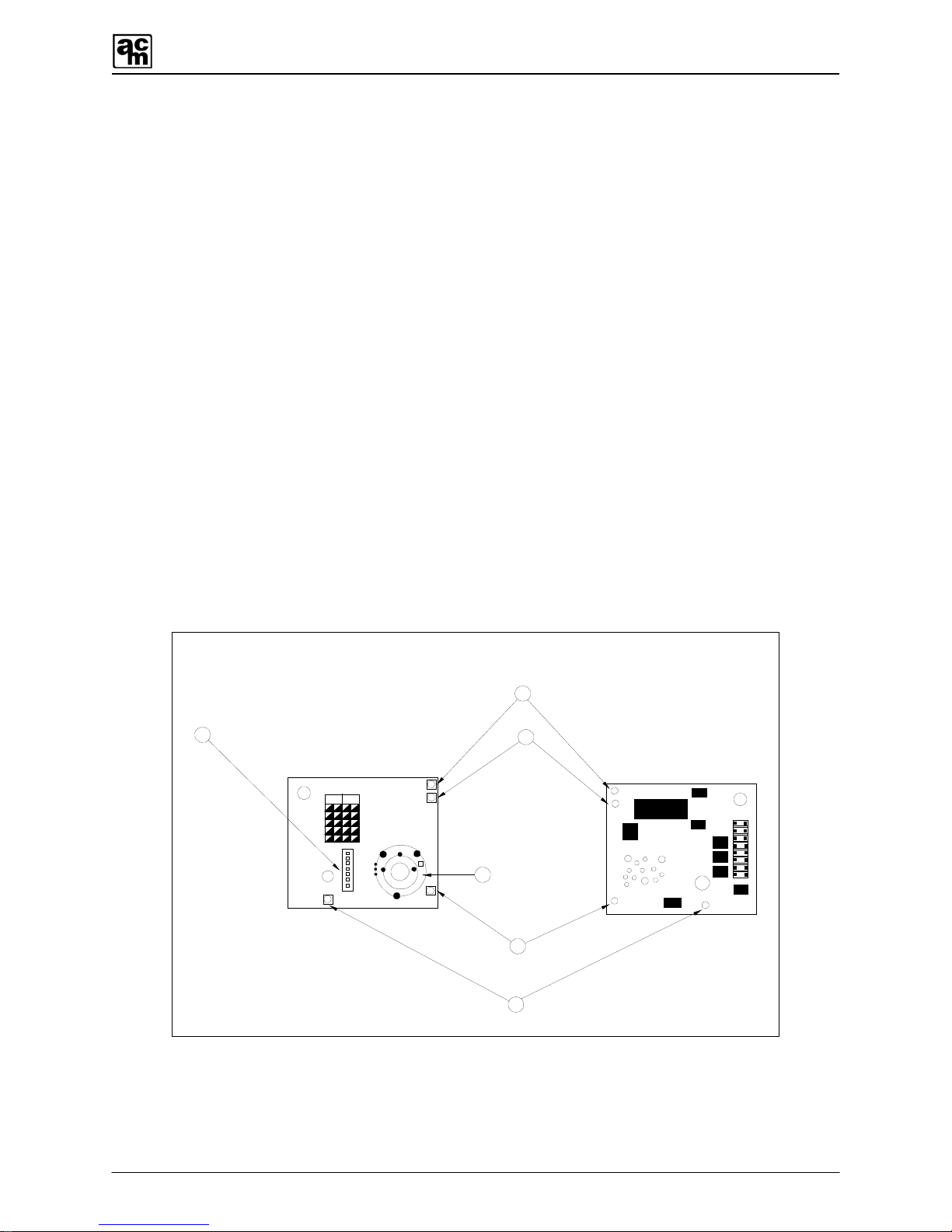
3.4 SMART SENSOR 2 MODULE WITH ELECTROCHEMICAL SENSOR
OVERVIEW
12345
67 89 0
REV
12 3 45
67890
VER
SNS1
SNS4
SNS2
SNS3
Smart Sensor 2 Board
16
SS2 male connector
Sensor Location
GND test point
VDD test point
VREF test point
CTR
SIG
Front Back
19
22
20
21
18
17
VDD
GND
SIG
VREF CTR
Figure 3-3 Smart Sensor 2 Module with Electrochemical Sensor View
16. SS2 Male Connector: This 7 pin connector mates with the Digital Transmitter
female connector. This connector carries the power and
communication.
17. VDD Test Point: This VDD Test Point is to be used by service technicians
only. It is the Smart Sensor 2 control logic supply voltage
and must be 5+/-5% Volts DC.
18. GND Test Point: This GND Test Point is to be used by service technicians
only with appropriate instrumentation such as a voltmeter. It
is the signal reference point for the Smart Sensor 2 control
logic.
AMC-400 Series Digital Transmitter with Smart Sensor 2
14
19. VREF Test Point: This VREF Test Point is to be used by service technicians
only. It is the potentiostat sensor reference and must be 1.8
Volts DC.
20. Sensor: This component may be a variety of 2 or 3 pin
electrochemical sensors. This component is permanently
fastened to the Smart Sensor 2 Module.
21. CTR Test Point: This CTR Test Point is to be used by service technicians
only with appropriate instrumentation such as a voltmeter. It
is the potentiostat counter output used by a 3 pin
electrochemical sensor. Under ideal operation zero gas
situation it is normally 1.8 Volts DC VREF.
22. SIG Test Point: This Sig Test Point is to be used by service technicians only
with appropriate instrumentation such as a voltmeter. It is
the potentiostat sensor output used. Under normal
operation zero gas situation it tracks the 1.8 Volts DC
VREF. When CO gas is applied this SIG Test Point
increases toward 3.6 Volts DC. When NO2 gas is applied
this SIG Test Point decreases towards 0 Volts DC.
3.5 SMART SENSOR 2 MODULE WITH CATALYTIC SENSOR
OVERVIEW
GND
VDD
VREF
SNS2
SNS3SNS1
Smart Sensor 2 Module with Catalytic Sensor
16
20
SS2 male connector
Sensor Location
GND test point
VDD test point
VREF
SIG
Front Back
REV
VER
1
23
45
67
89
01
23
45
67
89
0
SIG
SNS4
SNS5
SNS6 SNS7
TP3
TP1
TP2
TP4
19
test point
18
17
21
Figure 3-4 Smart Sensor 2 Module with Catalytic Sensor View

AMC-400 Series Digital Transmitter with Smart Sensor 2
15
16.SS2 Male Connector: This 7 pin connector mates with the Digital Transmitter
female connector. This connector carries the power and
communication.
17.VDD Test Point: This VDD Test Point is to be used by service technicians
only. It is the Smart Sensor 2 control logic supply voltage
and must be 3.45+/-5% Volts DC.
18.GND Test Point: This GND Test Point is to be used by service technicians
only with appropriate instrumentation such as a voltmeter. It
is the signal reference point for the Smart Sensor 2 control
logic.
19.VREF Test Point: This VREF Test Point is to be used by service technicians
only. It must be 1.8 Volts DC.
20.Sensor: This component is a 3 pin Catalytic sensor. This component
is permanently fastened to the Smart Sensor 2 Module.
21.SIG Test Point: This Sig Test Point is to be used by service technicians only
with appropriate instrumentation such as a voltmeter. It is
the amplified sensor output as seen by the analog to digital
converter. Under normal operation zero gas situation it
tracks the 1.8 +/- 0.4 Volts DC VREF. When a combustible
gas is applied this SIG Test Point increases toward 3.45
Volts DC.
3.6 CATALYTIC SENSOR CHARACTERISTICS
3.6.1 CONTAMINANTS
The performance of the catalytic combustion type gas sensors may be affected by exposure to
substances known as poisons and inhibitors. Inhibitors are present in volatile substances
containing halogens or sulphur compounds. Sensors may recover their sensitivity
characteristics after exposure to inhibitors has ceased. Some substances produce a permanent
poisoning effect on the catalyst. These poisons include silicone oils, greases and petroleum
additives such as tetraethyl lead and phosphate esters. Always be cautious of by products that
may evolve from the thermal decomposition of materials such as plastics.
3.6.2 CROSS SENSITIVITY
The catalytic sensor is also sensitive to other combustible gases. See Table 3-1. As a result the
sensor will provide protection for some of these gases as well.

AMC-400 Series Digital Transmitter with Smart Sensor 2
16
Gas Relative Sensitivity LEL (%vol)
Methane 100 5
Hydrogen 97 4
Ethylene 83 3
Propane 80 2
Butane 83 1.5
n-Pentane 71 1.5
Hexanes 63 1.2
Table 3-1 Cross Sensitivity
3.6.3 MAXIMUM RANGE
Although the sensor output is linear to 100%LEL, the use of catalytic sensors is not
recommended over that range. Above the LEL value there may be insufficient oxygen to
catalyze all of the combustible gas: the output may decrease and indicate a concentration of
less than 100% LEL, causing an ambiguity in the instrument reading.
3.6.4 ALARM RECOMMENDATIONS
The 400 Digital Transmitter equipped with a combustible catalytic sensor is designed for non
hazardous location with the primary purpose of initiating ventilation when low concentration of
combustible gases are detected (20-40%LEL). However, due to the dangers associated with
combustible gases we recommend setting an ‘ultra high’ latching alarm at level approaching the
LEL ie. 80% LEL.
Table of contents


