Westlock Controls Corporation D510 User manual

Quick start installation and operating instructions for models D510 with non-intrusive calibration
and D520 without non-intrusive calibration
www.westlockcontrols.com
Copyright © Crane Co. All rights reserved
Warnings
• Models D510 and D520 contain
aluminum and is at potential risk of
ignition by impact or friction. Care must be
taken into account during installation and use to
prevent impact or friction.
• Never remove enclosure cover or make/break
electrical connections with power connected to
the unit.
• Perform all wiring in accordance with site and
local codes and the National Electric Code
ANSI-NFPA-70 (US) or the Canadian Electric
Code Part I (Canada) for the appropriate area
classifications.
• Confirm that the DEPIC2 model being installed
is approved for the hazardous area (consult unit
identification label).
• Confirm that power supplied to switches and
solenoid is within rated specifications listed on
the unit identification label.
• Protect the unit from exposure to aggressive
substances or atmospheres to ensure that
hazard rating is not compromised.
DEPIC 2 HART POSITION TRANSMITTER - MODELS D510 AND D520
INSTALLATION AND OPERATIONS MANUAL
Page 1 of 14VCIOM-04592-EN 17/03
1 INTRODUCTION
1.1 Product Certification
FM15ATEX0061X
II 2 G Ex db IIB+H2 T5 Gb
Ta= -50°C to +85°C
II 2 D Ex tb IIIC T88°C Db
Ta=-50°C to + +85°C
IP66/67
IEC Ex
IECEx FMG 15.0036X
Ex db IIB+H2 T5 Gb Ta= -50°C to 85°C
Ex tb IIIC T88°C Db
Ta=-50°C to + 85°C
IP66/67
CLASS I DIVISION1, Groups B, C, and D.
CLASS II/III, DIVISION 1, Groups E,F, and G
TYPE 4, 4x IP66/67
Ta= -50°C to 85°C
CLASS1, ZONE 1, AEx db IIB+H2 Gb
ZONE 21, AEx/Ex tb IIIC T88°C Db
Ta= -50°C to 85°C
• Disconnect power to solenoids and the inlet
air supply before conducting any valve service
or maintenance. Avoid the introduction of any
contaminants into the valve.
• Before using these products with fluids/
compressed gases other than air or for non-
industrial applications, consult the factory.
This product is not intended for use in life
support systems.
• Installation in poorly ventilated confined areas,
with any potential of gases other than oxygen
being present, can lead to a risk of personnel
asphyxiation.

Page 2 of 14
Copyright © Crane Co. All rights reserved
2 INITIAL SETUP
2.1 Mounting transmitter on a rotary actuator
Step 1 Mount bracket and inner beacon
coupler to actuator. If actuator shaft
has a tapped hole, fasten using
proper flat head screw. If actuator
does not have a tapped hole, fasten
using set screws on side of coupler.
(See Figure 2-1)
Step 2 Press fit the inner beacon to the
inner beacon coupler. The inner
beacon needs to be properly
oriented. Use the symbols on the
top of the inner beacon to mount as
shown in Condi¬tion 1 or Condition 2.
(see Figure 2-2).
Condition 1 and Condition 2 show the
placement of the inner beacon with
respect to the Transmitter housing
while the actuator is in the fail
position.
Step 3 Mount the Transmitter to the
bracket. As stated in Step 2 make
sure that the Transmitter is mounted
in a fashion that properly orients it
with respect to the inner beacon.
DEPIC 2 HART POSITION TRANSMITTER - MODELS D510 AND D520
INSTALLATION AND OPERATIONS MANUAL
Figure 2-1
BRACKET / COUPLER MOUNTING
Placed at 9:00
Actuator accessory
mounting shaft
Set screw
Inner beacon coupler
Flat head screw
Condition 2: Actuator fails in a counter clockwise direction.
Placed at 3:00
Bracket
Condition 1: Actuator fails in a clockwise direction.
Placed at 6:00
Placed at 6:00
VCIOM-04592
Figure 2-2
DIRECT MOUNT BEACON ORIENTATION

2
31
Page 3 of 14
DEPIC 2 HART POSITION TRANSMITTER - MODELS D510 AND D520
INSTALLATION AND OPERATIONS MANUAL
VCIOM-04592
2.2 Remote mount
Step 1 Mount bracket and inner beacon
coupler to actuator as described in
Section 2.1 Step 1.
Step 2 Press fit the inner beacon to the
inner beacon coupler. The inner
beacon needs to be properly
oriented. Use the symbols on the
top of the inner beacon to mount as
shown in Condition 1 or
Condition 2. (See Figure 2-3).
Condition 1 and Condition 2 show
the placement of the inner beacon
with respect to the position sensor
housing while the actuator is in the
fail position.
Step 3 Mount the position sensor to the
bracket. As stated in Step 2 make
sure that the position sensor is
mounted in a fashion that properly
orients it with respect to the inner
beacon.
Placed at 9:00
Condition 2: Actuator fails in a counter clockwise direction.
Placed at 3:00
Condition 1: Actuator fails in a clockwise direction.
Placed at 6:00
Placed at 6:00
Figure 2-3
REMOTE MOUNT BEACON ORIENTATION
Conduit
entry
Position
sensor
Inner
Beacon
Actuator
(in fail position)
Conduit
entry
Position
sensor
Inner
Beacon
Actuator
(in fail position)
3 PNEUMATIC CONNECTIONS
3.1 DEPIC Transmitters with the Pressure
Profiling feature enabled requires
pneumatic pressure for both the supply
pressure and output pressure.
NOTE
The pneumatic diagram shows a typical 3/2 solenoid
valve.
Option available of a factory fitted 3/2 solenoid valve in
the DEPIC 520 Only.
3.2 The air supply to the DEPIC2 must be
clean, dry, oil free instrument air per
ANSI/ISA-7.0.01-1996 and ISO 8573-1:2010
or later.
P1 port
Pneumatic supply
3 way valve
Single acting cylinder
P2 port
MAXIMUM PARTICLE SIZE AND CONCENTRATION OF SOLID CONTAMINANTS
Class Maximum particle size (microns) Maximum concentration (mg/m3)
3 5 5
MAXIMUM OIL CONTENT
Class Maximum concentration (mg/m3)
3 1
Maximum supply pressure is 120 psi.
All pneumatic connections are ¼” NPT or BSP.
Copyright © Crane Co. All rights reserved

3
1
4
ANALOG
INPUT
5
6
4-20mA(+)
4-20mA(-)
(+)
2
SOLENOID
OUTPUT
SOLENOID
INPUT
(-)
(+)
(-)
EXTERNAL
SOLENOID
Page 4 of 14
DEPIC 2 HART POSITION TRANSMITTER - MODELS D510 AND D520
INSTALLATION AND OPERATIONS MANUAL
Warning
See the warnings section of this document for important warnings pertaining to the wiring of
the DEPIC Transmitters. Ensure care is taken with removing that fitting the Exd cover before
and after wiring.
VCIOM-04592
4 FIELD WIRING
4.1 The DEPIC2 has been certified for use
in hazardous locations to international
standards. Although wiring practices may
vary from region to region it is up to the end
user to ensure that the electrical codes for
installation have been satisfied.
4.2 All unused cable entries must be plugged
with suitably certified plugs that can
maintain an ingress protection level of IP66.
4.3 For ambient temperatures below -10°C
and above +60°C, use field wiring suitable
for both minimum and maximum ambient
temperatures.
4.4 Electromagnetic compatibility (emissions
and susceptibility) is guaranteed only if,
the unit and all cables are shielded and
grounded as illustrated in Appendix A.
If the DEPIC2 is optioned with a Remote Mount,
reference to full technical manual document,
VCIOM-05044.
1. Remove cover from enclosure.
2.
Locate terminal strip (for Exd option terminal
strip is removable, See illustration on right).
3. Connect the 4 to 20 mA loop signal
to terminal points marked 1 and 2.
The 4-20 mA analog output is of the current
sink type. Typically the 24 VDC supply
required comes from the HOST system
(24VDC nominal). See figure 4-1 for a wiring
schematic.
4. Connect the solenoid coil to terminal points
3 and 4.
See figure 4-1 for wiring. Solenoid coil is 24V
with current not to exceed 500 mA. Power
to activate the solenoid comes from a Safety
Instrumented System logic solver 24V output
and is connected to terminals 5 and 6.
See figure 4-1 for wiring schematic. The SIS
logic solver output must be able to provide
sufficient current to operate the solenoid.
5. Connect electrical ground wire to green
screw on housing (ground). Do not connect
cable shield to ground. Cable shield at this
end should be isolated using a shrink tubing
or isolation tape.
6. External grounding is required for all zone
installations. All wiring must be done in
accordance with local and national electric
code. See figure 4-1 for external ground
connection.
7. After all connections have been made
(for Exd option reconnect the terminal strip)
replace cover.
CAUTION
Do not over tighten Terminal Screws. Max Torque
3.5 in-lbs. /0.4 N-m.
All unused cable entries must be plugged
with suitably certified plugs that can
maintain an ingress protection level of IP66.
Figure 4-1
CUSTOMER WIRING.
Test point for hart
communiicator
Test point for hart
communicator
4-20mA position
measured output
External ground
connection
Solenoid
output
Exd Enclosure
External
solenoid
Solenoid input
Copyright © Crane Co. All rights reserved

4.5 Electrical connections for remote mount
4.5.1 Remove cover from junction enclosure by
screwing ‘clockwise’ the cover retaining
screw using a 9/64 A/F Allen Key.
4.5.2 Locate terminal board mounting
screws (See Figure 4-2), remove the
two screws and lift up terminal board.
(See Figure 4-3).
4.5.3 Locate J3 and J4 connectors on the
bottom of terminal board and connect the
two part remote cable plugs as shown.
See Figure 4-4.
4.5.4 Replace the terminal strip board, replace
the screws and replace the cover.
NOTE
To maintain the approval compliance, ensure that
the junction enclosure cover locking screw is used.
Screw the cover down to create a water tight seal,
then rotate the locking screw anti-clockwise until the
head of the screw mates with the underside of the
cover. See Appendix B.
4.5.5 If necessary, cut the remote cable to
required length.
NOTE
When shortening the cable, ensure to cut the end
opposite female connector.
4.5.6 Locate remote transmitter enclosure and
remove cover.
4.5.7 Wire the cable from junction enclosure to
remote transmitter. See Figure 4-5.
4.5.8 After all connections have been made
replace remote transmitter cover.
Figure 4-3
JUNCTION ENCLOSURE ISO VIEW
Plug two (3 pin)
connectors
Terminal board
Yellow
Green
Figure 4-2
JUNCTION ENCLOSURE TOP VIEW (NO COVER)
Terminal board mounting screw Junction cover
Terminal board
DEPIC 2 HART POSITION TRANSMITTER - MODELS D510 AND D520
INSTALLATION AND OPERATIONS MANUAL
Page 5 of 14VCIOM-04592
Terminal board mounting screw
Figure 4-4
TERMINAL BOARD BOTTOM VIEW.
Connector orientation mark
Red
Black
White
Figure 4-5
REMOTE MOUNT ENCLOSURE
Position sensor Two (3) pin connectors
(to junction enclosure of positioner)
Shield
Black
Green
Red
White
Hall effect
sensor
Wiring schematic
Copyright © Crane Co. All rights reserved

Page 6 of 14VCIOM-04592
5 QUICK SETUP
5.1 The DEPIC-2 can be configured for the
basic operation and calibrated through the
local user interface of LCD and Keypad.
When the DEPIC-2 is shipped from the
factory, it has all factory defaults settings.
However the user has to configure a few
basic settings and calibrate the device
depending on the user configuration of the
DEPIC-2. The Quick Setup provides an easy
and intuitive way to configure the basic
settings, calibrate and get the DEPIC-2 up
and running within few minutes.
5.2 When the user presses the key to
enter the menu the first time after receiving
from the factory, the DEPIC-2 will ask the
user if he wants to run the Quick Setup as
shown below. The user can select “Yes” or
“No” to run or exit the Quick Setup. If the
user selects to run the Quick Setup, the
DEPIC-2 will guide the user step by step
to enter all required settings and calibrate
the device. The DEPIC-2 must be mounted
on an actuator with proper electrical and
pneumatic connections before running the
Quick Setup. The following section explains
each step in the Quick Setup.
5.3 Using the up/down arrow keys, toggle until
‘YES’ is displayed. Then press the key
to run the Quick Setup when the DEPIC-2
shows following screen on the LCD.
DEPIC 2 HART POSITION TRANSMITTER - MODELS D510 AND D520
INSTALLATION AND OPERATIONS MANUAL
Quick Setup1/13
---------------- -
5.4 The LCD will display the following screen
to configure the DEPIC-2 for the Rotary or
Linear application.
Use the up/down arrow key to change the
selection between “Rotary” and “Linear”.
Press the Select key to accept the current
selection.
Rotary: For rotary actuators, it should be
selected as rotary as the DEPIC2 will
convert the linear position reading to
angular rotary position.
Linear:
For linear actuators, it should be selected
as linear as the DEPIC2 will compensate
non-linearity for linear magnets
Rotary/Lin 2/13
----------------
5.5 The LCD will display following screen to
configure the DEPIC-2 for the fail mode.
Use the up/down arrow key to change the
selection between “Fail Closed” and “Fail
Open”. Press the Select key to accept the
current selection.
Fail Mode 5/13
----------------
Fail Closed:
select this setting if the valve moves
towards fully closed position when
the solenoid is de-energized.
Fail Open: select this setting if the valve
moves towards fully open position
when the solenoid is de-energized.
5.6 The LCD will display following screen to
configure the DEPIC-2 for the device control
mode. Use the up/down arrow key to
change the selection between “Enable” and
“Disable”. Press the Select key to accept
the current selection.
Enable: if device control is enabled, the DEPIC
will move the valve automatically
to perform certain actions like auto
calibration and auto full stroke
signatures.
Disable: if device control is disabled, the
DEPIC will not move the valve
automatically to perform certain
actions like auto calibration and auto
full stroke signature. In this case the
user can use the manual calibration
and dynamic baseline features
to configure the device, however
the valve is required to be moved
manually to the correct position
during manual calibration.
Dev Control 6/13
------------------
Copyright © Crane Co. All rights reserved

Page 7 of 14VCIOM-04592
5.7 The LCD will display the following screen
to configure the DPEIC-2 for the ESD
monitoring. Use the up/down arrow key to
change the selection between “Enable” and
“Disable”. Press the Select key to accept
the current selection.
Enable: Emergency Shut Down monitoring is
enabled. The DEPIC-2 will generate
an alarm when the solenoid is de-
energized. The ESD alarm should
be enabled separately in the basic
configuration for the DEPIC-2 to
generate an alarm.
Disable: Emergency Shut Down monitoring
is disabled. The DEPIC-2 will not
generate an alarm when the solenoid
is de-energized.
NOTES
The factory option “ESD” must be enabled to have this
setting available for the user.
The user must have purchased a DEPIC-2 model that
has the ESD monitoring feature.
DEPIC 2 HART POSITION TRANSMITTER - MODELS D510 AND D520
INSTALLATION AND OPERATIONS MANUAL
ESD 7/13
------------
5.8 The LCD will display the following
screen to configure the DEPIC-2 for
the pressure sensor-1 operation.
Use the up/down arrow key to change the
selection between “Enable” and “Disable”.
Press the Select key to accept the current
selection.
Enable: Pressure sensor-1 is enabled. The
DEPIC-2 will assume the current
model is equipped with the pressure
sensor-1 and is pneumatically
connected to the actuator chamber.
It will show all pressure-1 related
hysteresis and alarm settings in the
full menu later on. The user must have
purchased a DEPIC-2 model that has
the pressure sensor-1.
Disable: Pressure sensor-1 is disabled. The
DEPIC-2 will assume the current
model is NOT equipped with the
pressure sensor-1 or it is not
pneumatically connected to the
actuator chamber. It will hide all
pressure-1 related hysteresis and
alarm settings in the full menu later
on.
Pressure-1 8/13
----------------
5.9 The following setting is dependent on the
pressure sensor-1 configuration. If the
user has disabled the pressure sensor-1
in the previous step, the DEPIC-2 will skip
this step otherwise the LCD will display the
following screen to configure the DEPIC-2
for the pressure sensor-2 operation. Use
the up/down arrow key to change the
selection between “Enable” and “Disable”.
Press the Select key to accept the current
selection.
Enable: pressure sensor-2 is enabled. The
DEPIC-2 will assume the current
model is equipped with the pressure
sensor-2 and is pneumatically
connected. It will show all pressure-2
related hysteresis and alarm settings
in the full menu later on. The user
must have purchased a DEPIC-2
model that has the pressure sensor-2.
Disable:
pressure sensor-2 is disabled. The
DEPIC-2 will assume the current model
is NOT equipped with the pressure
sensor-2 or it is not pneumatically
connected. It will hide all pressure-2
related hysteresis and alarm settings in
the full menu later on.
Pressure-2 9/13
----------------
Copyright © Crane Co. All rights reserved

Page 8 of 14VCIOM-04592
DEPIC 2 HART POSITION TRANSMITTER - MODELS D510 AND D520
INSTALLATION AND OPERATIONS MANUAL
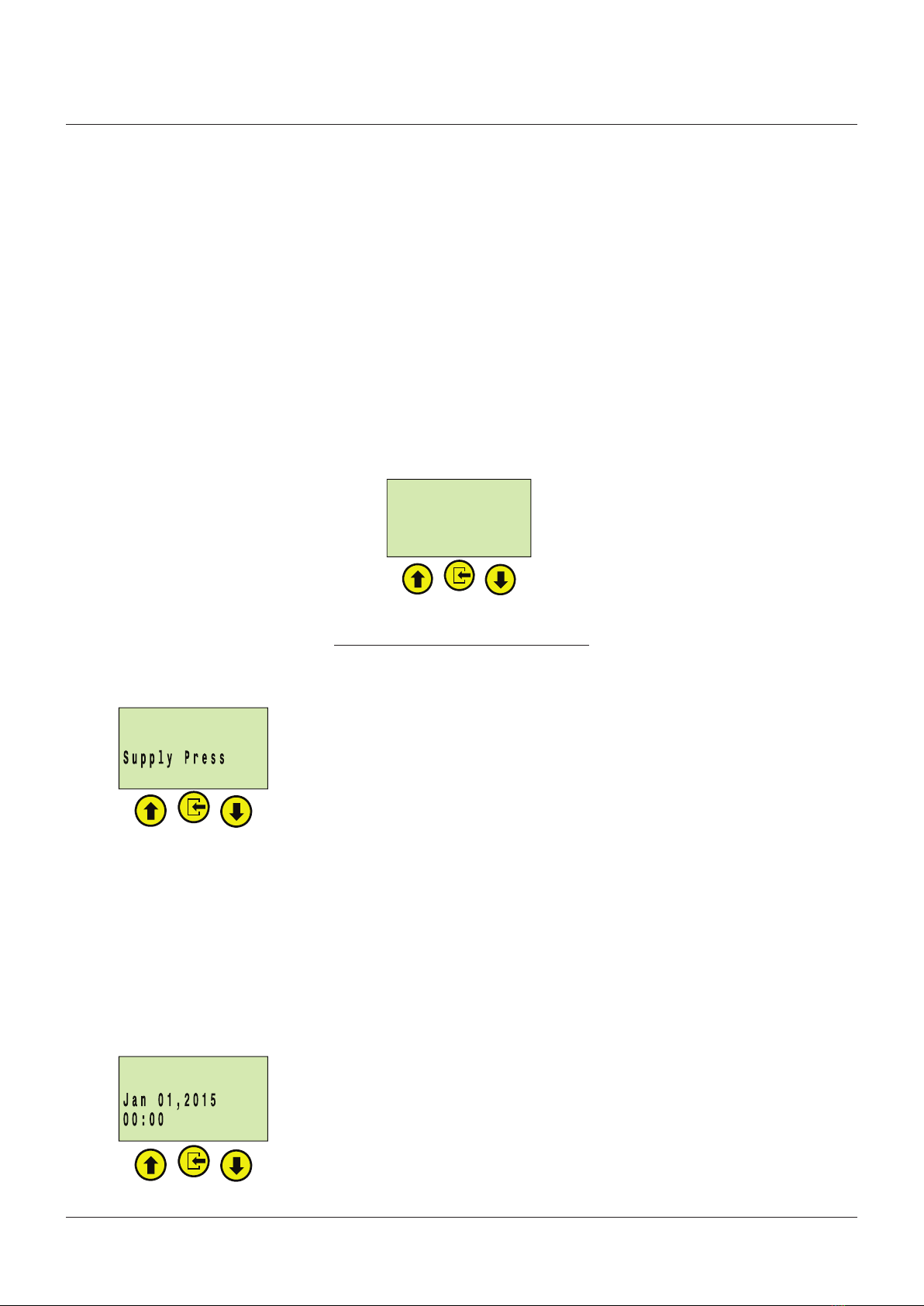
5.10 The following setting is dependent on the
pressure sensor-2 configuration. If the
user has disabled the pressure sensor-2
in the previous step, the DEPIC-2 will skip
this step otherwise the LCD will display
the following screen to configure the
DEPIC-2 for the pressure sensor-2 usage.
Use the up/down arrow key to change the
selection between “Supply Pressure” and
“Actuator Chamber Pressure”. Press the
Select key to accept the current selection.
Supply
Pressure:The DEPIC-2 will assume the
pressure sensor-2 is pneumatically
connected to monitor the supply
pressure. It will show all pressure-2
related hysteresis and alarm settings
in the full menu later on to monitor
the supply pressure. The user must
have purchased a DEPIC-2 model
that has the pressure sensor-2.
Actuator
Pressure:
The DEPIC-2 will assume the
pressure sensor-2 is pneumatically
connected to monitor the second
chamber of the actuator. It will show
all pressure-2 related hysteresis
and alarm settings in the full menu
later on to monitor the pressure in
the second actuator chamber. The
user must have purchased a DEPIC-2
model that has the pressure sensor-2.
Press-2 Use10/13
------------------
5.11
This step is dependent on the current
clock configuration. If the DEPIC-2 has the
valid time preconfigured from the factory,
it might skip this step to configure the
clock otherwise it will display the following
screen to configure the clock on the device.
Use the up/down arrow key and the select
key to configure the date and time. The
date must be configured in Month/Day/Year
format and the time must be configured in
Hours: Minutes in 24 hours format.
Clock Setup11/13
------------------
Set time in 24hr
5.12 This step is dependent on the setting
“Device Control” configured in the
previous step. If the user has disabled the
“Device Control” in the previous step, the
DEPIC-2 will display the screen to run the
manual calibration. If the user has enabled
the “Device Control” setting in the previous
step, the DEPIC- 2 will display screen to
run the auto calibration. Use the up/down
arrow key to change the selection between
“Yes” and “No”. Press the Select key to
accept the current selection.
NOTE
If ‘AUTO CALIBRATION’ has been selected, please
ensure that the correct pneumatic (see Section 3.1
and 3.2)/ electrical connections (see Figure 4.1) have
been made and are turned on and the solenoid voltage
connections have been made.
Auto Cal 12/13
------------------
This will move valve &
erase Baseline PST &
FST Data.
Continue?
No
6 USER INTERFACE
6.1 The DEPIC2 position transmitter has both
an on-board keypad/LCD menu structure
and/or a HART menu structure that can be
accessed by pressing the Select button or
from the Main Menu of a HART host. Exit
any function by pressing the up arrow
button to back out of any keypad menu or
the back arrow on the 475.
6.2 The basis of the menu systems of the
DEPIC2 were developed with a HART DD
and are emulated by the Push Button/
LCD menu system so once someone
gets used to using one interface, it
becomes easy to navigate the other
interface. See the following sections on
Configuring and Calibrating the DEPIC2.
While the menus shown below more closely
illustrate the Push Button/LCD, the HART
DD menus are very similar if not identical.
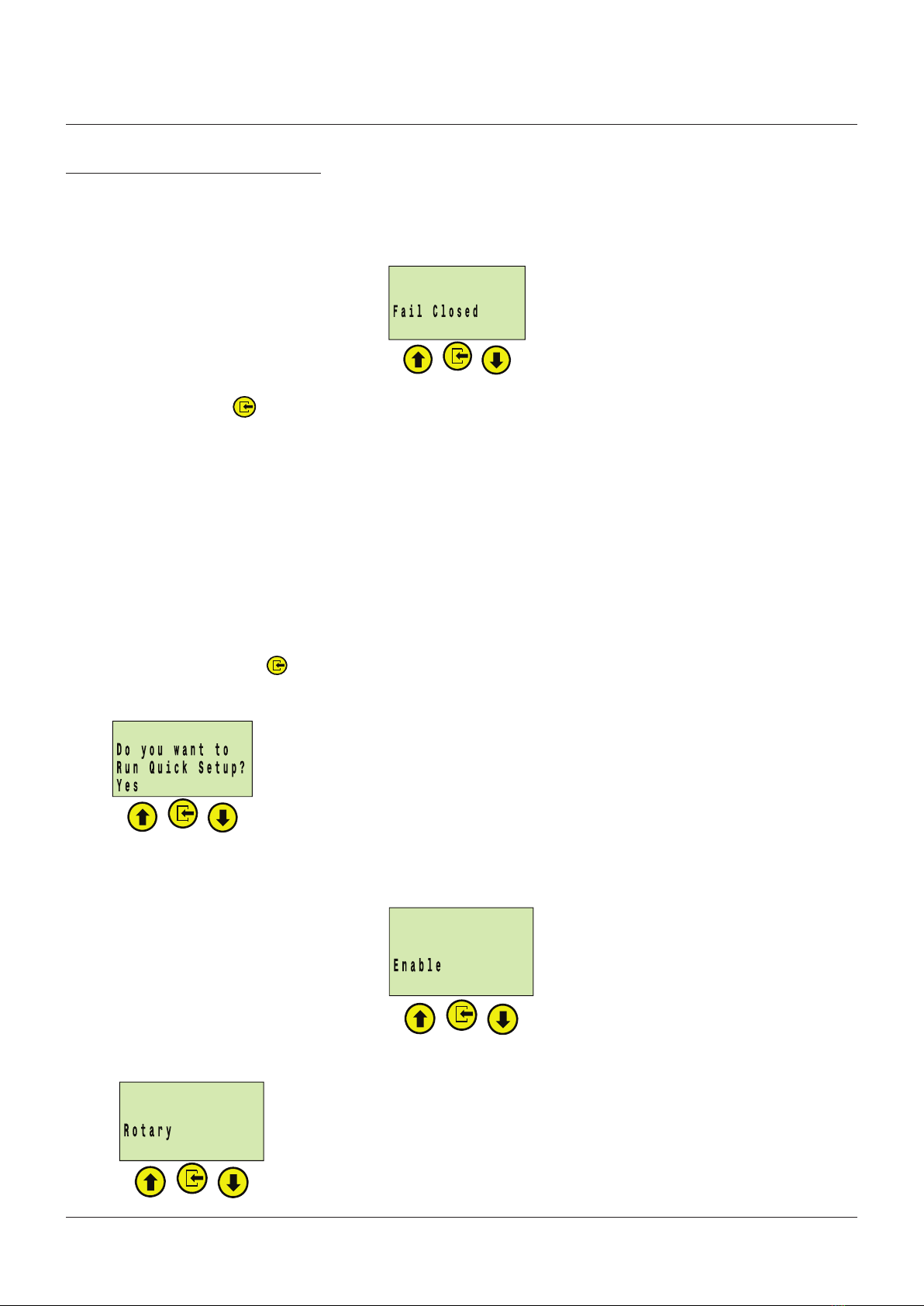
6.3 From the keypad/LCD interface, if the
device is not configured when first powered
up, it will ask the user to run the setup
wizard when the user tries to access the
menu screen. If the user selects to run
the setup wizard, it will ask the user to
configure some basic settings step by step
and perform the calibration. The setup
wizard is only available using keypad/LCD
not on the HART DD.
Copyright © Crane Co. All rights reserved

Page 9 of 14VCIOM-04592
DEPIC 2 HART POSITION TRANSMITTER - MODELS D510 AND D520
INSTALLATION AND OPERATIONS MANUAL
7 CONFIGURATION
7.1 First the device must have some basic configuration set up. As a Quick Start, this will cover
some very basic configuration for basic functionality. For more complex configurations, see
the full IOM. Figure 7.1 shows the Configuration menus to perform a basic configuration.
Figure 7-1 - Configuration Menu
------------------
Rotary DEPIC-2
May 10, 2016 17:08
% Open mA ⁰F
48.5 11.6 77.5
ALT-2 ESD-ON
Main Menu
1. Login/Logout
2. Config <-
3. Calibration
4. Diagnostics
5. Device Info
6. Device Stats
Configuration Menu
HART Configuration
Loop Current Mode
Factory Options
Set Factory Defaults
Set Date/Time
Basic Configuration
Factory Options Menu (Read Only)
PST/SOVT Options (enable/disable)
ESD Options (enable/disable)
Signature Options (enable/disable)
PST Duplex Options (enable/disable)
Manufacturer (Westlock/Crane CPE)
HART Configuration Menu
Tag (6 Alphanumeric)
Long Tag (32 Alphanumeric)
Descriptor (12 Alphanumeric)
Date
Final Assembly Number
Message
Polling Address (0-63) (+/-1)
Loop Current Mode
Basic Configuration Menu (see section 7.3)
Rotary/Linear (Rotary/Linear)
Actuator Type (spring ret) (read only)
Solenoid (Simplex/Duplex)
Device Control (enable/disable)
ESD Monitor (enable/disable)
Fail Mode (Fail Open/Fail Close)
User Password Mode (enable/disable)
Change Password (6 alphanumeric)
Display Timeouts
Date/Time Menu (see section 7.2)
RTC Status (read only)
New Clock Set
Last Clock Set (read only)
Display Timeout Menu
Temperature Display (⁰F/⁰C)
Position Display (%Open/%Close)
Rotate LCD (Normal/Rotate)
LCD Contrast (27-63 +/-1)
Keypad Timeout (1-60min +/-1)
Calibration Timeout (1-60min +/-1)
Continued On Next Page
Copyright © Crane Co. All rights reserved

Configuration Menu (continued)
PST Configuration
SOVT Configuration
Signature Configuration
Alert Hysteresis
Configuration
Service/Maintenance
Alert Configuration
SOVT Configure Menu
Auto Mode (enable/disable)
Auto SOVT Day (0-365 days +/-1)
Auto SOVT Hour (0-24 hour +/-1)
Partial Stroke Configuration Menu
PST Mode (enable/disable PST)
PST Travel Limit (0-50% +/-0.1%)
PST Travel Limit Error (0-50%)
PST Fail Limits
Cycle Limits (0-65535 +/-1)
PST Discrete I/O (enable/disable)
PST Count (0-65535 +/-1)
Auto PST
Alert Hysteresis Menu
Open Time (0-50% +/-0.1)
Close Time (0-50% +/-0.1)
Open Position (0-50% +/-0.1)
Close Position (0-50% +/-0.1)
Pressure-1 (0-50% +/-0.1)
Pressure-2 (0-50% +/-0.1)
Signature Menu (see section 7.4)
Signature Mode (enable/disable)
Pressure Sensor-2 (enable/disable)
Pressure Sensor-2 Usage (Supply/
Actuator Chamber)
Dynamic Basline (0-255 Cycle +/-1)
Service/Maintenance Menu
Service Interval (0-365 +/-1)
Last Service Date
Last Service Time
Next Service Date
Next Service Time
PST Fail Limits
PST Break Pressure Hyst (0-20% +/-1)
PST Travel Time Hyst (0-20% +/-1)
PST Total Time Limit (0-600s +/-0.1s)
Auto PST Menu
Auto Mode (enable/disable)
Auto PST Day (0-365 days +/-1)
Auto PST Hour (0-24 hour +/-1)
Error Alert (enable/disable)
Alarm Alert (enable/disable)
Service Alert (enable/disable)
Cycle Alert
ESD Alert (enable/disable)
PST Alerts (enable/disable)
Cycle Alarm Menu
Cycle Count
Cycle Limit
Cycle Alarm (enable/disable)
PST Alarms Menu
Invalid Position (enable/disable)
Solenoid Fail (enable/disable)
Exceed STTL (enable/disable)
Exceed FTTL (enable/disable)
Exceed LBPL (enable/disable)
Exceed HBPL (enable/disable)
Exceed TTL (enable/disable)
DEPIC 2 HART POSITION TRANSMITTER - MODELS D510 AND D520
INSTALLATION AND OPERATIONS MANUAL
Page 10 of 14VCIOM-04592
Copyright © Crane Co. All rights reserved

DEPIC 2 HART POSITION TRANSMITTER - MODELS D510 AND D520
INSTALLATION AND OPERATIONS MANUAL
VCIOM-04592
7.2 The first configuration to be set up is the
Date/Time. So from the Configuration menu
select Set Date/time (Date/Time Set-up on
HART), then select New Clock Set (Set New
Date/Time from HART), then set the date/
time according to your location.
7.3 Next from Configuration menu select
Basic Configuration and set the following
parameters:
• Rotary/Linear - based upon type of
actuator and magnet assembly.
• Solenoid (Simplex/Duplex) - Generally
Simplex is selected unless a redundant
solenoid is used.
• Device Control - Enable if it is desired
to let the device control the valve for
Calibration and Diagnostics.
• ESD Monitor - If Factory Option is
enabled, enable if Emergency Shut-Down
(ESD) monitoring is desired.
• Fail Mode - Select Fail-Closed or Fail-
Open depending upon the type of spring-
return actuator used.
8 CALIBRATION
8.1
Next the device must be calibrated assuming no other complexity in the Configuration is desired
from the IOM. As a Quick Start, this will cover the full calibration for this basic functionality.
For more complex calibrations, see the full IOM. Figure 8-1 shows the Calibration menus to
perform a full calibration (primarily of the position sensor and the pressure sensors if used).
7.4 Next from Configuration menu select
Signature Configuration and set the
following parameters:
• Signature Mode - If Factory Option is
enabled, enable or disable depending if
Full-Stroke and Partial-Stroke Signatures
are desired.
• Pressure Sensor 2 - Enable if the second
Pressure sensor is desired
• Pressure Sensor 2 Usage - Only if Sensor
2 is enabled, Sensor 2 can be Supply
Pressure or second chamber of actuator
(usually for double-acting, future).
Next from Configuration menu select
PST Configuration and set the following
parameters:
• PST Mode - If Factory Option is enabled,
enable or disable PST as desired.
Figure 8-1 - Calibration Menu
------------------
Rotary DEPIC-2
May 10, 2016 17:08
% Open mA ⁰F
48.5 11.6 77.5
ALT-2 ESD-ON
Main Menu
1. Login/Logout
2. Config <-
3. Calibration
4. Diagnostics
5. Device Info
6. Device Stats
Calibration Menu
Last Full Calibration
Full Manual Calibration or
Full Auto Calibration (see section 8.2)
Low Calibration
High Calibration
mA Calibration
Linear Calibration
PV Ranging
mA Calibration Menu
4-20mA Calibration Only
mA Defaults
mA Reverse
Custom mA Calibration
Manufacturer (Westlock/Crane CPE)
Page 11 of 14
Copyright © Crane Co. All rights reserved

DEPIC 2 HART POSITION TRANSMITTER - MODELS D510 AND D520
INSTALLATION AND OPERATIONS MANUAL
Page 12 of 14VCIOM-04592
8.2
From the main menu (LCD or HART), select
Calibration. Then select either Full Manual
Calibration (Full User Controlled Calibration
from HART) or Full Auto Calibration (Full
Device Controlled Calibration from HART),
one or the other is visible depending upon
the Device Control configuration set earlier.
If Device Controlled Calibration is enabled,
there is no user intervention, the device will
move the valve as needed to perform the
calibration and once completed, an indication
will be provided if there was a failure. If User
Controlled Calibration is used, there will be
instructions displayed on the LCD or from
HART to guide through the steps required,
and once completed, an indication will be
provided if there was a failure.
Note
A message appears;
‘This will move valve & erase Baseline PST & FST
Data. Continue? No/Yes’ Use UP/DOWN arrow keys to
display ‘YES’ then press the
8.3 After completing the Full Calibration, the
output current will be set for 4 mA for
closed position and 20 mA for the open
position. This current may not be exact
but will be close. If desired to calibrate
the output current to the exact value or to
change the current values for open/closed
positions, the mA Calibration menu must
be used. See the full IOM for instructions on
mA Calibration.
Also see the IOM for use of HART PV
(Primary Variable) Ranging.
CALIBRATION SCREENS
NOTES
The presentage shown on screens is the percentage of
the total calibration process that has been completed
so far. Baseline Partical Stroke Test and Full stroke
Test signatures are based on calibration values so that
they must be repeated after a new callibration is done
Full auto calibration Full manual calibration
Use up and down
arrows to change
"No" to "Yes", then
press Select
Use up and down
arrows to change
"No" to "Yes",
then press Select
Close the valve
then press
Select
Open the valve
then press Select
Copyright © Crane Co. All rights reserved

1
2
2
3
DEPIC 2 HART POSITION TRANSMITTER - MODELS D510 AND D520
INSTALLATION AND OPERATIONS MANUAL
Page 13 of 14VCIOM-04592
APPENDIX A
Field Wiring and Grounding Schematic
Control room Field wiring
To hport mux
(hart interface)
Twisted shielded pair
EPIC-2 transmitter
Westlock or customer
supplied solenoid
(do not exceed 24VDC at
500mA)
Tape shield and drain wire to
prevent contact with ground
Ground connected to green
earth screw on conduit hub
SIS controllerShield should be connected to
the shield termination point
of the output module supply
ground
PLCS or DCS
Shield
4-20 mA
input
NOTES
1. Connection from DCS or PLCto transmitter is 20 gauge shielded twisted pair (belden 8762 or equivalent).
Maximum distance is 5000 feet
2. Connection from hart multiplexer to transmitter is20gauge shield twisted pair (belden 8762 or equivalent).
Maximum distance from hart multiplexer to positioner is 6000 feet
3. Shield shall be connected to ground at one point only in order to avoid ground loops and noise interference
4. The following table per IEEE STD 518-1982 indicaes the minimum distance between cable trays and
conduits containing level1 (this includes 4-20 mA signals and 120VAC or 480 VAC, in order to minimize
electrical noise interference.
5. field wiring to be in compliance with the nec and cec for ni equipment in class 1 division 2.)
Raceway 480 VAC 120 VAC
Tray 26" 6"
Tray-conduit 18" 4"
Conduit 12" 3"
Copyright © Crane Co. All rights reserved

APPENDIX B
Enclosure Cover Lock Operation
To maintain approval compliance, the cover lock is required to be used to set. The cover lock
employs an Allen Head Cap Screw to secure to the underside of the cover when turned in the CCW
direction.
Both covers (large and small) use the same cover lock design. See figure below for reference.
1. For large cover use a
5
/
32 (.155”) or 4mm A/F Allen key and for the small cover use a
9
/
64 (.141”)
Allen key. Turning in a CCW direction to engage the screw.
2. Tighten to 12 in⋅lbs. (1.35 Nm).
DEPIC 2 HART POSITION TRANSMITTER - MODELS D510 AND D520
INSTALLATION AND OPERATIONS MANUAL
Page 14 of 14VCIOM-04592
WARNING
This symbol warns the user of possible danger. Failure to observe this warning may lead
to personal injury or death and/or severe damage to equipment.
ATTENTION
This symbol identifies information about operating the equipment in a particular manner
that may damage it or result in a system failure. Failure to observe this warning can lead
to total failure of the equipment or any other connected equipment.
NOTE
This symbol draws attention to information that is essential for understanding the
operation and/or features of the equipment.
ENGINEERING DOCUMENT REFERENCE
These installation and operating instructions
are based on the latest engineering update,
and form part of the certification for the
D510/520 DEPIC-2 series. To ensure you have
the most recent version of this IOM, please
check the document library on our website
(westlockcontrols.com).
TRANSLATIONS
Where translated the copy is taken from the
original English document VCIOM-04592-EN
as checked by the relevant notified certification
body and therefore the original English
document will prevail. No rights or liability can
be derived from any translation.
PREVIOUS DOCUMENTS
VCIOM-04592 replaces all previous installation
and operating instructions for the D510/520
including TECH-491Q
Copyright © Crane Co. All rights reserved
This manual suits for next models
1
Table of contents
Other Westlock Controls Corporation Transmitter manuals